
ECE 720 T 5 Fall 2011 CyberPhysical Systems
ECE 720 T 5 Fall 2011 Cyber-Physical Systems Rodolfo Pellizzoni
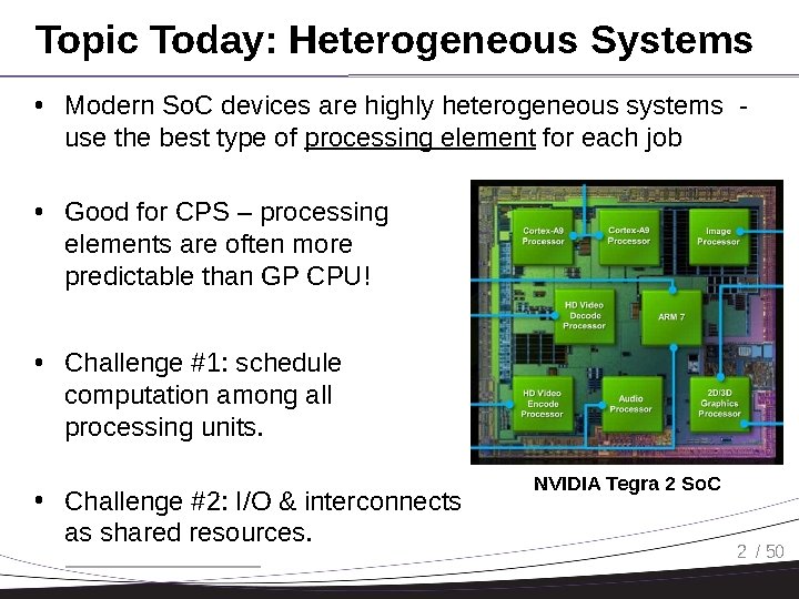
Topic Today: Heterogeneous Systems • Modern So. C devices are highly heterogeneous systems use the best type of processing element for each job • Good for CPS – processing elements are often more predictable than GP CPU! • Challenge #1: schedule computation among all processing units. • Challenge #2: I/O & interconnects as shared resources. NVIDIA Tegra 2 So. C 2 / 50
Processing Elements • Trade-offs of programmability vs performance/power consumption/area. • Not always in this order… • • • Application-Specific Instruction Processors Graphics Processing Unit Reconfigurable Field-Programmable Gate Array Coarse-Grained Reconfigurable Device I/O Processors HW Coprocessors 3 / 50
Processing Elements • Application-Specific Instruction Processors – The ISA and microarchitecture is tailored for a specific application. – Ex: Digital Signal Processor. – Sometimes “instructions” invoke HW coprocessors. • Graphics Processing Unit – Delegate graphics computation to a separate processor – First appear in the ’ 80, until the turn of the century GPUs were HW processors (fixed functions) – Now GPUs are ASIP – execute shader programs. – New trend: GPGPU – execute computation on GPU. 4 / 50
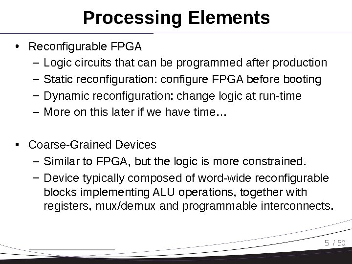
Processing Elements • Reconfigurable FPGA – Logic circuits that can be programmed after production – Static reconfiguration: configure FPGA before booting – Dynamic reconfiguration: change logic at run-time – More on this later if we have time… • Coarse-Grained Devices – Similar to FPGA, but the logic is more constrained. – Device typically composed of word-wide reconfigurable blocks implementing ALU operations, together with registers, mux/demux and programmable interconnects. 5 / 50
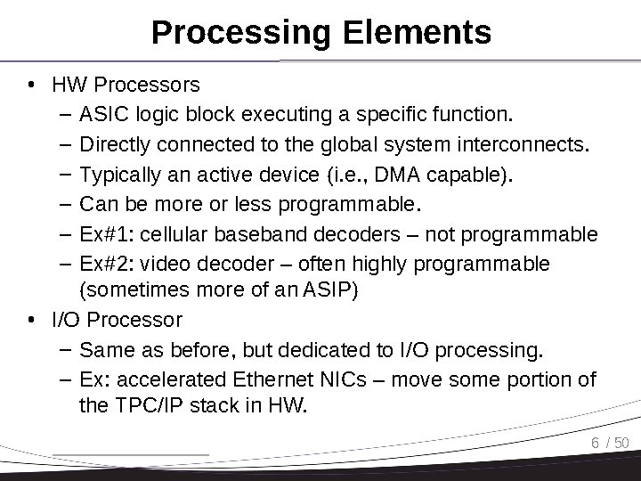
Processing Elements • HW Processors – ASIC logic block executing a specific function. – Directly connected to the global system interconnects. – Typically an active device (i. e. , DMA capable). – Can be more or less programmable. – Ex#1: cellular baseband decoders – not programmable – Ex#2: video decoder – often highly programmable (sometimes more of an ASIP) • I/O Processor – Same as before, but dedicated to I/O processing. – Ex: accelerated Ethernet NICs – move some portion of the TPC/IP stack in HW. 6 / 50
GPU for Computation • Next: computation on GPU. 7 / 50
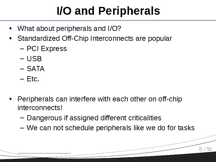
I/O and Peripherals • What about peripherals and I/O? • Standardized Off-Chip Interconnects are popular – PCI Express – USB – SATA – Etc. • Peripherals can interfere with each other on off-chip interconnects! – Dangerous if assigned different criticalities – We can not schedule peripherals like we do for tasks 8 / 50
Real-Time Control of I/O COTS Peripherals for Embedded Systems Stanley Bak, Emiliano Betti, Rodolfo Pellizzoni, Marco Caccamo, Lui Sha University of Illinois at Urbana-Champaign
COTS HW & RT Embedded Systems • Embedded systems are increasingly built by using Commercial Off-The-Shelf (COTS) components to reduce costs and time-to-market • This trend is true even for companies in the safety-critical avionic market such as Lockheed Martin Aeronautics, Boeing and Airbus • COTS components usually provide better performance: – SAFEbus used in the Boing 777 transfers data up to 60 Mbps, while a COTS interconnection such as PCI Express can reach higher transfer speeds (over three orders of magnitude) • COTS components are mainly optimized for the average case performance and not for the worst-case scenario. 2 Real-Time Control of I/O COTS Peripherals for Embedded Systems, RTSS 2009
ARINC 653 and unpredictable I/O behaviors • According to ARINC 653 avionic standard, different computational components should be put into isolated partitions (cyclic time slices of the CPU). • ARINC 653 does not provide any isolation from the effects of I/O bus traffic. A peripheral is free to interfere with cache fetches while any partition (not requiring that peripheral) is executing on the CPU. • To provide true temporal partitioning, enforceable specifications must address the complex dependencies among all interacting resources. See Aeronautical Radio Inc. ARINC 653 Specification. It defines the Avionics Application Standard Software Interface. 3 Real-Time Control of I/O COTS Peripherals for Embedded Systems, RTSS 2009
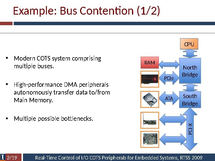
Example: Bus Contention (1/2) CPU • Modern COTS system comprising multiple buses. • High-performance DMA peripherals autonomously transfer data to/from Main Memory. RAM PCIe ATA North Bridge South Bridge PCI-X • Multiple possible bottlenecks. 2/19 Real-Time Control of I/O COTS Peripherals for Embedded Systems, RTSS 2009
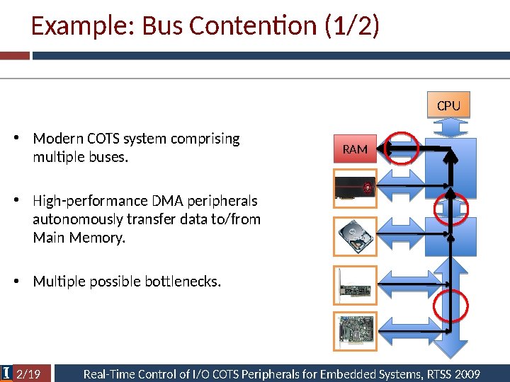
Example: Bus Contention (1/2) CPU • Modern COTS system comprising multiple buses. RAM • High-performance DMA peripherals autonomously transfer data to/from Main Memory. • Multiple possible bottlenecks. 2/19 Real-Time Control of I/O COTS Peripherals for Embedded Systems, RTSS 2009
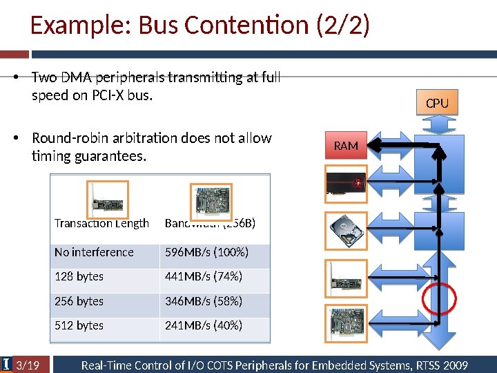
Example: Bus Contention (2/2) • Two DMA peripherals transmitting at full speed on PCI-X bus. • Round-robin arbitration does not allow timing guarantees. 3/19 Transaction Length Bandwidth (256 B) No interference 596 MB/s (100%) 128 bytes 441 MB/s (74%) 256 bytes 346 MB/s (58%) 512 bytes 241 MB/s (40%) CPU RAM Real-Time Control of I/O COTS Peripherals for Embedded Systems, RTSS 2009
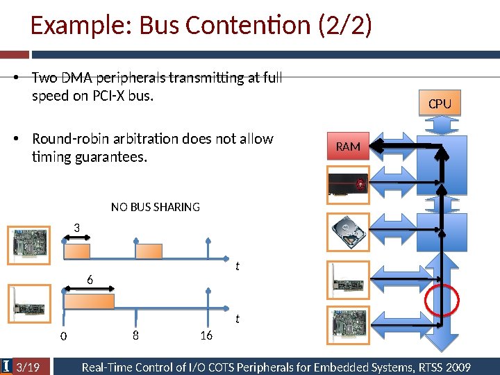
Example: Bus Contention (2/2) • Two DMA peripherals transmitting at full speed on PCI-X bus. • Round-robin arbitration does not allow timing guarantees. CPU RAM NO BUS SHARING 3 t 6 t 0 3/19 8 16 Real-Time Control of I/O COTS Peripherals for Embedded Systems, RTSS 2009
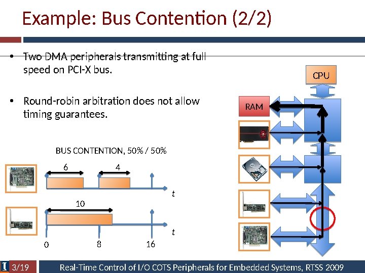
Example: Bus Contention (2/2) • Two DMA peripherals transmitting at full speed on PCI-X bus. • Round-robin arbitration does not allow timing guarantees. CPU RAM BUS CONTENTION, 50% / 50% 6 4 t 10 t 0 3/19 8 16 Real-Time Control of I/O COTS Peripherals for Embedded Systems, RTSS 2009
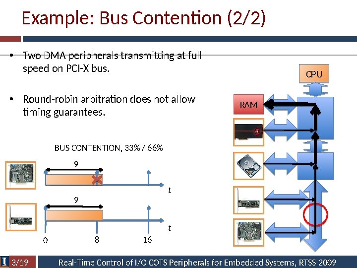
Example: Bus Contention (2/2) • Two DMA peripherals transmitting at full speed on PCI-X bus. • Round-robin arbitration does not allow timing guarantees. CPU RAM BUS CONTENTION, 33% / 66% 9 t 0 3/19 8 16 Real-Time Control of I/O COTS Peripherals for Embedded Systems, RTSS 2009
The Need for an Engineering Solution • Analysis is possible but bounds are pessimistic and require the specification of many parameters. • Average case significantly lower than worst case. – Main issue: COTS arbiters are not designed for predictability. • We propose engineering solutions to control peripheral traffic. • Main idea: we need to provide traffic isolation by scheduling peripherals on the bus, like we schedule tasks on CPU. 26 Real-Time Control of I/O COTS Peripherals for Embedded Systems, RTSS 2009
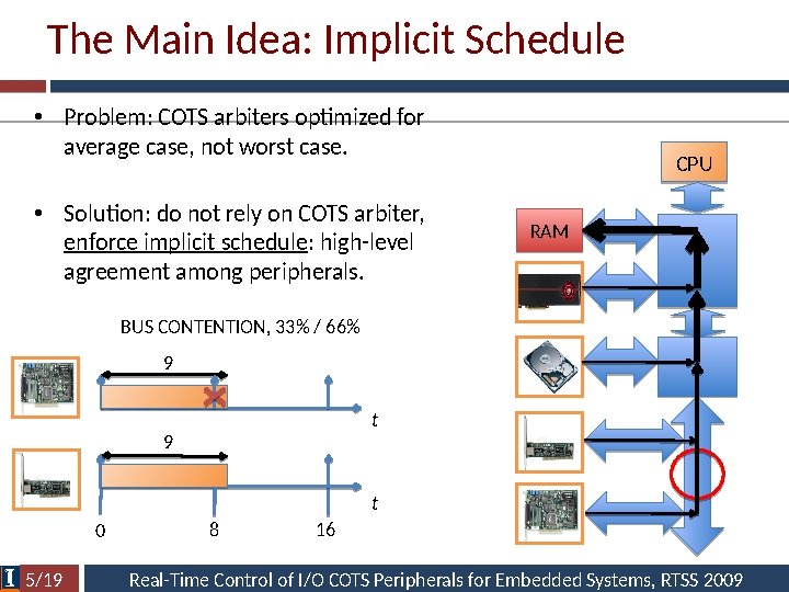
The Main Idea: Implicit Schedule • Problem: COTS arbiters optimized for average case, not worst case. • Solution: do not rely on COTS arbiter, enforce implicit schedule: high-level agreement among peripherals. CPU RAM BUS CONTENTION, 33% / 66% 9 t 0 5/19 8 16 Real-Time Control of I/O COTS Peripherals for Embedded Systems, RTSS 2009
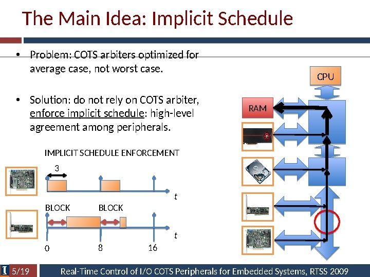
The Main Idea: Implicit Schedule • Problem: COTS arbiters optimized for average case, not worst case. • Solution: do not rely on COTS arbiter, enforce implicit schedule: high-level agreement among peripherals. CPU RAM IMPLICIT SCHEDULE ENFORCEMENT 3 t BLOCK t 0 5/19 8 16 Real-Time Control of I/O COTS Peripherals for Embedded Systems, RTSS 2009
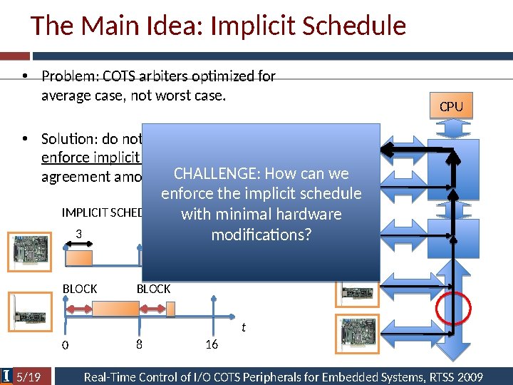
The Main Idea: Implicit Schedule • Problem: COTS arbiters optimized for average case, not worst case. CPU • Solution: do not rely on COTS arbiter, RAM enforce implicit schedule: high-level CHALLENGE: How can we agreement among peripherals. enforce the implicit schedule IMPLICIT SCHEDULE ENFORCEMENT with minimal hardware 3 modifications? t BLOCK t 0 5/19 8 16 Real-Time Control of I/O COTS Peripherals for Embedded Systems, RTSS 2009
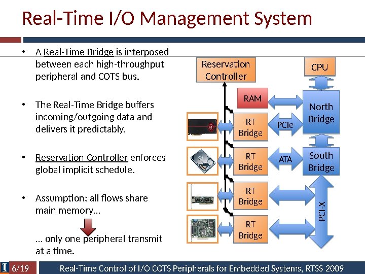
Real-Time I/O Management System Reservation Controller CPU RAM • The Real-Time Bridge buffers incoming/outgoing data and delivers it predictably. RT Bridge PCIe • Reservation Controller enforces global implicit schedule. RT Bridge ATA • Assumption: all flows share main memory… … only one peripheral transmit at a time. 6/19 RT Bridge North Bridge South Bridge PCI-X • A Real-Time Bridge is interposed between each high-throughput peripheral and COTS bus. Real-Time Control of I/O COTS Peripherals for Embedded Systems, RTSS 2009
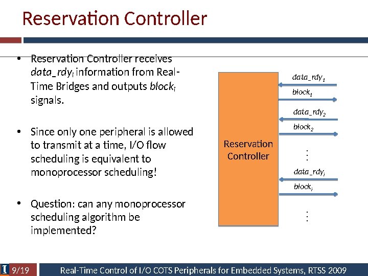
Reservation Controller • Reservation Controller receives data_rdyi information from Real. Time Bridges and outputs blocki signals. data_rdy 1 block 1 data_rdy 2 block 2 Reservation Controller . . . • Since only one peripheral is allowed to transmit at a time, I/O flow scheduling is equivalent to monoprocessor scheduling! data_rdyi • Question: can any monoprocessor scheduling algorithm be implemented? 9/19 . . . blocki Real-Time Control of I/O COTS Peripherals for Embedded Systems, RTSS 2009
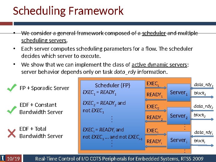
Scheduling Framework • We consider a general framework composed of a scheduler and multiple scheduling servers. • Each server computes scheduling parameters for a flow. The scheduler decides which server to execute. • We show that we can implement the class of active dynamic servers: server behavior depends only on task data_rdy information. EXEC 1 READY 1 EDF + Constant Bandwidth Server EXEC 2 = READY 2 and not EXEC 1 EXEC 2 EDF + Total Bandwidth Server EXECi = READYi and EXECi not EXEC 1 … and not EXECi-1 READYi. . . EXEC 1 = READY 1 10/19 READY 2 data_rdy 1 Server 1 block 1 data_rdy 2 Server 2 block 2 . . . Scheduler (FP) data_rdyi Serveri blocki . . . FP + Sporadic Server Real-Time Control of I/O COTS Peripherals for Embedded Systems, RTSS 2009
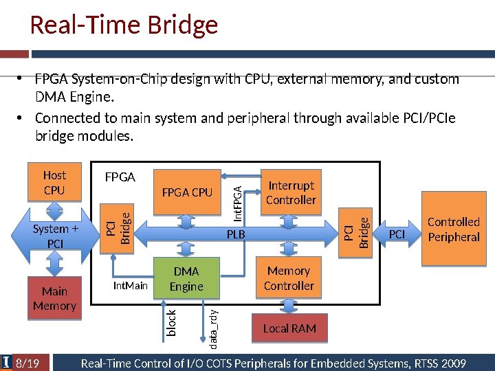
Real-Time Bridge • FPGA System-on-Chip design with CPU, external memory, and custom DMA Engine. • Connected to main system and peripheral through available PCI/PCIe bridge modules. 8/19 Int. Main PCI Bridge Int. FPGA Interrupt Controller PLB PCI Controlled Peripheral Memory Controller DMA Engine data_rdy Main Memory FPGA CPU block System + PCI FPGA PCI Bridge Host CPU Local RAM Real-Time Control of I/O COTS Peripherals for Embedded Systems, RTSS 2009
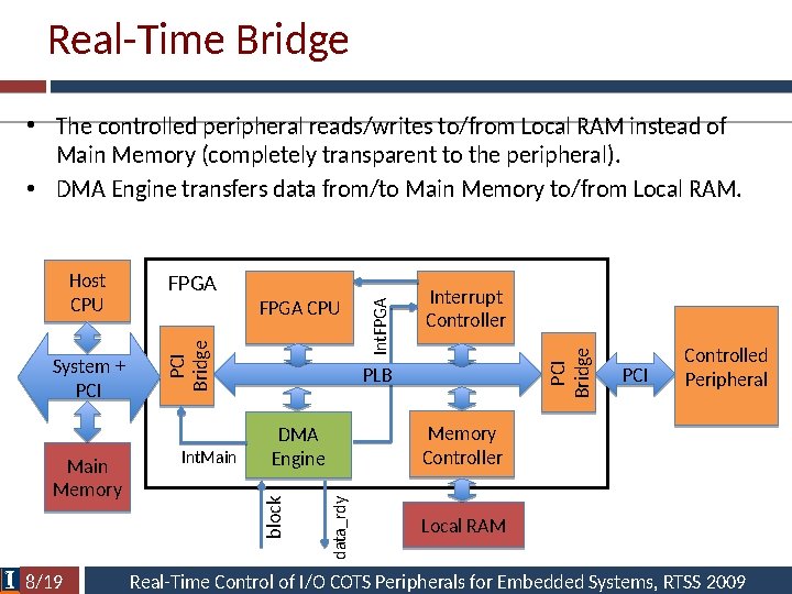
Real-Time Bridge • The controlled peripheral reads/writes to/from Local RAM instead of Main Memory (completely transparent to the peripheral). • DMA Engine transfers data from/to Main Memory to/from Local RAM. 8/19 Int. Main PCI Bridge Int. FPGA Interrupt Controller PLB PCI Controlled Peripheral Memory Controller DMA Engine data_rdy Main Memory FPGA CPU block System + PCI FPGA PCI Bridge Host CPU Local RAM Real-Time Control of I/O COTS Peripherals for Embedded Systems, RTSS 2009
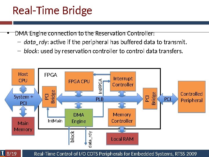
Real-Time Bridge • DMA Engine connection to the Reservation Controller: – data_rdy: active if the peripheral has buffered data to transmit. – block: used by reservation controller to control data transfers. 8/19 Int. Main PCI Bridge Int. FPGA Interrupt Controller PLB PCI Controlled Peripheral Memory Controller DMA Engine data_rdy Main Memory FPGA CPU block System + PCI FPGA PCI Bridge Host CPU Local RAM Real-Time Control of I/O COTS Peripherals for Embedded Systems, RTSS 2009
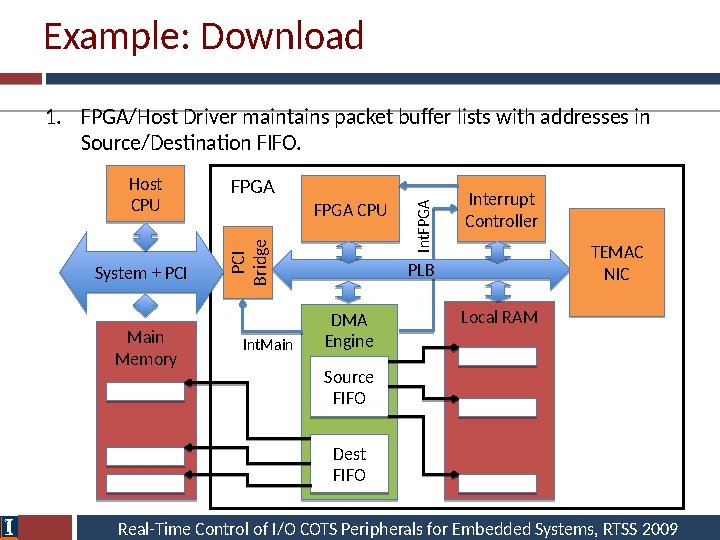
Example: Download 1. FPGA/Host Driver maintains packet buffer lists with addresses in Source/Destination FIFO. System + PCI Main Memory FPGA CPU Int. Main Int. FPGA PCI Bridge Host CPU Interrupt Controller TEMAC NIC PLB DMA Engine Local RAM Source FIFO Dest FIFO Real-Time Control of I/O COTS Peripherals for Embedded Systems, RTSS 2009
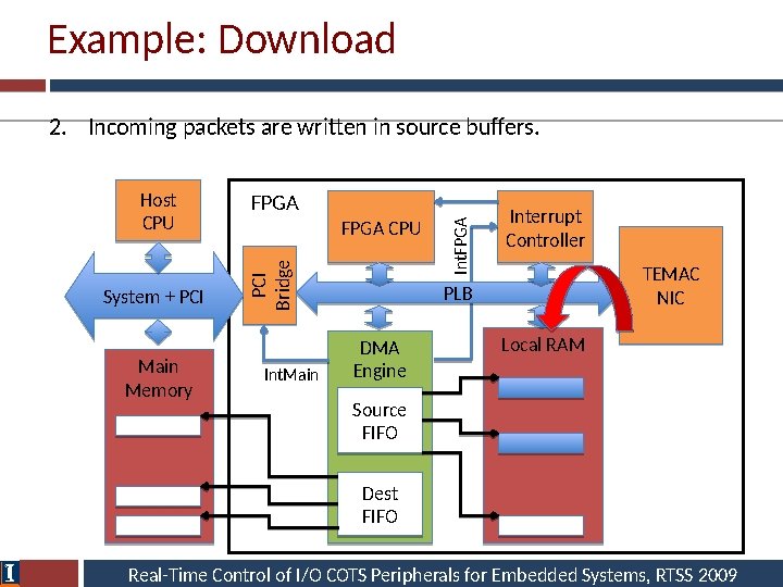
Example: Download 2. Incoming packets are written in source buffers. System + PCI Main Memory FPGA CPU Int. Main Int. FPGA PCI Bridge Host CPU Interrupt Controller TEMAC NIC PLB DMA Engine Local RAM Source FIFO Dest FIFO Real-Time Control of I/O COTS Peripherals for Embedded Systems, RTSS 2009
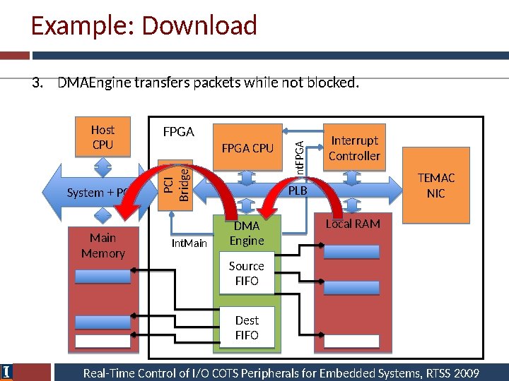
Example: Download 3. DMAEngine transfers packets while not blocked. System + PCI Main Memory FPGA CPU Int. Main Int. FPGA PCI Bridge Host CPU Interrupt Controller TEMAC NIC PLB DMA Engine Local RAM Source FIFO Dest FIFO Real-Time Control of I/O COTS Peripherals for Embedded Systems, RTSS 2009
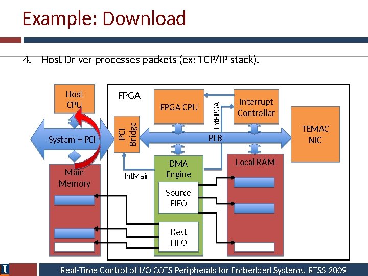
Example: Download 4. Host Driver processes packets (ex: TCP/IP stack). System + PCI Main Memory FPGA CPU Int. Main Int. FPGA PCI Bridge Host CPU Interrupt Controller TEMAC NIC PLB DMA Engine Local RAM Source FIFO Dest FIFO Real-Time Control of I/O COTS Peripherals for Embedded Systems, RTSS 2009
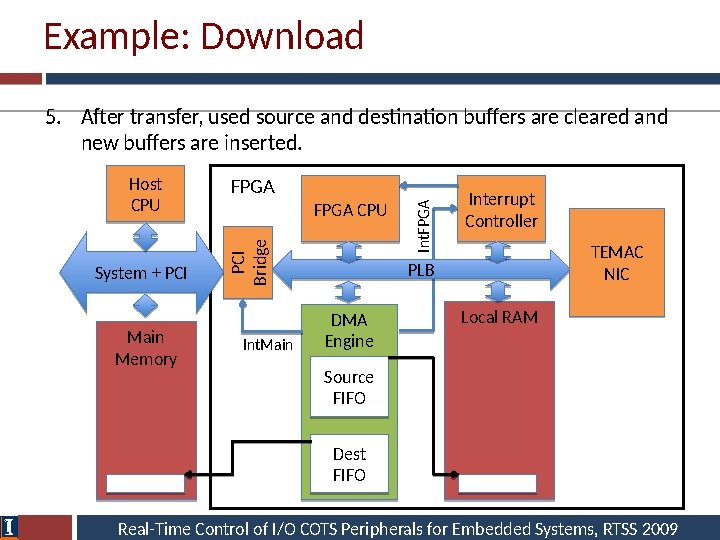
Example: Download 5. After transfer, used source and destination buffers are cleared and new buffers are inserted. System + PCI Main Memory FPGA CPU Int. Main Int. FPGA PCI Bridge Host CPU Interrupt Controller TEMAC NIC PLB DMA Engine Local RAM Source FIFO Dest FIFO Real-Time Control of I/O COTS Peripherals for Embedded Systems, RTSS 2009
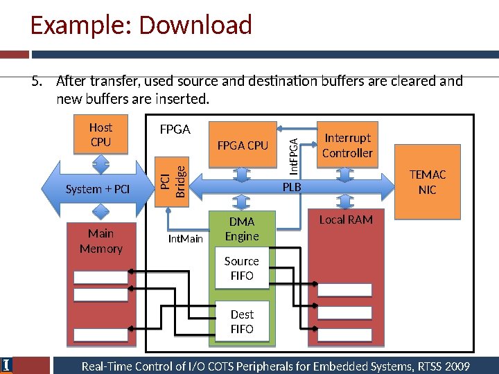
Example: Download 5. After transfer, used source and destination buffers are cleared and new buffers are inserted. System + PCI Main Memory FPGA CPU Int. Main Int. FPGA PCI Bridge Host CPU Interrupt Controller TEMAC NIC PLB DMA Engine Local RAM Source FIFO Dest FIFO Real-Time Control of I/O COTS Peripherals for Embedded Systems, RTSS 2009
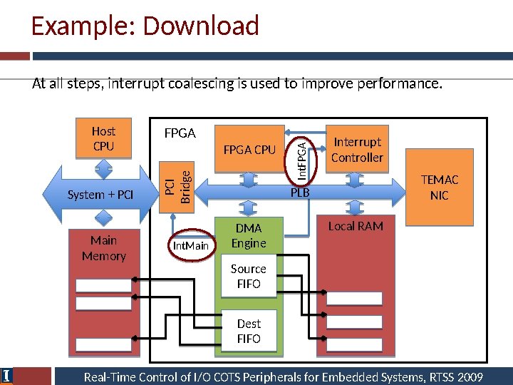
Example: Download At all steps, interrupt coalescing is used to improve performance. System + PCI Main Memory FPGA CPU Int. Main Int. FPGA PCI Bridge Host CPU Interrupt Controller TEMAC NIC PLB DMA Engine Local RAM Source FIFO Dest FIFO Real-Time Control of I/O COTS Peripherals for Embedded Systems, RTSS 2009
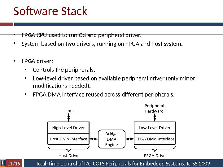
Software Stack • FPGA CPU used to run OS and peripheral driver. • System based on two drivers, running on FPGA and host system. • FPGA driver: • Controls the peripherals. • Low-level driver based on available peripheral driver (only minor modifications needed). • FPGA DMA Interface reused across different peripherals. 11/19 Real-Time Control of I/O COTS Peripherals for Embedded Systems, RTSS 2009
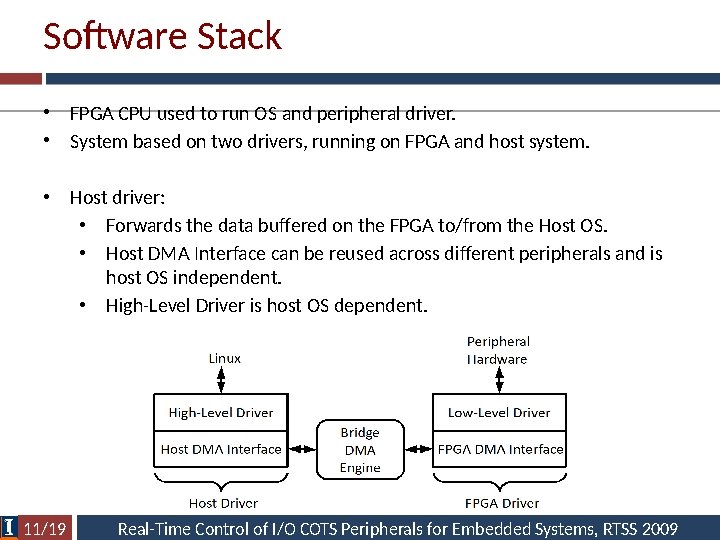
Software Stack • FPGA CPU used to run OS and peripheral driver. • System based on two drivers, running on FPGA and host system. • Host driver: • Forwards the data buffered on the FPGA to/from the Host OS. • Host DMA Interface can be reused across different peripherals and is host OS independent. • High-Level Driver is host OS dependent. 11/19 Real-Time Control of I/O COTS Peripherals for Embedded Systems, RTSS 2009
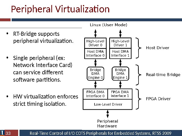
Peripheral Virtualization • RT-Bridge supports peripheral virtualization. • Single peripheral (ex: Network Interface Card) can service different software partitions. • HW virtualization enforces strict timing isolation. 33 Real-Time Control of I/O COTS Peripherals for Embedded Systems, RTSS 2009
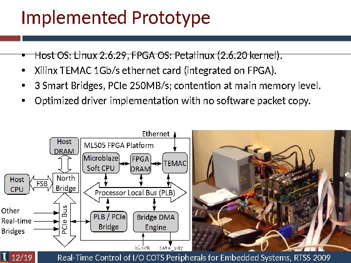
Implemented Prototype • • 12/19 Host OS: Linux 2. 6. 29, FPGA OS: Petalinux (2. 6. 20 kernel). Xilinx TEMAC 1 Gb/s ethernet card (integrated on FPGA). 3 Smart Bridges, PCIe 250 MB/s; contention at main memory level. Optimized driver implementation with no software packet copy. Real-Time Control of I/O COTS Peripherals for Embedded Systems, RTSS 2009
Flow Analysis • Main advantage: bus feasibility checked using well-known monoprocessor schedulability tests. • Servers are used to enforce transmission budgets for aperiodic traffic. • However, we pay in term of flow delay and on-bridge memory. • While a Real-Time Bridge is blocked, incoming network packets must be buffered in the FPGA RAM. – How much buffer space is needed (backlog)? – What is the maximum buffer time (delay)? • We devised a methodology based on real-time calculus to compute bounds on delay and buffer size. 13/19 Real-Time Control of I/O COTS Peripherals for Embedded Systems, RTSS 2009
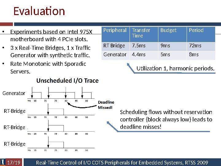
Evaluation • Experiments based on Intel 975 X motherboard with 4 PCIe slots. • 3 x Real-Time Bridges, 1 x Traffic Generator with synthetic traffic. • Rate Monotonic with Sporadic Servers. Peripheral Transfer Time Budget Period RT Bridge 7. 5 ms 9 ms 72 ms Generator 4. 4 ms 5 ms 8 ms Utilization 1, harmonic periods. Generator RT-Bridge Scheduling flows without reservation controller (block always low) leads to deadline misses! RT-Bridge 17/19 Real-Time Control of I/O COTS Peripherals for Embedded Systems, RTSS 2009
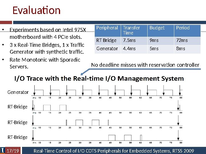
Evaluation Peripheral Transfer Budget Period • Experiments based on Intel 975 X Time motherboard with 4 PCIe slots. RT Bridge 7. 5 ms 9 ms 72 ms • 3 x Real-Time Bridges, 1 x Traffic Generator 4. 4 ms 5 ms 8 ms Generator with synthetic traffic. • Rate Monotonic with Sporadic No deadline misses with reservation controller Servers. Generator RT-Bridge 17/19 Real-Time Control of I/O COTS Peripherals for Embedded Systems, RTSS 2009
Reconfigurable Devices and Real-Time • Great deal of attention on reconfigurable FPGA for embedded and real-time systems – Pro: HW logic is (often) more predictable than SW executing on complex microarchitectures – Pro: HW logic is more efficient (per unit of chip area/power consumption) compared to GP CPU on parallel math crunching applications – somehow negated by GPU nowadays – Cons: Programming the HW is more complex • Huge amount of research on synthesis of FPGA logic from highlevel specification (ex: System. C). • How to use it: static design – Implement I/O, interconnects and all other PE on ASIC. – Use some portion of the chip for a programmable FPGA processor. 42 / 50
Reconfigurable FPGA • How to use it: dynamic design – Implement I/O and interconnects as fixed logic on FPGA. – Use the rest of the FPGA area for reconfigurable HW tasks. • HW Task – Period, deadline, wcet as SW tasks. – Additionally has an area requirement. – Requirement depends on the area model. 43 / 50
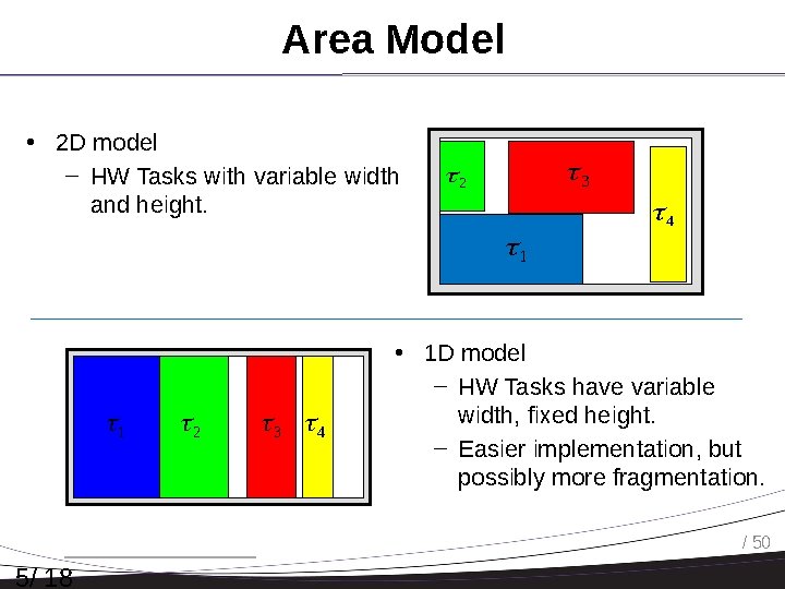
Area Model • 2 D model – HW Tasks with variable width and height. 3 2 4 1 1 2 3 4 • 1 D model – HW Tasks have variable width, fixed height. – Easier implementation, but possibly more fragmentation. / 50 5/ 18
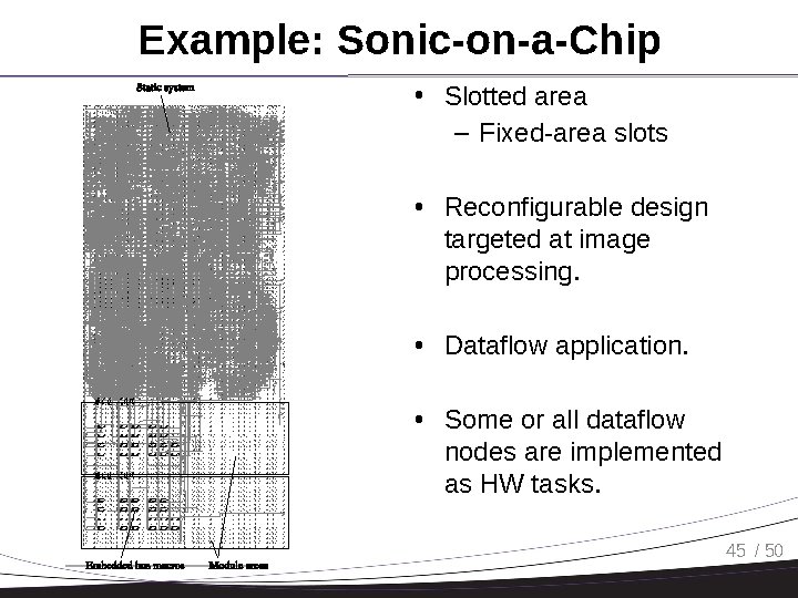
Fig. 10 illustrates the placed and routed static design in the Virtex-4 XC 4 VLX 25 device. Two module regions are defined, which are aligned with the clock regions in order to use the regional clock buffers [21] for locally generated However, using reserved routing enables bus macros to be embedded within the module region. This is achieved by designating all routing as static in the CLB tile, where static signals connect to the macro, as shown in Fig. 11. Embedded macros increase connectivity and floorplanning choices. Example: Sonic-on-a-Chip • Slotted area 5. 4 Configuration overhead – Fixed-area slots The use of a read– modify– write operation to configure partial bitstream comes at a cost of increased configuration time. In the applications examined, the operational time of an instantiated module is in theorder of seconds to minutes or even hours; thus the reconfiguration time overhead in both direct and mergeconfigurations is orders of magnitude • Reconfigurable design targeted at image processing. • Dataflow application. • Some or all dataflow nodes are implemented as HW tasks. 45 / 50 Fig. 10 Sonic-on-a-Chip in an Virtex-4 Fig. 11 Embedded bus macros
Main Constraints • Interconnects constraints – HW tasks must be interfaced to the interconnects. – Fixed wire connections: bus macros. – The 2 D model is very hard to implement. • Reconfiguration constraints – With dynamic reconfiguration a HW task can be reconfigured at run-time, but… – … reconfiguration takes a long time. – Solution: no HW task preemption. – However, we can still activate/deactivate HW tasks based on current application mode. 46 / 50
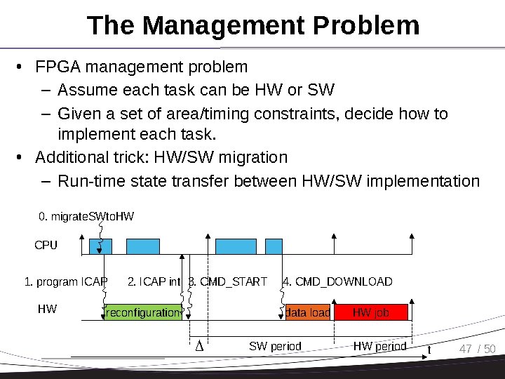
The Management Problem • FPGA management problem – Assume each task can be HW or SW – Given a set of area/timing constraints, decide how to implement each task. • Additional trick: HW/SW migration – Run-time state transfer between HW/SW implementation 0. migrate. SWto. HW CPU 1. program ICAP HW 2. ICAP int 3. CMD_START reconfiguration 4. CMD_DOWNLOAD data load SW period HW job HW period t 47 / 50
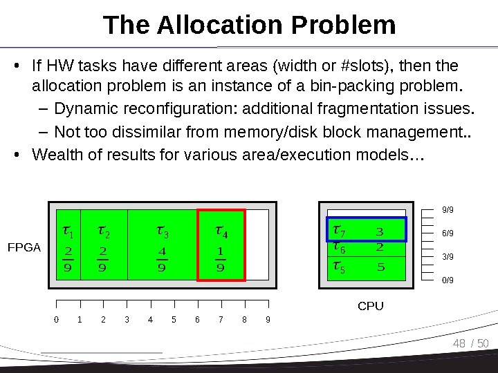
The Allocation Problem • If HW tasks have different areas (width or #slots), then the allocation problem is an instance of a bin-packing problem. – Dynamic reconfiguration: additional fragmentation issues. – Not too dissimilar from memory/disk block management. . • Wealth of results for various area/execution models… 9/9 FPGA 1 2 3 4 2 9 4 9 1 9 7 6 5 3 2 5 6/9 3/9 0/9 CPU 0 1 2 3 4 5 6 7 8 9 48 / 50
Assignments • Next Monday 8: 00 AM: literature review. • Fix/extend the introduction and project plan based on provided comments. • Include an extended comparison with related work. – How each related work tackled your research problem. – How you are going to tackle the problem. – Why your approach is worthwhile compared to related work. – What are the limits of your approach compared to related work. – You do not need to describe your complete solution (or results), but do include some technical details – you need to show that you have a clear direction for the project. – Of course you also need to show that you read the related work… 49 / 50
Final • Final: scheduled for December 12 • Let me know if you have any conflict. 50 / 50
- Slides: 50