
ECE 651 Digital Signal Processing I Digital IIR
- Slides: 24
ECE 651 Digital Signal Processing I Digital IIR Filter Design
Ø Introduction Ø Some Preliminaries on Analog Filters Ø Digital IIR Filter Design (s – z) Ø q Impulse Invariance Transformation q Bilinear Transformation Frequency Band Transformations q Analog Domain (s – s ) q Digital Domain (z – z)
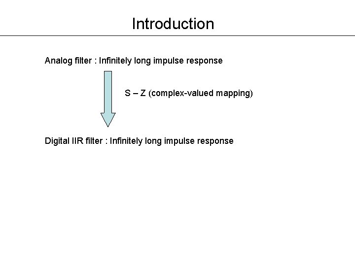
Introduction Analog filter : Infinitely long impulse response S – Z (complex-valued mapping) Digital IIR filter : Infinitely long impulse response
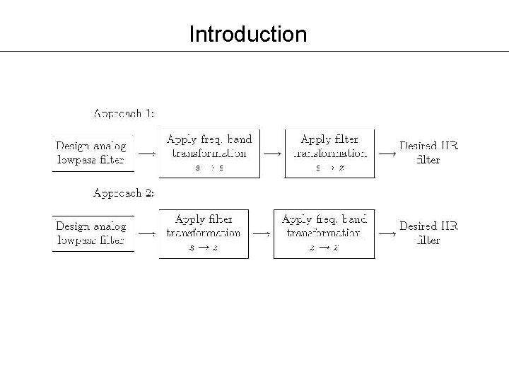
Introduction
Introduction Advantages • Analog filter design tables available • Filter transformation (s – z) tables available • Frequency band transformation (s – s / z – z) available Disadvantages • No control over the phase characteristics of the IIR filter • Magnitude – only design
Introduction Other Design Approaches • Simultaneously approximate both the magnitude and the phase response • Require advanced optimization tools • Not covered in the class
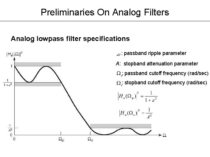
Preliminaries On Analog Filters Analog lowpass filter specifications : passband ripple parameter A: stopband attenuation parameter : passband cutoff frequency (rad/sec) : stopband cutoff frequency (rad/sec)
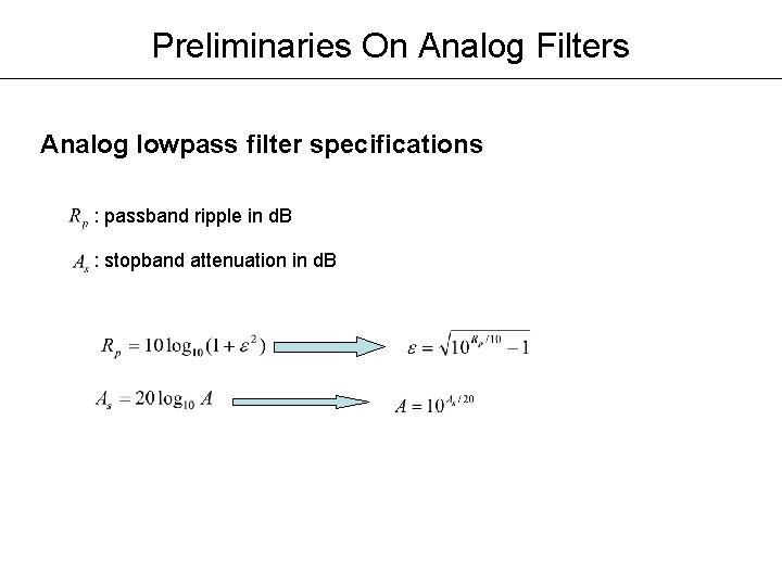
Preliminaries On Analog Filters Analog lowpass filter specifications : passband ripple in d. B : stopband attenuation in d. B
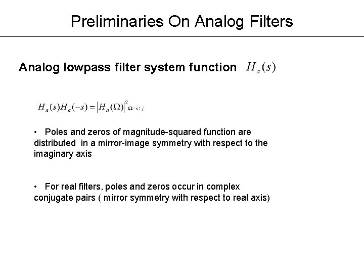
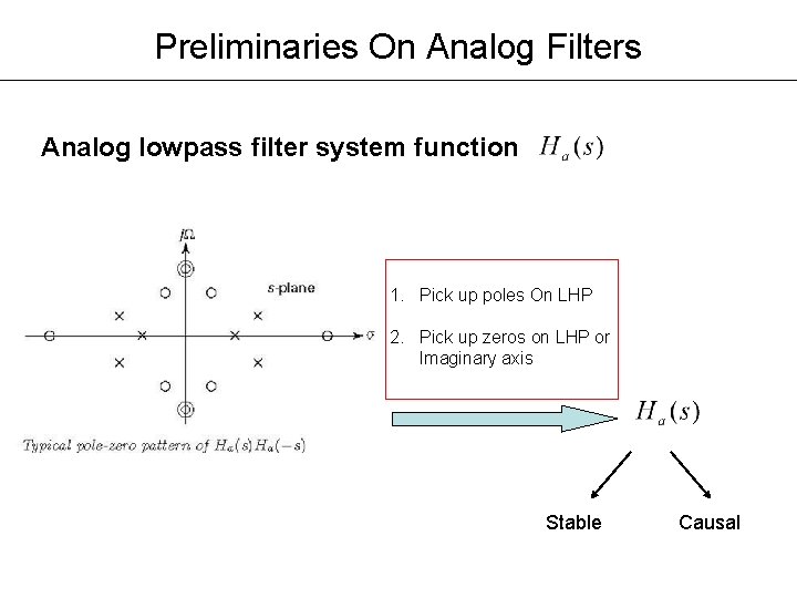
Preliminaries On Analog Filters Analog lowpass filter system function • Poles and zeros of magnitude-squared function are distributed in a mirror-image symmetry with respect to the imaginary axis • For real filters, poles and zeros occur in complex conjugate pairs ( mirror symmetry with respect to real axis)
Preliminaries On Analog Filters Analog lowpass filter system function 1. Pick up poles On LHP 2. Pick up zeros on LHP or Imaginary axis Stable Causal
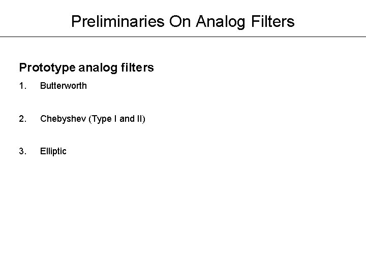
Preliminaries On Analog Filters Prototype analog filters 1. Butterworth 2. Chebyshev (Type I and II) 3. Elliptic
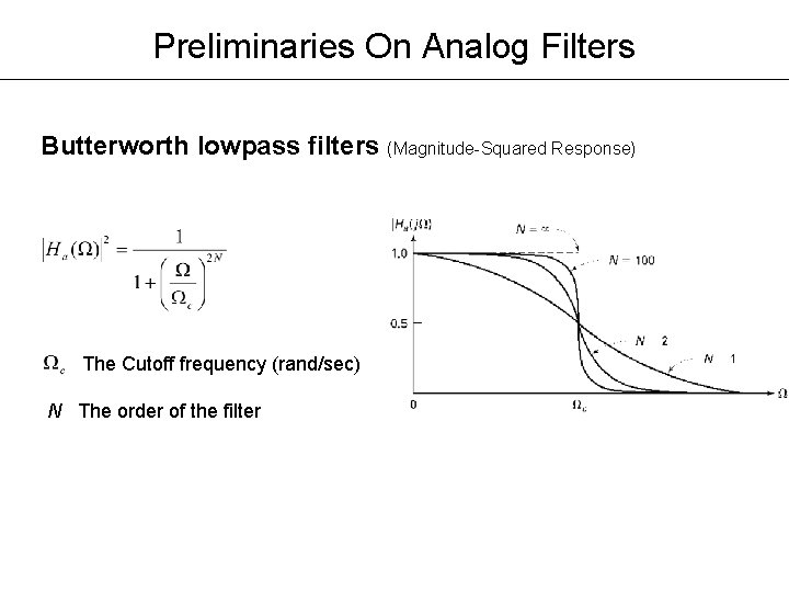
Preliminaries On Analog Filters Butterworth lowpass filters (Magnitude-Squared Response) The Cutoff frequency (rand/sec) N The order of the filter
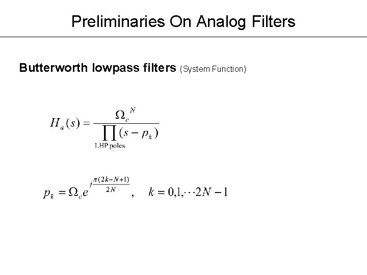
Preliminaries On Analog Filters Butterworth lowpass filters (System Function)
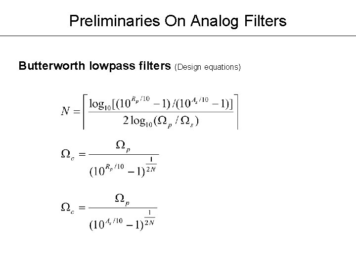
Preliminaries On Analog Filters Butterworth lowpass filters (Design equations)
Digital IIR Filter Design S - Z transformation • Complex-valued mappings • Derived by preserving different aspects of analog filters and digital filters
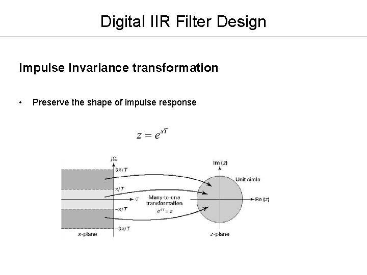
Digital IIR Filter Design Impulse Invariance transformation • Preserve the shape of impulse response
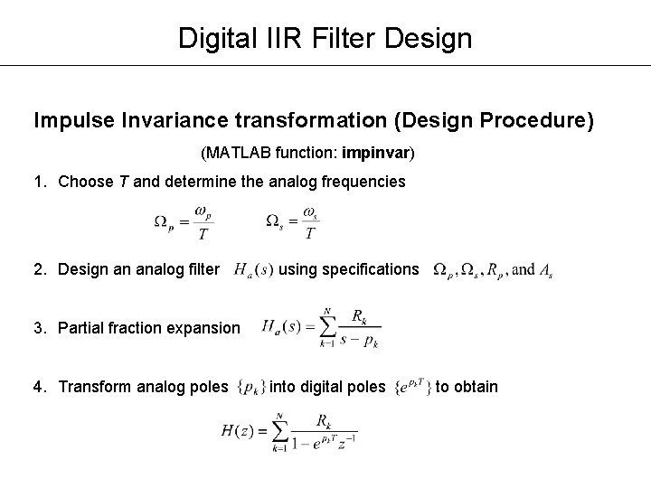
Digital IIR Filter Design Impulse Invariance transformation (Design Procedure) (MATLAB function: impinvar) 1. Choose T and determine the analog frequencies 2. Design an analog filter using specifications 3. Partial fraction expansion 4. Transform analog poles into digital poles to obtain
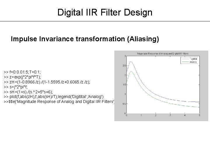
Digital IIR Filter Design Impulse Invariance transformation (Aliasing) >> f=0: 0. 01: 5; T=0. 1; >> z=exp(j*2*pi*f*T); >> z. H=(1 -0. 8966. /z). /(1 -1. 5595. /z+0. 6065. /z); >> s=j*2*pi*f; >> s. H=(1+s). /(s. ^2+5*s+6); >> plot(f, abs(z. H), f, abs(s. H)/T); legend('Digitital', 'Analog') >>title('Magnitude Response of Analog and Digital IIR Filters')
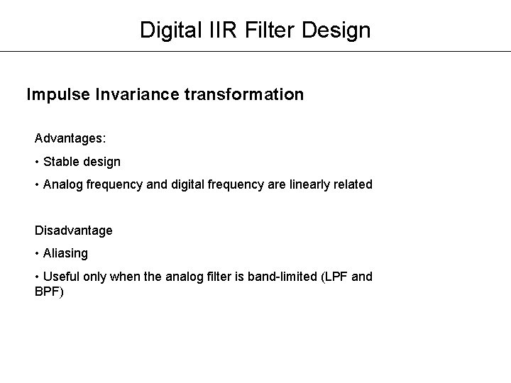
Digital IIR Filter Design Impulse Invariance transformation Advantages: • Stable design • Analog frequency and digital frequency are linearly related Disadvantage • Aliasing • Useful only when the analog filter is band-limited (LPF and BPF)
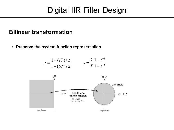
Digital IIR Filter Design Bilinear transformation • Preserve the system function representation
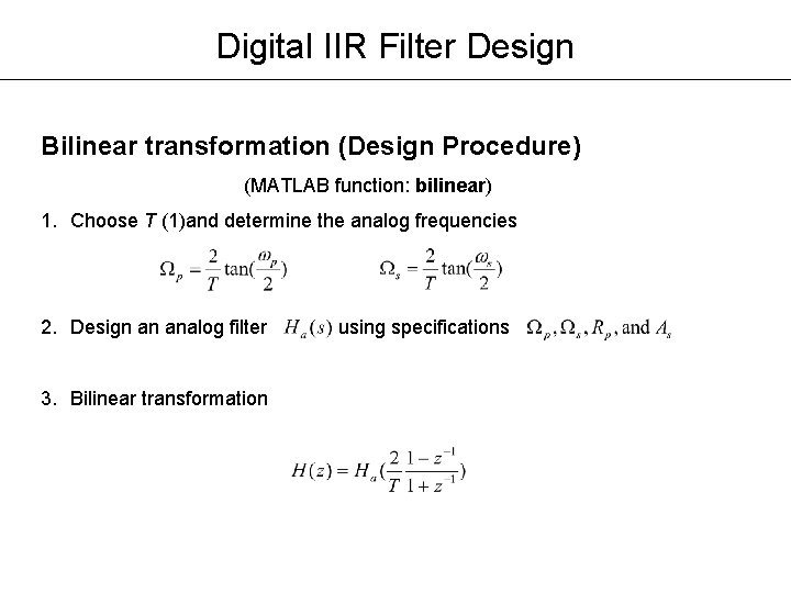
Digital IIR Filter Design Bilinear transformation (Design Procedure) (MATLAB function: bilinear) 1. Choose T (1)and determine the analog frequencies 2. Design an analog filter 3. Bilinear transformation using specifications
Digital IIR Filter Design Bilinear transformation Advantages • Stable design • No aliasing • No restriction on the type of filters that can be transformed
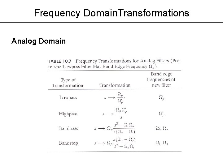
Frequency Domain. Transformations Analog Domain
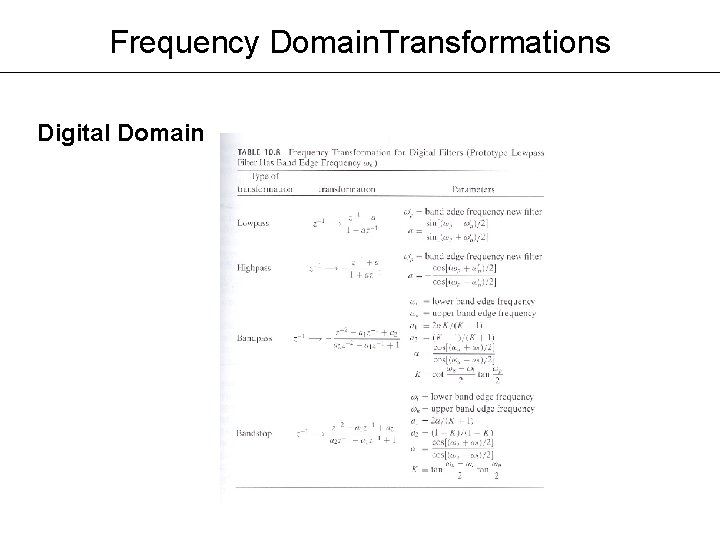
Frequency Domain. Transformations Digital Domain