
ECE 553 TESTING AND TESTABLE DESIGN OF DIGITAL
ECE 553: TESTING AND TESTABLE DESIGN OF DIGITAL SYSTES Logic Modeling
Overview • Motivation • Logic Modeling – Model types – Models at different levels of abstractions – Models and definitions • Summary 9/15/2020 2
Motivation – Models are often easier to work with – Models are portable – Models can be used for simulation, thus avoiding expensive hardware/actual circuit implementation – Nearly all engineering systems are studied using models – All the above apply for logic as well as for fault modeling 9/15/2020 3
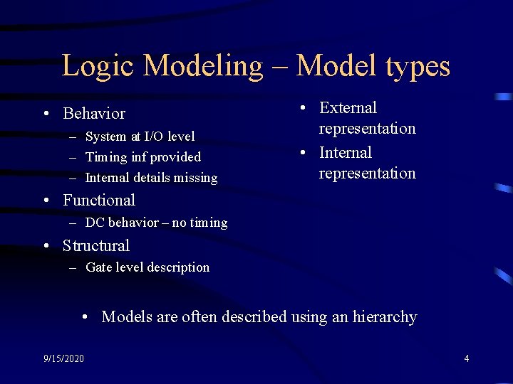
Logic Modeling – Model types • Behavior – System at I/O level – Timing inf provided – Internal details missing • External representation • Internal representation • Functional – DC behavior – no timing • Structural – Gate level description • Models are often described using an hierarchy 9/15/2020 4
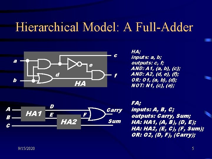
Hierarchical Model: A Full-Adder c a e d b A B C HA 1 9/15/2020 D E HA HA 2 F f Carry Sum HA; inputs: a, b; outputs: c, f; AND: A 1, (a, b), (c); AND: A 2, (d, e), (f); OR: O 1, (a, b), (d); NOT: N 1, (c), (e); FA; inputs: A, B, C; outputs: Carry, Sum; HA: HA 1, (A, B), (D, E); HA: HA 2, (E, C), (F, Sum); OR: O 2, (D, F), (Carry); 5
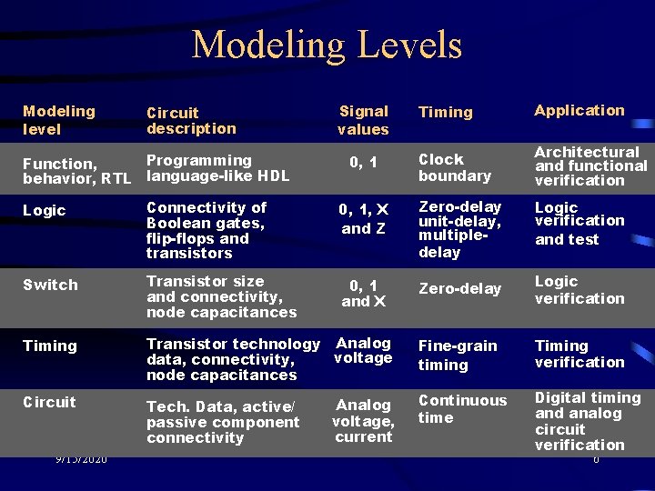
Modeling Levels Modeling level Circuit description Programming Function, behavior, RTL language-like HDL Signal values 0, 1 Timing Application Clock boundary Architectural and functional verification Logic Connectivity of Boolean gates, flip-flops and transistors 0, 1, X and Z Zero-delay unit-delay, multipledelay Logic verification and test Switch Transistor size and connectivity, node capacitances 0, 1 and X Zero-delay Logic verification Timing Transistor technology Analog voltage data, connectivity, node capacitances Fine-grain timing Timing verification Circuit Tech. Data, active/ passive component connectivity Continuous time Digital timing and analog circuit verification 9/15/2020 Analog voltage, current 6
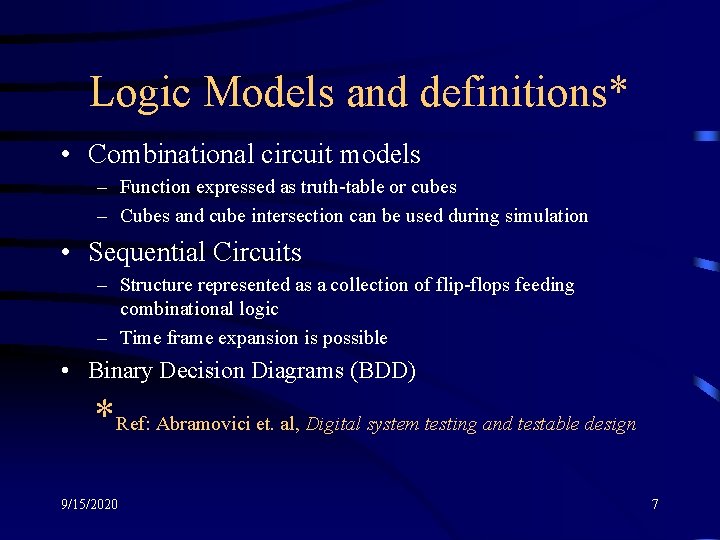
Logic Models and definitions* • Combinational circuit models – Function expressed as truth-table or cubes – Cubes and cube intersection can be used during simulation • Sequential Circuits – Structure represented as a collection of flip-flops feeding combinational logic – Time frame expansion is possible • Binary Decision Diagrams (BDD) *Ref: Abramovici et. al, Digital system testing and testable design 9/15/2020 7
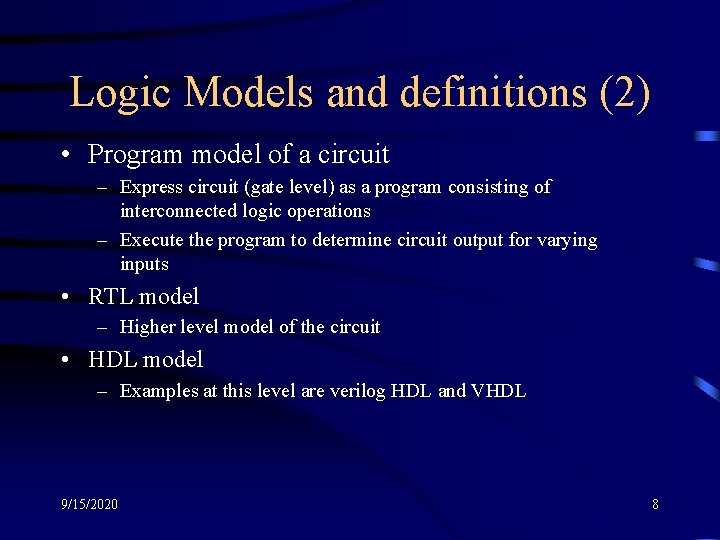
Logic Models and definitions (2) • Program model of a circuit – Express circuit (gate level) as a program consisting of interconnected logic operations – Execute the program to determine circuit output for varying inputs • RTL model – Higher level model of the circuit • HDL model – Examples at this level are verilog HDL and VHDL 9/15/2020 8
Logic Models and definitions (3) • Structural model – External representation in the form of netlist – Examples of this are uw format, iscas format, EDIF, … – Some keywords used in such representation • • 9/15/2020 Primary inputs and Primary outputs Gates: AND, OR, NOT, … Storage: latch, flip-flop Connections: lines, nets Fanin: number of inputs to a gate Fanout: number of lines a signal feeds Fanoutfree circuit: every line or gate has a fanout of one 9
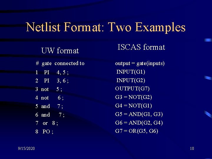
Netlist Format: Two Examples UW format # gate connected to 1 2 3 4 5 6 7 8 9/15/2020 PI 4, 5 ; PI 3, 6 ; not 5 ; not 6 ; and 7; or 8 ; PO ; ISCAS format output = gate(inputs) INPUT(G 1) INPUT(G 2) OUTPUT(G 7) G 3 = NOT(G 2) G 4 = NOT(G 1) G 5 = AND(G 1, G 3) G 6 = AND(G 2, G 4) G 7 = OR(G 5, G 6) 10
Logic Models and definitions (4) • Structural model – Internal representation in the form of tables • Tables of gates and storage elements (names) • Tables of connections • Tables of fanin and fanouts – Objective is to make the storage and search processes (integral part of simulation) more efficient – Knowledge of data structures and algorithms is very useful 9/15/2020 11
Logic Models and definitions (5) • Additional useful terms – – – 9/15/2020 Graph representation Reconvergent fanouts Stems and branches Logic levels in a circuit “levelization” of a circuit 12
Summary • Modeling of logic circuit offers many advantages • Many modeling levels exist and are used • Gate level models are most prevalent in logic testing 9/15/2020 13
- Slides: 13