
ECE 5221 Personal Communication Systems Prepared by Dr
ECE 5221 Personal Communication Systems Prepared by: Dr. Ivica Kostanic Lecture 24 – Basics of 3 G – UMTS (3) Spring 2011
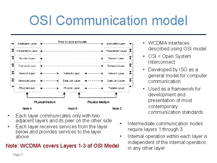
OSI Communication model • WCDMA interfaces described using OSI model • OSI = Open System Interconnect • Developed by ISO as a general model for computer communication • • Each layer communicates only with two adjacent layers and its peer on the other side Each layer receives services from the layer below and provides services to the layer above Note: WCDMA covers Layers 1 -3 of OSI Model Page 2 • Used as a framework for development and presentation of most contemporary communication standards • • Intermediate communication nodes require layers 1 through 3 Internal operation within each layer is independent of the internal operation in any other layer

UMTS Protocol stack • • • UMTS offers new Access stratum protocol stack Non-Access Stratum is largely inherited from GSM First three layers of the protocol stack are part of UTRAN Note: SMS exists on both circuit switched and packet switched side Page 3
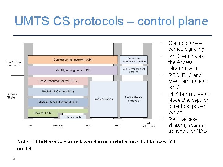
UMTS CS protocols – control plane • • • Control plane – carries signaling RNC terminates the Access Stratum (AS) RRC, RLC and MAC terminate at RNC PHY terminates at Node B except for outer loop power control RAN (access stratum) acts as transport for NAS Note: UTRAN protocols are layered in an architecture that follows OSI model 4
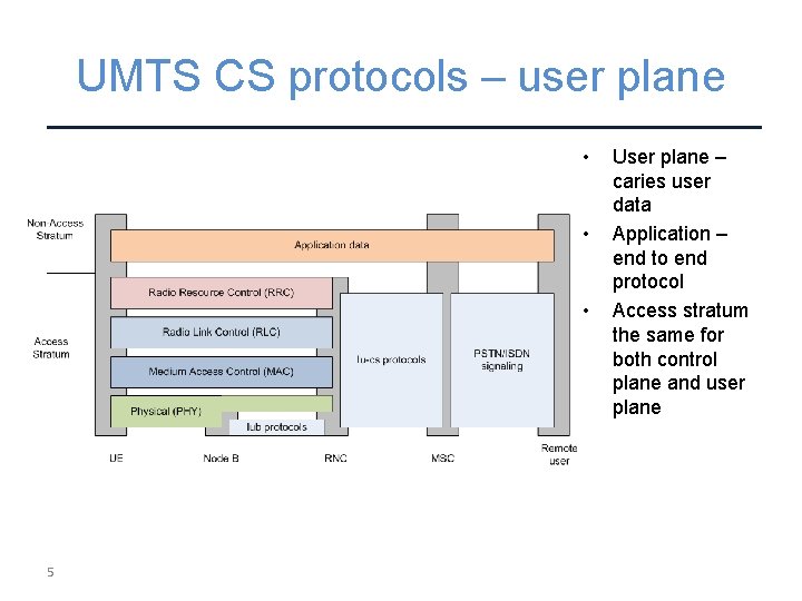
UMTS CS protocols – user plane • • • 5 User plane – caries user data Application – end to end protocol Access stratum the same for both control plane and user plane

UMTS PS protocols – control plane • • • 6 Control plane for packet data Very similar to control plane for PS Identical access stratum
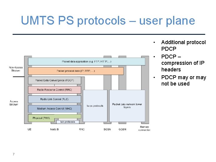
UMTS PS protocols – user plane • • • 7 Additional protocol PDCP – compression of IP headers PDCP may or may not be used
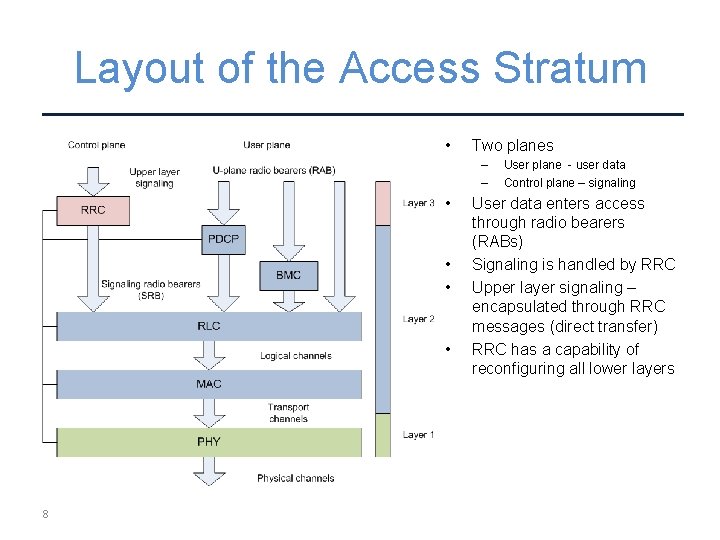
Layout of the Access Stratum • Two planes – – • • 8 User plane - user data Control plane – signaling User data enters access through radio bearers (RABs) Signaling is handled by RRC Upper layer signaling – encapsulated through RRC messages (direct transfer) RRC has a capability of reconfiguring all lower layers
Part 6 ELEMENTS OF PHY LAYER PROCESSING 9
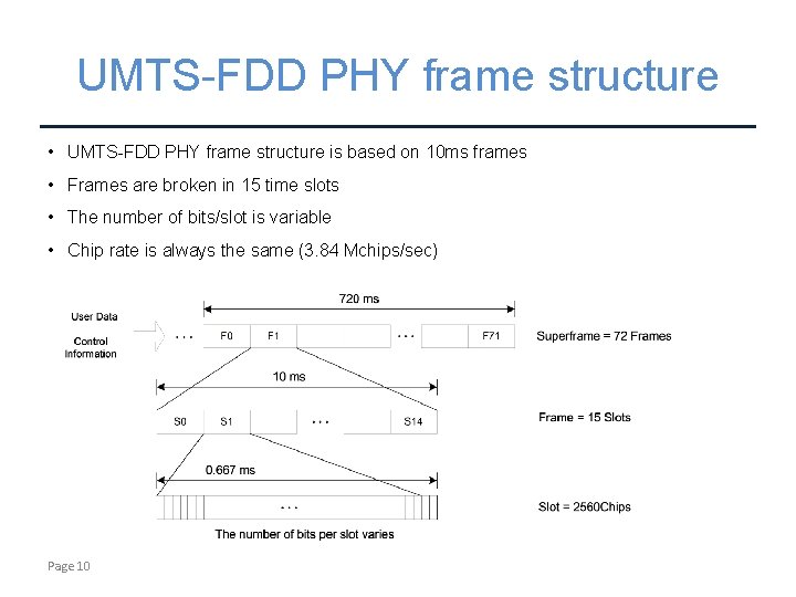
UMTS-FDD PHY frame structure • UMTS-FDD PHY frame structure is based on 10 ms frames • Frames are broken in 15 time slots • The number of bits/slot is variable • Chip rate is always the same (3. 84 Mchips/sec) Page 10
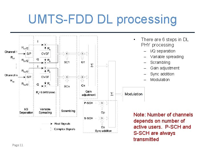
UMTS-FDD DL processing • There are 6 steps in DL PHY processing – – – I/Q separation Variable spreading Scrambling Gain adjustment Sync addition Modulation Note: Number of channels depends on number of active users. P-SCH and S-SCH are always transmitted Page 11
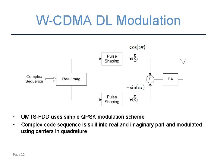
W-CDMA DL Modulation • • UMTS-FDD uses simple QPSK modulation scheme Complex code sequence is split into real and imaginary part and modulated using carriers in quadrature Page 12
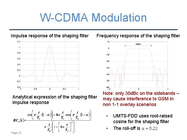
W-CDMA Modulation Impulse response of the shaping filter Frequency response of the shaping filter Analytical expression of the shaping filter impulse response Note: only 30 d. Bc on the sidebands – may cause interference to GSM in non 1 -1 overlay scenarios • • Page 13 UMTS-FDD uses root-raised cosine for the shaping filter The roll-off is a = 0. 22
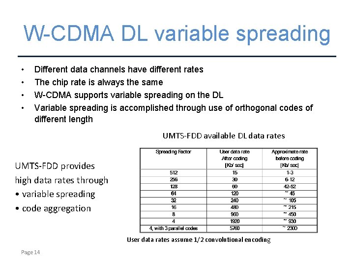
W-CDMA DL variable spreading • • Different data channels have different rates The chip rate is always the same W-CDMA supports variable spreading on the DL Variable spreading is accomplished through use of orthogonal codes of different length UMTS-FDD available DL data rates UMTS-FDD provides high data rates through • variable spreading • code aggregation User data rates assume 1/2 convolutional encoding Page 14
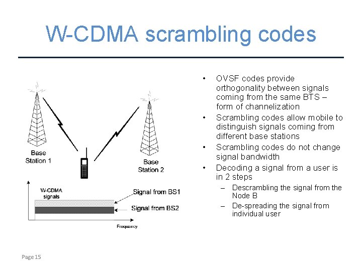
W-CDMA scrambling codes • • OVSF codes provide orthogonality between signals coming from the same BTS – form of channelization Scrambling codes allow mobile to distinguish signals coming from different base stations Scrambling codes do not change signal bandwidth Decoding a signal from a user is in 2 steps – Descrambling the signal from the Node B – De-spreading the signal from individual user Page 15
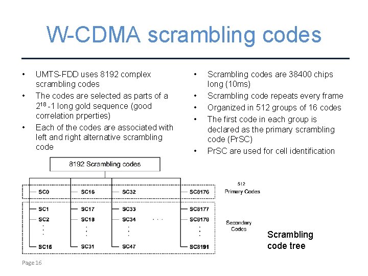
W-CDMA scrambling codes • • • UMTS-FDD uses 8192 complex scrambling codes The codes are selected as parts of a 218 -1 long gold sequence (good correlation prperties) Each of the codes are associated with left and right alternative scrambling code • • • Scrambling codes are 38400 chips long (10 ms) Scrambling code repeats every frame Organized in 512 groups of 16 codes The first code in each group is declared as the primary scrambling code (Pr. SC) Pr. SC are used for cell identification Scrambling code tree Page 16
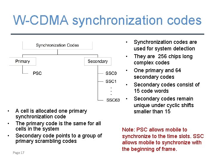
W-CDMA synchronization codes • • A cell is allocated one primary synchronization code The primary code is the same for all cells in the system Secondary code points to a group of primary scrambling codes Page 17 Synchronization codes are used for system detection They are 256 chips long complex codes One primary and 64 secondary codes Secondary codes consist of 15 code words Secondary codes remain unique under cyclic shifts smaller than 15 Note: PSC allows mobile to synchronize to the time slots. SSC allows mobile to synchronize with the beginning of frame.
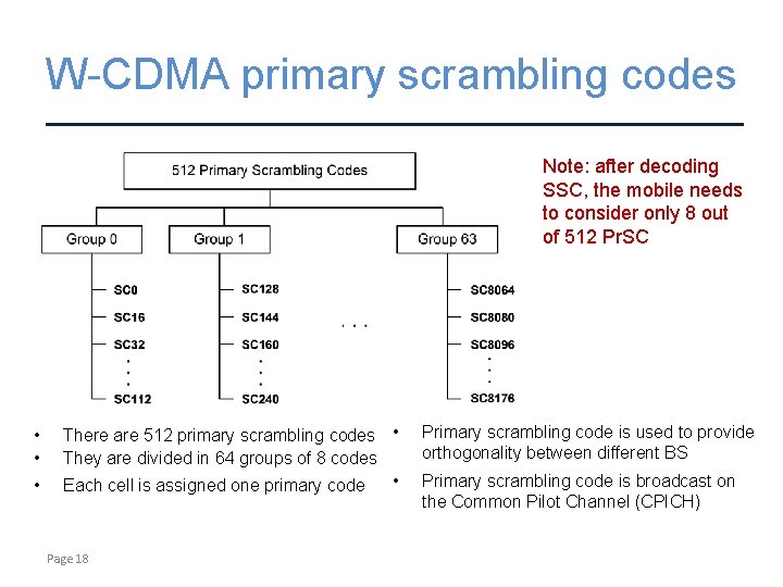
W-CDMA primary scrambling codes Note: after decoding SSC, the mobile needs to consider only 8 out of 512 Pr. SC • • • There are 512 primary scrambling codes • They are divided in 64 groups of 8 codes • Each cell is assigned one primary code Page 18 Primary scrambling code is used to provide orthogonality between different BS Primary scrambling code is broadcast on the Common Pilot Channel (CPICH)
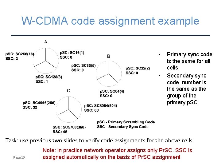
W-CDMA code assignment example • • Primary sync code is the same for all cells Secondary sync code number is the same as the group of the primary p. SC Task: use previous two slides to verify code assignments for the above cells Page 19 Note: in practice network operator assigns only Pr. SC. SSC is assigned automatically on the basis of Pr. SC assignment
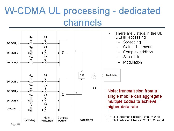
W-CDMA UL processing - dedicated channels • There are 5 steps in the UL DCHs processing – Spreading – Gain adjustment – Complex addition – Scrambling – Modulation Note: transmission from a single mobile can aggregate multiple codes to achieve higher data rate DPDCH - Dedicated Physical Data Channel DPCCH - Dedicated Physical Control Channel Page 20
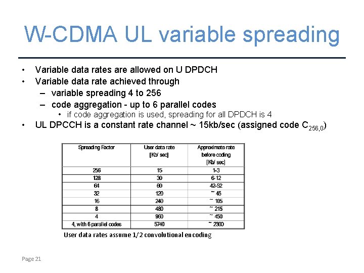
W-CDMA UL variable spreading • • Variable data rates are allowed on U DPDCH Variable data rate achieved through – variable spreading 4 to 256 – code aggregation - up to 6 parallel codes • if code aggregation is used, spreading for all DPDCH is 4 • UL DPCCH is a constant rate channel ~ 15 kb/sec (assigned code C 256, 0) User data rates assume 1/2 convolutional encoding Page 21
- Slides: 21