ECE 4951 Lecture 1 Programmable Logic Controllers Course

ECE 4951 Lecture 1: Programmable Logic Controllers

Course Objectives • ABET OBJECTIVES • WORK WITH INDUSTRY TO DEVELOP: – Scope and Specification – Budget – Design • DELIVER WRITTEN AND ORAL REPORTS AT UMD

PROJECTS • MP#1: Hydro Automation – Develop a PLC based control automation scheme for Winton Hydro (Ely, MN) • MP#2: Power Plant Educational Demo – Develop a PLC based control and data acquisition system for a model power plant • UMD#1: Automated Data Acquisition for Medical School – Develop hardware and software to broadcast metering data from Med. School to ethernet and collect for display and archiving

Skill Sets • MP#1: – PLC programming – Ability to learn MP control Schemes – Ability to work a fast track job • MP#2: – PLC programming – Mechanical ability – Ability to visualize and implement an open-ended spec • UMD#1: – Internet protocols – Software development – Data base development

PLC’s Are. . . • Similar to a Microcontroller: – Microprocessor Based – Onboard Memory for Storing Programs – Special Programming Language: Ladder Logic – Input/Output Ports

PLC’s Are. . . • Dissimilar to Microcontrollers: – Intended for Industrial Applications (High Power) – I/O Designed to interface with Control Relays – Emphasis on Maximum Reliability

PLC’s • Widely Applied in Every Industry • Were Developed to Simplify the Implementation of Control Automation Systems in Plants and Assembly Lines • Designed to Minimize the Number of Control Relays in a Process and Maximize the Ways Relays can be Used • First Applied to Automobile Industry in the Late 1960’s • Flexible, Reliable and Low Cost

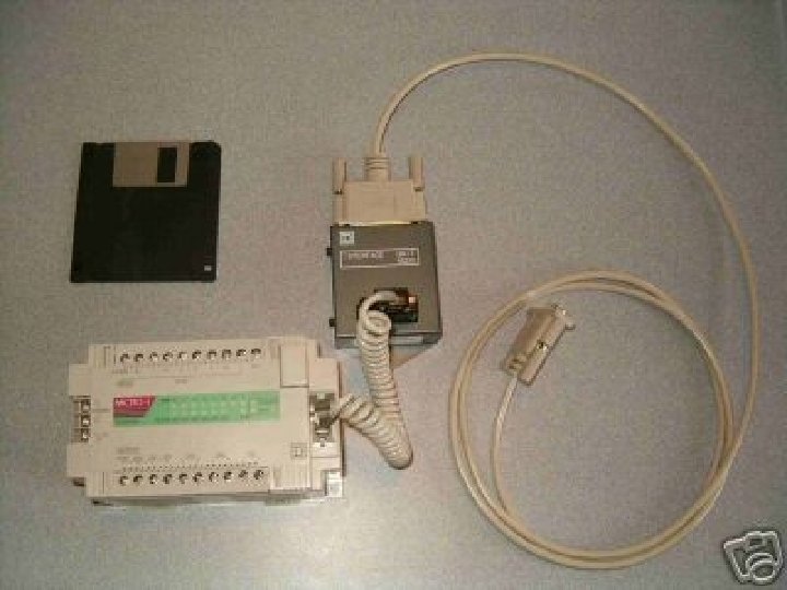
PLC Components

I/O Modules • Input Modules: Input Signals can be AC or DC, Analog or Digital • Output Modules: Outputs are either AC or DC Analog Signals (Although it is possible to ‘Construct’ Digital Outputs) • Modern PLC’s have Expansion Ports to Increase the Number of Available Inputs and Outputs
 –")
Examples of I/O Signals • Inputs: – Pushbutton (Energizing or Grounding an Input) – Relay Contact Output – DC Voltage Level – Digital Logic Signal (+5 V or 0 V, etc) • Outputs: – 24 V ac – 120 Vdc – etcetera

PLC’s Use Ladder Logic • Ladder Logic Diagrams Provide a Method to Symbolically Show How Relay Control Schemes are Implemented • Relay Contacts and Coils, Inputs and Outputs lie on “Rungs” Between the Positive and Ground Rails

Example of Ladder Diagram

Relays • In General, Relays Transform a Control Signal into a Control Action • Relays Provide: – Isolation Between Input and Output – Leverage (Small Signal Can Control Large Action) – Automation (Minimize Human Interaction with a Control Process)

Relay Components

Basic Relay Symbols

Relay Applications • Relays can be Designed to Perform Many Functions – Detect Out of Limit Conditions on Voltages and Currents – Start Motors – Prevent Motors from Over Heating – Control Assembly Lines – Adjust Lighting

References • Skvarenina/De. Witt, Electrical Power and Controls, Pearson-Prentice Hall, 2004
- Slides: 18