ECE 448 Lecture 13 FPro Video Subsystem Sprite

ECE 448 Lecture 13 FPro Video Subsystem: Sprite Core ECE 448 – FPGA and ASIC Design with VHDL George Mason University

Required Reading • P. Chu, FPGA Prototyping by VHDL Examples Chapter 21. 2, FPro Video IP Core Chapter 22, Sprite Core • Source Code of Examples http: //academic. csuohio. edu/chu_p/rtl/fpga_mcs_vhdl. html • Basys 3 FPGA Board Reference Manual 7. VGA Port ECE 448 – FPGA and ASIC Design with VHDL 2
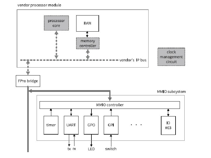

FPro System Memory Map 22 -bit word space, 24 -bit byte space 0 x xxxx xmmm mmma aaaa 64 MMIO Cores, each with 25 -word address space 11 aaaa aaaa 1 Frame Buffer Core, with 220 -word address space 10 xxxv vvaa aaaa 8 Video Cores, each with 214 -word address space ECE 448 – FPGA and ASIC Design with VHDL 5

Two Types of FPro Video Cores e. g. . color-to-grayscale conversion ECE 448 – FPGA and ASIC Design with VHDL 6

Blending • A process to combine two video frames into a single frame • Two frames are treated as two vertical layers • Bottom layer: background frame • Top layer: foreground frame ECE 448 – FPGA and ASIC Design with VHDL 7

Chroma-Key Blending Background Frame ECE 448 – FPGA and ASIC Design with VHDL Foreground Frame 8

Chroma-Key Blending • A technique to display a selective region of foreground frame on top of the background frame • A special preselected color is defined as the chroma key • The chroma key is used as the “background color” of a foreground frame • When two frames are blended, the pixels with the chroma key of the foreground frame are replaced by the corresponding pixels of the background frame ECE 448 – FPGA and ASIC Design with VHDL 9

Chroma-Key Blending r = f if f ≠ CK = b otherwise r – blended result f – color of a foreground pixel b – color of a background pixel CK – chroma key ECE 448 – FPGA and ASIC Design with VHDL 10

Chroma-Key Blending Background Frame ECE 448 – FPGA and ASIC Design with VHDL Foreground Frame 11
・b r –")
�� Blending r = �� ・ f + (1 - �� )・b r – blended result f – color of a foreground pixel b – color of a background pixel �� – “opacity level” of the foreground frame 0. 0 ≤ �� ≤ 1. 0 opacity = only foreground color displayed 0. 0 opacity = only background color displayed ECE 448 – FPGA and ASIC Design with VHDL 12
 ・")
Chroma-Key �� Blending r = �� ・ f + (1 - �� ) ・ b if f ≠ CK = b otherwise r – blended result f – color of a foreground pixel b – color of a background pixel CK – chroma key �� – “opacity level” of the foreground frame 0. 0 ≤ �� ≤ 1. 0 opacity = only foreground color displayed 0. 0 opacity = only background color displayed ECE 448 – FPGA and ASIC Design with VHDL 13

Mouse Pointer Sprite 12 pixels by 20 pixels ECE 448 – FPGA and ASIC Design with VHDL 14

Sprite • In computer graphics, a sprite is a small bitmap image that is integrated into a larger scene • A bitmap defines a rectangular area and the color for each pixel in the display area • A sprite is a small bitmap, for which a display area is a tiny fraction of the frame ECE 448 – FPGA and ASIC Design with VHDL 15

Block Diagram of a Sprite Generation Circuit ECE 448 – FPGA and ASIC Design with VHDL 16

Sprite RAM • Stores the pixel data of the bitmap • Memory word width = color depth • One dimensional array address (xr, yr) = yr * Hs + xr where the dimensions of the bitmap are Hs and Vs • Typically, Hs = 2 h and Vs= 2 v, and then address (xr, yr) = yr << h + xr = yr || xr ECE 448 – FPGA and ASIC Design with VHDL 17

In-Region Comparison Screen x, y. : current x- and y- coordinates of the scan point x 0, y 0: the x- and y- coordinates of the top-left corner of the sprite xr, yr: the relative coordinates Hs, Vs: the horizontal and vertical dimensions of the sprite ECE 448 – FPGA and ASIC Design with VHDL 18

Pointer Sprite RAM To make the core more flexible, and facilitate future expansion, a larger 32 -by-32 RAM is selected for construction. The unused portions are filled with the chroma-key color. For a color encoded using 12 bits 210 x 12 bit memory is used. ECE 448 – FPGA and ASIC Design with VHDL 19
 library ieee; use ieee. std_logic_1164. all; use ieee. numeric_std. all;")
Pointer Sprite RAM (1) library ieee; use ieee. std_logic_1164. all; use ieee. numeric_std. all; entity mouse_ram_lut is generic( ADDR_WIDTH: integer: =10; DATA_WIDTH: integer: =12 ); port( clk: in std_logic; we: in std_logic; addr_w: in std_logic_vector(ADDR_WIDTH-1 downto 0); addr_r: in std_logic_vector(ADDR_WIDTH-1 downto 0); din: in std_logic_vector(DATA_WIDTH-1 downto 0); dout: out std_logic_vector(DATA_WIDTH-1 downto 0) ); end mouse_ram_lut; ECE 448 – FPGA and ASIC Design with VHDL 20
 architecture beh_arch of mouse_ram_lut is type ram_type is array (0")
Pointer Sprite RAM (2) architecture beh_arch of mouse_ram_lut is type ram_type is array (0 to 2**ADDR_WIDTH-1) of std_logic_vector (DATA_WIDTH-1 downto 0); -- pointer pattern constant INIT_MOUSE_LUT: ram_type: = ( x"000", x"000", x"000", x"000", x"000", x"000", x"000", x"000", x"000", x"fff", x"000", x"000", x"000", x"000", x"000", x"000", x"000", x"000", x"fff", x"444", x"000", x"000", x"000", x"000", x"000", x"000", x"000", x"000", ……. ); ECE 448 – FPGA and ASIC Design with VHDL 21
 signal ram: ram_type: =INIT_MOUSE_LUT; begin process(clk) begin if (clk'event and")
Pointer Sprite RAM (3) signal ram: ram_type: =INIT_MOUSE_LUT; begin process(clk) begin if (clk'event and clk = '1') then if (we = '1') then ram(to_integer(unsigned(addr_w))) <= din; end if; dout <= ram(to_integer(unsigned(addr_r))); end if; end process; end beh_arch; ECE 448 – FPGA and ASIC Design with VHDL 22
 library ieee; use ieee. std_logic_1164. all; use ieee. numeric_std.")
Mouse Pixel Generation Circuit (1) library ieee; use ieee. std_logic_1164. all; use ieee. numeric_std. all; entity mouse_src is generic( CD : integer : = 12; ADDR : integer : = 10; KEY_COLOR : std_logic_vector(11 downto 0) : = (others => '0') ); port( clk : std_logic; x, y : in std_logic_vector(10 downto 0); x 0, y 0 : in std_logic_vector(10 downto 0); we : in std_logic; addr_w : in std_logic_vector(9 downto 0); pixel_in : in std_logic_vector(CD - 1 downto 0); mouse_rgb : out std_logic_vector(CD - 1 downto 0) ); end mouse_src; ECE 448 – FPGA and ASIC Design with VHDL 23
 architecture arch of mouse_src is -- sprite size constant")
Mouse Pixel Generation Circuit (2) architecture arch of mouse_src is -- sprite size constant H_SIZE : integer : = 32; -- horizontal size of sprite constant V_SIZE : integer : = 32; -- vertical size of sprite signal xr : signed(11 downto 0); -- relative x position signal yr : signed(11 downto 0); -- relative y position signal in_region : std_logic; signal addr_r : std_logic_vector(9 downto 0); signal full_rgb : std_logic_vector(CD - 1 downto 0); signal out_rgb_d 1_reg : std_logic_vector(CD - 1 downto 0); ECE 448 – FPGA and ASIC Design with VHDL 24
 begin -- instantiate sprite RAM slot_ram_unit : entity work.")
Mouse Pixel Generation Circuit (3) begin -- instantiate sprite RAM slot_ram_unit : entity work. mouse_ram_lut generic map( ADDR_WIDTH => ADDR, DATA_WIDTH => CD ) port map( clk => clk, we => we, addr_w => addr_w, din => pixel_in, addr_r => addr_r, dout => full_rgb ); ECE 448 – FPGA and ASIC Design with VHDL 25
 addr_r <= std_logic_vector(yr(4 downto 0) & xr(4 downto 0));")
Mouse Pixel Generation Circuit (4) addr_r <= std_logic_vector(yr(4 downto 0) & xr(4 downto 0)); xr <= signed('0' & x) - signed('0' & x 0); yr <= signed('0' & y) - signed('0' & y 0); in_region <= '1' when (0 <= xr) and (xr < H_SIZE) and (0 <= yr) and (yr < V_SIZE) else '0'; out_rgb <= full_rgb when in_region = '1' else KEY_COLOR; process(clk) begin if (clk'event and clk = '1') then out_rgb_d 1_reg <= out_rgb; end if; end process; mouse_rgb <= out_rgb_d 1_reg; end arch; ECE 448 – FPGA and ASIC Design with VHDL 26

Mouse Pointer Core – Register Map 0 x xxaa aaaa 210 x 12 Sprite RAM 1 x xxxx xx 00 bit 0: bypass bit 1 x xxxx xx 01 bits 9 downto 0: x 0 register 1 x xxxx xx 01 bits 9 downto 0: y 0 register ECE 448 – FPGA and ASIC Design with VHDL 27
 library ieee; use ieee. std_logic_1164. all; use ieee. numeric_std. all;")
Mouse Pointer Core (1) library ieee; use ieee. std_logic_1164. all; use ieee. numeric_std. all; entity chu_vga_slot_mouse_core is generic( CD : integer : = 12; ADDR_WIDTH : integer : = 10; KEY_COLOR : std_logic_vector(11 downto 0) : = (others => '0') ); ECE 448 – FPGA and ASIC Design with VHDL 28
 port( clk : in std_logic; reset : in std_logic; x")
Mouse Pointer Core (2) port( clk : in std_logic; reset : in std_logic; x : in std_logic_vector(10 downto 0); y : in std_logic_vector(10 downto 0); cs : in std_logic; write : in std_logic; addr : in std_logic_vector(13 downto 0); wr_data : in std_logic_vector(31 downto 0); si_rgb : in std_logic_vector(CD - 1 downto 0); so_rgb : out std_logic_vector(CD - 1 downto 0) ); end chu_vga_slot_mouse_core; ECE 448 – FPGA and ASIC Design with VHDL 29
 architecture arch of chu_vga_slot_mouse_core is signal wr_en : std_logic; signal")
Mouse Pointer Core (3) architecture arch of chu_vga_slot_mouse_core is signal wr_en : std_logic; signal wr_ram : std_logic; signal wr_reg : std_logic; signal wr_bypass : std_logic; signal wr_x 0 : std_logic; signal wr_y 0 : std_logic; signal x 0_reg : std_logic_vector(10 downto 0); signal y 0_reg : std_logic_vector(10 downto 0); signal bypass_reg : std_logic; signal mouse_rgb : std_logic_vector(CD - 1 downto 0); signal chrom_rgb : std_logic_vector(CD - 1 downto 0); ECE 448 – FPGA and ASIC Design with VHDL 30
 begin slot_unit : entity work. mouse_src generic map( CD =>")
Mouse Pointer Core (4) begin slot_unit : entity work. mouse_src generic map( CD => 12, KEY_COLOR => (others => '0') ) port map( clk => clk, x => x, y => y, x 0 => x 0_reg, y 0 => y 0_reg, we => wr_ram, addr_w => addr(ADDR_WIDTH - 1 downto 0), pixel_in => wr_data(CD - 1 downto 0), mouse_rgb => mouse_rgb ); ECE 448 – FPGA and ASIC Design with VHDL 31
 -- registers and decoding process(clk, reset) begin if reset =")
Mouse Pointer Core (5) -- registers and decoding process(clk, reset) begin if reset = '1' then x 0_reg <= (others => '0'); y 0_reg <= (others => '0'); elsif (clk'event and clk = '1') then if wr_x 0 = '1' then x 0_reg <= wr_data(10 downto 0); end if; if wr_y 0 = '1' then y 0_reg <= wr_data(10 downto 0); end if; if wr_bypass = '1' then bypass_reg <= wr_data(0); end if; end process; ECE 448 – FPGA and ASIC Design with VHDL 32
 wr_en <= '1' when write = '1' and cs =")
Mouse Pointer Core (6) wr_en <= '1' when write = '1' and cs = '1' else '0'; wr_ram <= '1' when addr(13) = '0' and wr_en = '1' else '0'; wr_reg <= '1' when addr(13) = '1' and wr_en = '1' else '0'; wr_bypass <= '1' when wr_reg='1' and addr(1 downto 0)="00" else '0'; wr_x 0 <= '1' when wr_reg='1' and addr(1 downto 0)="01" else '0'; wr_y 0 <= '1' when wr_reg='1' and addr(1 downto 0)="10" else '0'; -- chroma-key blending and multiplexing chrom_rgb <= mouse_rgb when mouse_rgb /= KEY_COLOR else si_rgb; so_rgb <= si_rgb when bypass_reg = '1' else chrom_rgb; end arch; ECE 448 – FPGA and ASIC Design with VHDL 33

Mouse Pointer Core – Register Map 0 x xxaa aaaa 210 x 12 Sprite RAM 1 x xxxx xx 00 bit 0: bypass bit 1 x xxxx xx 01 bits 9 downto 0: x 0 register 1 x xxxx xx 01 bits 9 downto 0: y 0 register ECE 448 – FPGA and ASIC Design with VHDL 34

Animation • Process to make the illusion of motion by rapidly presenting a sequence of slightly modified images • Frame rate specifies the speed with which the images are to be presented, expressed as the number of images (frames) per second • 10 frames per second is a good starting point ECE 448 – FPGA and ASIC Design with VHDL 35

Ghost Sprites 16 pixels by 64 pixels ECE 448 – FPGA and ASIC Design with VHDL 36

Palette Coding of the Ghost Images 210 by 12 RAM can be replaced by 210 x 2 RAM ECE 448 – FPGA and ASIC Design with VHDL 37
 library ieee; use ieee. std_logic_1164. all; use ieee. numeric_std. all; entity")
Ghost RAM (1) library ieee; use ieee. std_logic_1164. all; use ieee. numeric_std. all; entity ghost_ram_lut is generic( ADDR_WIDTH : integer : = 10; DATA_WIDTH : integer : = 2 ); port( clk : in std_logic; we : in std_logic; addr_w : in std_logic_vector(ADDR_WIDTH - 1 downto 0); addr_r : in std_logic_vector(ADDR_WIDTH - 1 downto 0); din : in std_logic_vector(DATA_WIDTH - 1 downto 0); dout : out std_logic_vector(DATA_WIDTH - 1 downto 0) ); end ghost_ram_lut; ECE 448 – FPGA and ASIC Design with VHDL 38
 architecture beh_arch of ghost_ram_lut is type ram_type is array (0 to")
Ghost RAM (2) architecture beh_arch of ghost_ram_lut is type ram_type is array (0 to 2 ** ADDR_WIDTH - 1) of std_logic_vector(DATA_WIDTH - 1 downto 0); constant INIT_GHOST_LUT : ram_type : = ( -- ghost sprite #0 "00", "00", "00", "00", "00", "00", "10", "00", "00", "00", "10", "10", "00", "00", "10", "10", "10", "00", …. -- ghost sprite #1 …. -- ghost sprite #2 …. -- ghost sprite #3 …. ); ECE 448 – FPGA and ASIC Design with VHDL 39
 signal ram : ram_type : = INIT_GHOST_LUT; begin process(clk) begin if")
Ghost RAM (3) signal ram : ram_type : = INIT_GHOST_LUT; begin process(clk) begin if (clk'event and clk = '1') then if (we = '1') then ram(to_integer(unsigned(addr_w))) <= din; end if; dout <= ram(to_integer(unsigned(addr_r))); end if; end process; end beh_arch; ECE 448 – FPGA and ASIC Design with VHDL 40
 library ieee; use ieee. std_logic_1164. all; use ieee. numeric_std.")
Ghost Pixel Generation Circuit (1) library ieee; use ieee. std_logic_1164. all; use ieee. numeric_std. all; entity ghost_src is generic( CD : integer : = 12; ADDR : integer : = 10; KEY_COLOR : std_logic_vector(11 downto 0) : = (others => '0') ); port( clk : std_logic; x, y, x 0, y 0 : in std_logic_vector(10 downto 0); ctrl : in std_logic_vector(4 downto 0); we : in std_logic; addr_w : in std_logic_vector(9 downto 0); pixel_in : in std_logic_vector(1 downto 0); sprite_rgb : out std_logic_vector(CD - 1 downto 0) ); end ghost_src; ECE 448 – FPGA and ASIC Design with VHDL 41
 architecture arch of ghost_src is constant H_SIZE : integer")
Ghost Pixel Generation Circuit (2) architecture arch of ghost_src is constant H_SIZE : integer : = 16; -- horizontal size of sprite constant V_SIZE : integer : = 16; -- vertical size of sprite signal addr_r : std_logic_vector(9 downto 0); signal sid : std_logic_vector(1 downto 0); -- sprite id signal xr : signed(11 downto 0); -- sprite x position signal yr : signed(11 downto 0); -- sprite y position signal in_region : std_logic; signal plt_code : std_logic_vector(1 downto 0); signal frame_tick : std_logic; signal ani_tick : std_logic; signal c_reg : unsigned(3 downto 0); signal c_next : unsigned(3 downto 0); ECE 448 – FPGA and ASIC Design with VHDL 42
 signal ani_reg : unsigned(1 downto 0); signal ani_next :")
Ghost Pixel Generation Circuit (3) signal ani_reg : unsigned(1 downto 0); signal ani_next : unsigned(1 downto 0); signal x_d 1_reg : std_logic_vector(10 downto 0); signal full_rgb : std_logic_vector(CD - 1 downto 0); signal ghost_rgb : std_logic_vector(CD - 1 downto 0); signal out_d 1_reg : std_logic_vector(CD - 1 downto 0); alias gc_color_sel : std_logic_vector(1 downto 0) is ctrl(4 downto 3); alias auto : std_logic is ctrl(2); alias gc_id_sel : std_logic_vector(1 downto 0) is ctrl(1 downto 0); ECE 448 – FPGA and ASIC Design with VHDL 43
 begin -- sprite RAM slot_ram_unit : entity work. ghost_ram_lut")
Ghost Pixel Generation Circuit (4) begin -- sprite RAM slot_ram_unit : entity work. ghost_ram_lut generic map( ADDR_WIDTH => ADDR, DATA_WIDTH => 2 ) port map( clk => clk, we => we, addr_w => addr_w, din => pixel_in, addr_r => addr_r, dout => plt_code ); addr_r <= sid & std_logic_vector(yr(3 downto 0) & xr(3 downto 0)); ECE 448 – FPGA and ASIC Design with VHDL 44
 -- ghost color control with gc_color_sel select ghost_rgb <=")
Ghost Pixel Generation Circuit (5) -- ghost color control with gc_color_sel select ghost_rgb <= x"f 00" when "00", -- red x"f 8 b" when "01", -- pink x"fa 0" when "10", -- orange x"0 ff" when others; -- cyan -- palette table with plt_code select full_rgb <= x"000" when "00", -- chrome key x"111" when "01", -- dark gray ghost_rgb when "10", -- ghost body color x"fff" when others; -- white ECE 448 – FPGA and ASIC Design with VHDL 45

Palette Coding of the Ghost Images 210 by 12 RAM can be replaced by 210 x 2 RAM ECE 448 – FPGA and ASIC Design with VHDL 46

Ghost Pointer Core – Register Map 1 x xxxx xx 11 bits 4 downto 3: selection of the ghost color bit 2: selection of mode; 1 – animation mode, 0 - still mode bits 1 downto 0: selection of specific sprite in still mode ECE 448 – FPGA and ASIC Design with VHDL 47
 -- in-region circuit xr <= signed('0' & x) -")
Ghost Pixel Generation Circuit (6) -- in-region circuit xr <= signed('0' & x) - signed('0' & x 0); yr <= signed('0' & y) - signed('0' & y 0); in_region <= '1' when (0 <= xr) and (xr < H_SIZE) and (0 <= yr) and (yr < V_SIZE) else '0'; out_rgb <= full_rgb when in_region = '1' else KEY_COLOR; -- animation timing control process(clk) begin if (clk'event and clk = '1') then x_d 1_reg <= x; c_reg <= c_next; ani_reg <= ani_next; end if; end process; ECE 448 – FPGA and ASIC Design with VHDL 48
 c_next <= (others => '0') when frame_tick='1' and c_reg=9")
Ghost Pixel Generation Circuit (7) c_next <= (others => '0') when frame_tick='1' and c_reg=9 else c_reg +1 when frame_tick='1' else c_reg; ani_next <= ani_reg + 1 when ani_tick='1' else ani_reg; -- 60 -Hz tick from counter frame_tick <= '1' when signed(x_d 1_reg) = 0 and signed(x) = 1 and signed(y) = 0 else '0'; -- sprite animation id tick ani_tick <= '1' when frame_tick = '1' and c_reg = 0 else '0'; -- sprite id selection sid <= std_logic_vector(ani_reg) when auto = '1' else gc_id_sel; ECE 448 – FPGA and ASIC Design with VHDL 49
 -- delay line (one clock) process(clk) begin if (clk'event")
Ghost Pixel Generation Circuit (8) -- delay line (one clock) process(clk) begin if (clk'event and clk = '1') then out_d 1_reg <= out_rgb; end if; end process; sprite_rgb <= out_d 1_reg; end arch; ECE 448 – FPGA and ASIC Design with VHDL 50
 library ieee; use ieee. std_logic_1164. all; use ieee. numeric_std. all; entity")
Ghost Core (1) library ieee; use ieee. std_logic_1164. all; use ieee. numeric_std. all; entity chu_vga_slot_ghost_core is generic( CD : integer : = 12; ADDR_WIDTH : integer : = 10; KEY_COLOR : std_logic_vector(11 downto 0) : = (others => '0') ); port( clk : in std_logic; reset : in std_logic; x : in std_logic_vector(10 downto 0); y : in std_logic_vector(10 downto 0); cs : in std_logic; write : in std_logic; addr : in std_logic_vector(13 downto 0); wr_data : in std_logic_vector(31 downto 0); ECE 448 – FPGA and ASIC Design with VHDL 51
 si_rgb : in std_logic_vector(CD - 1 downto 0); so_rgb : out")
Ghost Core (2) si_rgb : in std_logic_vector(CD - 1 downto 0); so_rgb : out std_logic_vector(CD - 1 downto 0) ); end chu_vga_slot_ghost_core; architecture arch of chu_vga_slot_ghost_core is signal wr_en : std_logic; signal wr_ram : std_logic; signal wr_reg : std_logic; signal wr_ctrl : std_logic; signal wr_bypass : std_logic; signal wr_x 0, wr_y 0 : std_logic; signal bypass_reg : std_logic; signal x 0_reg : std_logic_vector(10 downto 0); signal y 0_reg : std_logic_vector(10 downto 0); signal ctrl_reg : std_logic_vector(4 downto 0); signal sprite_rgb : std_logic_vector(CD - 1 downto 0); signal chrom_rgb : std_logic_vector(CD - 1 downto 0); ECE 448 – FPGA and ASIC Design with VHDL 52
 begin -- instantiate sprite generator sprite_unit : entity work. ghost_src generic")
Ghost Core (3) begin -- instantiate sprite generator sprite_unit : entity work. ghost_src generic map( CD => 12, KEY_COLOR => (others => '0') ) port map( clk => clk, x => x, y => y, x 0 => x 0_reg, y 0 => y 0_reg, we => wr_ram, ctrl => ctrl_reg, addr_w => addr(ADDR_WIDTH - 1 downto 0), pixel_in => wr_data(1 downto 0), sprite_rgb => sprite_rgb ); ECE 448 – FPGA and ASIC Design with VHDL 53
 -- registers and decoding process(clk, reset) begin if reset = '1'")
Ghost Core (4) -- registers and decoding process(clk, reset) begin if reset = '1' then bypass_reg <= '0'; x 0_reg <= (others => '0'); y 0_reg <= (others => '0'); ctrl_reg <= "00100"; -- red animation elsif (clk'event and clk = '1') then if wr_bypass = '1' then bypass_reg <= wr_data(0); end if; if wr_x 0 = '1' then x 0_reg <= wr_data(10 downto 0); end if; if wr_y 0 = '1' then y 0_reg <= wr_data(10 downto 0); end if; if wr_ctrl = '1' then ECE 448 – FPGA and ASIC Design with VHDL 54
 if wr_ctrl = '1' then ctrl_reg <= wr_data(4 downto 0); end")
Ghost Core (5) if wr_ctrl = '1' then ctrl_reg <= wr_data(4 downto 0); end if; end process; wr_en <= '1' when write = '1' and cs = '1' else '0'; wr_ram <= '1' when addr(13) = '0' and wr_en = '1' else '0'; wr_reg <= '1' when addr(13) = '1' and wr_en = '1' else '0'; wr_bypass <= '1' when wr_reg='1' and addr(1 downto 0)="00" else '0'; wr_x 0 <= '1' when wr_reg='1' and addr(1 downto 0)="01" else '0'; wr_y 0 <= '1' when wr_reg='1' and addr(1 downto 0)="10" else '0'; wr_ctrl <= '1' when wr_reg='1' and addr(1 downto 0)="11" else '0'; -- chroma-key blending and multiplexing chrom_rgb <= sprite_rgb when sprite_rgb /= KEY_COLOR else si_rgb; so_rgb <= si_rgb when bypass_reg = '1' else chrom_rgb; end arch; ECE 448 – FPGA and ASIC Design with VHDL 55

Mouse Pointer Core – Register Map 0 x xxaa aaaa 210 x 12 Sprite RAM 1 x xxxx xx 00 bit 0: bypass bit 1 x xxxx xx 01 bits 9 downto 0: x 0 register 1 x xxxx xx 01 bits 9 downto 0: y 0 register ECE 448 – FPGA and ASIC Design with VHDL 56

Ghost Core – Register Map 1 x xxxx xx 11 bits 4 downto 3: selection of the ghost color bit 2: selection of mode; 1 – animation mode, 0 - still mode bits 1 downto 0: selection of specific sprite in still mode ECE 448 – FPGA and ASIC Design with VHDL 57
 /*********************************** * Sprite video core driver ***********************************/ /* video subsystem")
Sprite Core Driver (1) /*********************************** * Sprite video core driver ***********************************/ /* video subsystem HDL parameter: - CHROMA_KEY => KEY_COLOR = 0 */ class Sprite. Core { public: /** * Register map */ enum { BYPASS_REG = 0 x 2000, /**< bypass control register */ X_REG = 0 x 2001, /**< x-axis of sprite orgin */ Y_REG = 0 x 2002, /**< y-axis of sprite orgin */ SPRITE_CTRL_REG = 0 x 2003 /**< sprite control register */ }; ECE 448 – FPGA and ASIC Design with VHDL 58
 /* symbolic constant */ enum { KEY_COLOR = 0, /**<")
Sprite Core Driver (2) /* symbolic constant */ enum { KEY_COLOR = 0, /**< chroma-key color */ }; /* methods */ Sprite. Core(uint 32_t core_base_addr, int size); ~Sprite. Core(); // not used /** * write a 32 -bit word to memory module/registers of a video core * @param addr offset address within core * @param color data to be written * */ void wr_mem(int addr, uint 32_t color); ECE 448 – FPGA and ASIC Design with VHDL 59
 /** * move sprite to a location * @param x")
Sprite Core Driver (3) /** * move sprite to a location * @param x x-coordinate of sprite origin * @param y y-coordinate of sprite origin * * @note origin is the top-left conner of sprite */ void move_xy(int x, int y); /** * write sprite control command * @param cmd control command * */ void wr_ctrl(int 32_t cmd); ECE 448 – FPGA and ASIC Design with VHDL 60
 /** * enable/disable core bypass * @param by 1: bypass")
Sprite Core Driver (4) /** * enable/disable core bypass * @param by 1: bypass current core; 0: not bypass * @note type of command depends on each individual sprite core */ void bypass(int by); private: uint 32_t base_addr; int size; // sprite memory size }; ECE 448 – FPGA and ASIC Design with VHDL 61
 Sprite. Core: : Sprite. Core(uint 32_t core_base_addr, int sprite_size) {")
Sprite Core Methods (1) Sprite. Core: : Sprite. Core(uint 32_t core_base_addr, int sprite_size) { base_addr = core_base_addr; size = sprite_size; } Sprite. Core: : ~Sprite. Core() { } void Sprite. Core: : wr_mem(int addr, uint 32_t color) { io_write(base_addr, color); } void Sprite. Core: : bypass(int by) { io_write(base_addr, BYPASS_REG, (uint 32_t ) by); } ECE 448 – FPGA and ASIC Design with VHDL 62
 void Sprite. Core: : move_xy(int x, int y) { io_write(base_addr,")
Sprite Core Methods (2) void Sprite. Core: : move_xy(int x, int y) { io_write(base_addr, X_REG, x); io_write(base_addr, Y_REG, y); return; } void Sprite. Core: : wr_ctrl(int 32_t cmd) { io_write(base_addr, SPRITE_CTRL_REG, cmd); } ECE 448 – FPGA and ASIC Design with VHDL 63

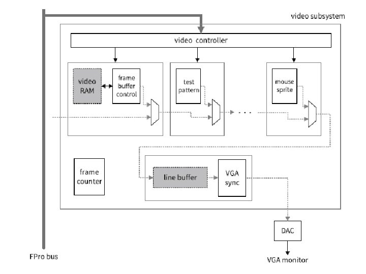
Slot Assignment of the Daisy Video Subsystem ECE 448 – FPGA and ASIC Design with VHDL 64

FPro System Memory Map 22 -bit word space, 24 -bit byte space 0 x xxxx xmmm mmma aaaa 64 MMIO Cores, each with 25 -word address space 11 aaaa aaaa 1 Frame Buffer Core, with 220 -word address space 10 xxxv vvaa aaaa 8 Video Cores, each with 214 -word address space ECE 448 – FPGA and ASIC Design with VHDL 65
- Slides: 65