
ECE 434 a Advanced Digital Systems L 06

- Slides: 27
ECE 434 a Advanced Digital Systems L 06 Electrical and Computer Engineering University of Western Ontario
Outline • What we know – Combinational Networks – Sequential Networks: • Basic Building Blocks, Mealy Networks, Max Frequency, Setup & Hold Times • What we do not know – Design: Moore Machine – Synchronous Design 9/17/2020 2
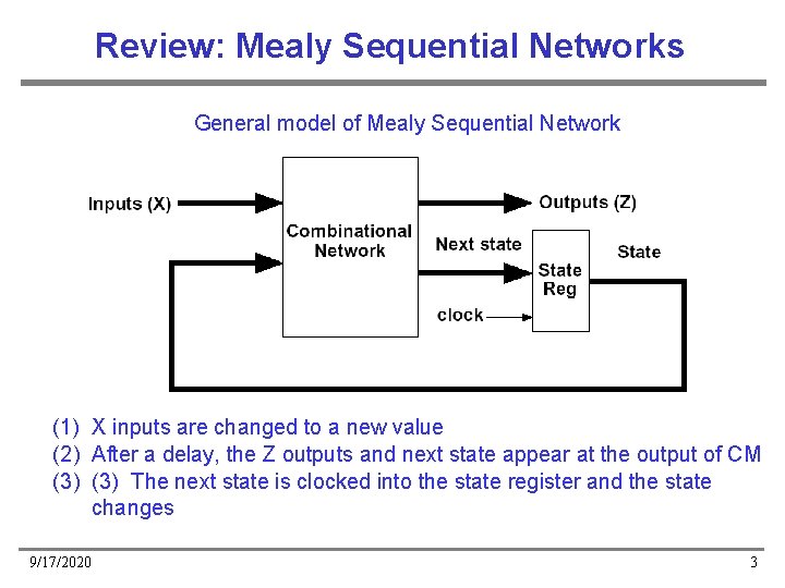
Review: Mealy Sequential Networks General model of Mealy Sequential Network (1) X inputs are changed to a new value (2) After a delay, the Z outputs and next state appear at the output of CM (3) The next state is clocked into the state register and the state changes 9/17/2020 3
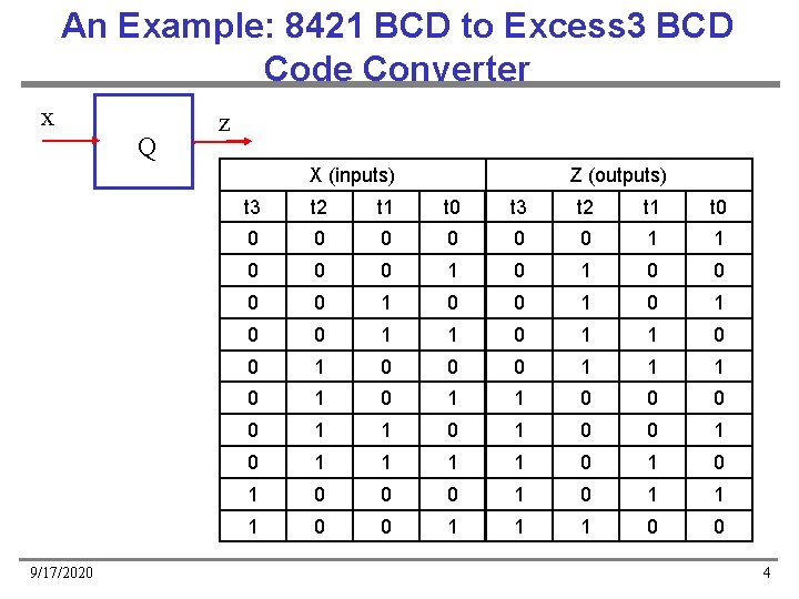
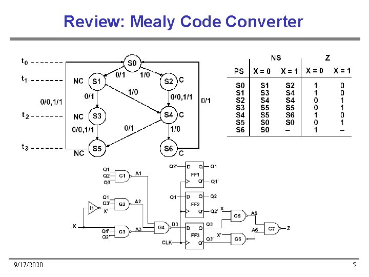
An Example: 8421 BCD to Excess 3 BCD Code Converter x Q z X (inputs) 9/17/2020 Z (outputs) t 3 t 2 t 1 t 0 0 0 0 1 1 0 0 0 1 0 0 1 1 0 0 0 1 1 1 0 0 1 1 0 0 1 1 1 1 0 1 0 0 0 1 1 1 0 0 4
Review: Mealy Code Converter 9/17/2020 5
State Assignment Rules 9/17/2020 6
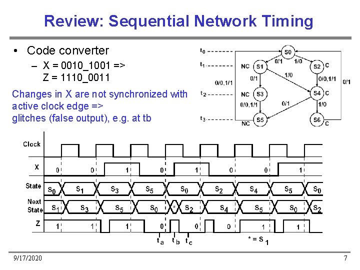
Review: Sequential Network Timing • Code converter – X = 0010_1001 => Z = 1110_0011 Changes in X are not synchronized with active clock edge => glitches (false output), e. g. at tb 9/17/2020 7
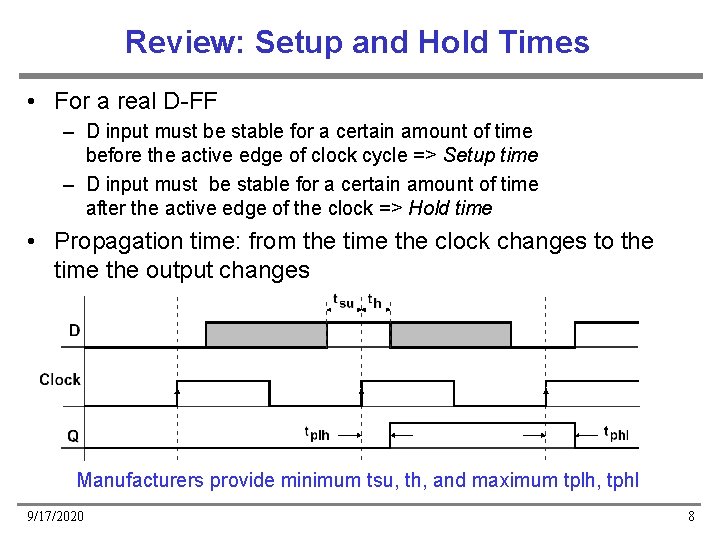
Review: Setup and Hold Times • For a real D-FF – D input must be stable for a certain amount of time before the active edge of clock cycle => Setup time – D input must be stable for a certain amount of time after the active edge of the clock => Hold time • Propagation time: from the time the clock changes to the time the output changes Manufacturers provide minimum tsu, th, and maximum tplh, tphl 9/17/2020 8
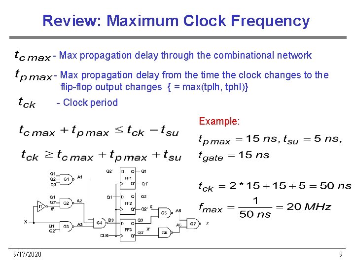
Review: Maximum Clock Frequency - Max propagation delay through the combinational network - Max propagation delay from the time the clock changes to the flip-flop output changes { = max(tplh, tphl)} - Clock period Example: 9/17/2020 9
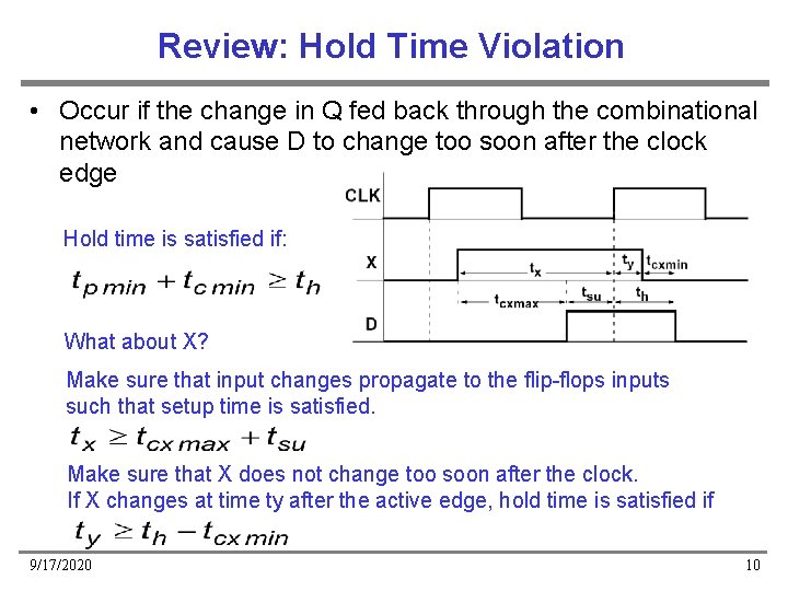
Review: Hold Time Violation • Occur if the change in Q fed back through the combinational network and cause D to change too soon after the clock edge Hold time is satisfied if: What about X? Make sure that input changes propagate to the flip-flops inputs such that setup time is satisfied. Make sure that X does not change too soon after the clock. If X changes at time ty after the active edge, hold time is satisfied if 9/17/2020 10
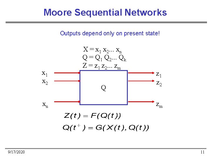
Moore Sequential Networks Outputs depend only on present state! x 1 x 2 xn 9/17/2020 X = x 1 x 2. . . xn Q = Q 1 Q 2. . . Qk Z = z 1 z 2. . . zm Q z 1 z 2 zm 11
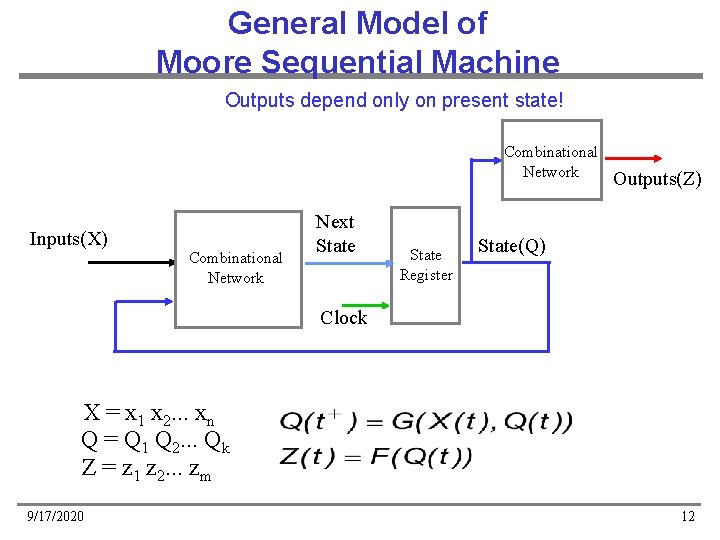
General Model of Moore Sequential Machine Outputs depend only on present state! Combinational Network Inputs(X) Combinational Network Next State Register Outputs(Z) State(Q) Clock X = x 1 x 2. . . xn Q = Q 1 Q 2. . . Qk Z = z 1 z 2. . . zm 9/17/2020 12
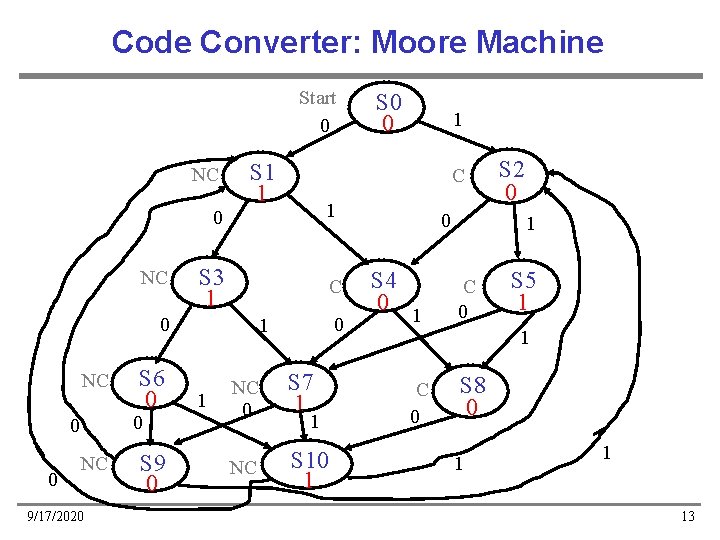
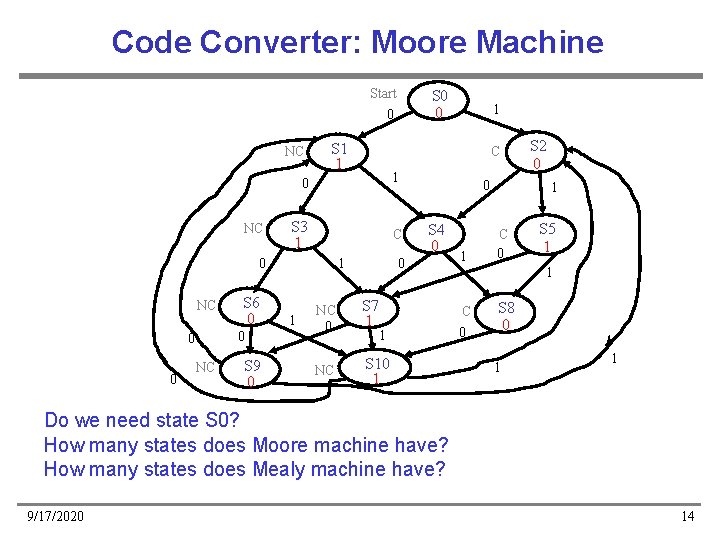
Code Converter: Moore Machine Start 0 NC NC S 1 1 NC 0 0 0 S 6 0 1 S 3 1 C NC 9/17/2020 S 9 0 0 1 1 1 C 0 0 S 0 0 NC 0 S 7 1 NC S 10 1 1 0 S 4 0 S 2 0 1 1 C 0 S 8 0 S 5 1 1 13
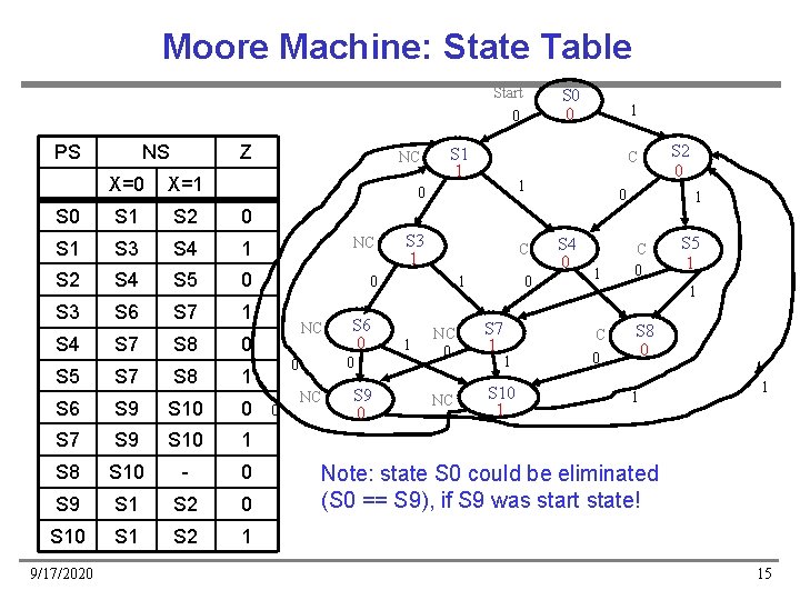
Code Converter: Moore Machine Start 0 NC NC S 1 1 0 0 0 S 6 0 1 S 3 1 C NC S 9 0 0 S 4 0 0 1 1 1 C 0 0 NC S 0 0 NC 0 S 7 1 NC S 10 1 1 1 S 2 0 1 C 0 S 5 1 1 C 0 S 8 0 1 1 Do we need state S 0? How many states does Moore machine have? How many states does Mealy machine have? 9/17/2020 14
Moore Machine: State Table Start 0 PS NS Z NC X=0 X=1 S 0 S 1 S 2 0 S 1 S 3 S 4 1 NC S 2 S 4 S 5 0 0 S 3 S 6 S 7 1 S 4 S 7 S 8 0 S 5 S 7 S 8 S 9 S 10 0 S 7 S 9 S 10 1 S 8 S 10 - 0 S 9 S 1 S 2 0 S 1 S 2 1 0 S 6 0 0 0 1 S 6 9/17/2020 NC NC S 9 0 S 1 1 S 0 0 C 0 1 S 3 1 C 0 1 1 1 NC 0 S 7 1 NC S 10 1 1 0 S 4 0 1 S 2 0 1 C 0 S 5 1 1 C 0 S 8 0 1 1 Note: state S 0 could be eliminated (S 0 == S 9), if S 9 was start state! 15
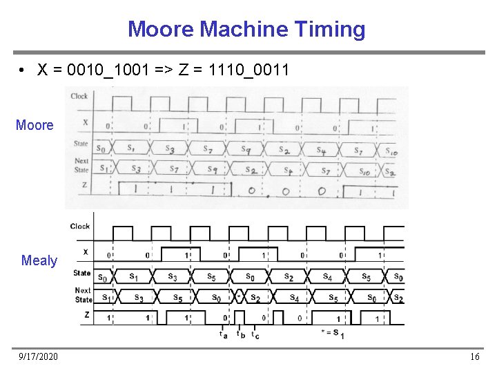
Moore Machine Timing • X = 0010_1001 => Z = 1110_0011 Moore Mealy 9/17/2020 16
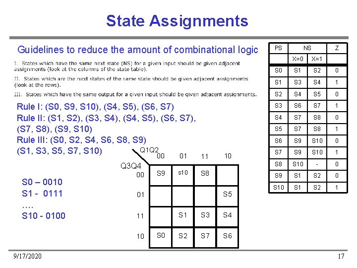
State Assignments Guidelines to reduce the amount of combinational logic Rule I: (S 0, S 9, S 10), (S 4, S 5), (S 6, S 7) Rule II: (S 1, S 2), (S 3, S 4), (S 4, S 5), (S 6, S 7), (S 7, S 8), (S 9, S 10) Rule III: (S 0, S 2, S 4, S 6, S 8, S 9) Q 1 Q 2 (S 1, S 3, S 5, S 7, S 10) 00 Q 3 Q 4 S 0 – 0010 S 1 - 0111 …. S 10 - 0100 00 s 10 11 10 S 8 S 5 01 11 10 9/17/2020 S 9 01 S 0 S 1 S 3 S 4 S 2 S 7 S 6 PS NS Z X=0 X=1 S 0 S 1 S 2 0 S 1 S 3 S 4 1 S 2 S 4 S 5 0 S 3 S 6 S 7 1 S 4 S 7 S 8 0 S 5 S 7 S 8 1 S 6 S 9 S 10 0 S 7 S 9 S 10 1 S 8 S 10 - 0 S 9 S 1 S 2 0 S 1 S 2 1 17
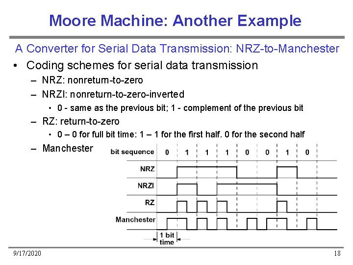
Moore Machine: Another Example A Converter for Serial Data Transmission: NRZ-to-Manchester • Coding schemes for serial data transmission – NRZ: nonreturn-to-zero – NRZI: nonreturn-to-zero-inverted • 0 - same as the previous bit; 1 - complement of the previous bit – RZ: return-to-zero • 0 – 0 for full bit time; 1 – 1 for the first half, 0 for the second half – Manchester 9/17/2020 18
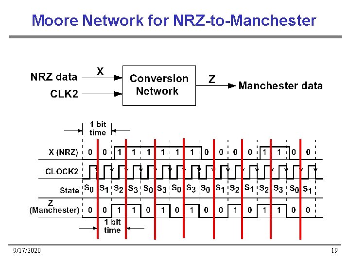
Moore Network for NRZ-to-Manchester 9/17/2020 19
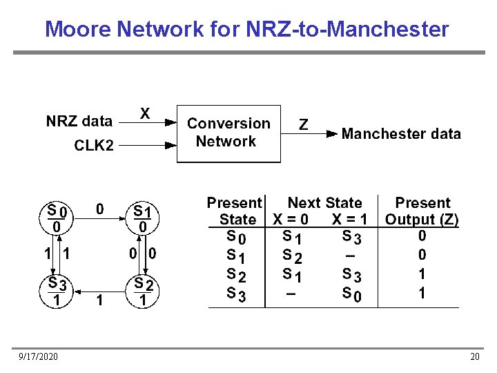
Moore Network for NRZ-to-Manchester 9/17/2020 20
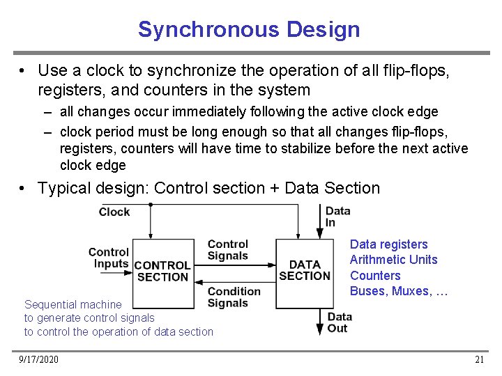
Synchronous Design • Use a clock to synchronize the operation of all flip-flops, registers, and counters in the system – all changes occur immediately following the active clock edge – clock period must be long enough so that all changes flip-flops, registers, counters will have time to stabilize before the next active clock edge • Typical design: Control section + Data Section Data registers Arithmetic Units Counters Buses, Muxes, … Sequential machine to generate control signals to control the operation of data section 9/17/2020 21
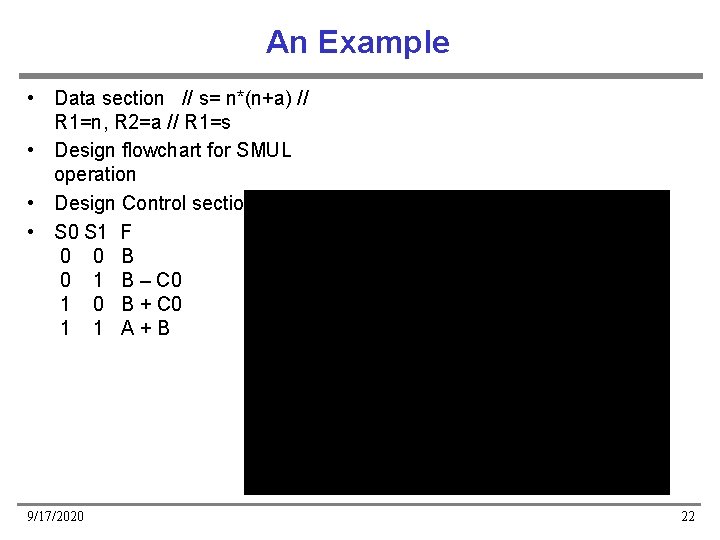
An Example • Data section // s= n*(n+a) // R 1=n, R 2=a // R 1=s • Design flowchart for SMUL operation • Design Control section • S 0 S 1 F 0 0 B 0 1 B – C 0 1 0 B + C 0 1 1 A+B 9/17/2020 22
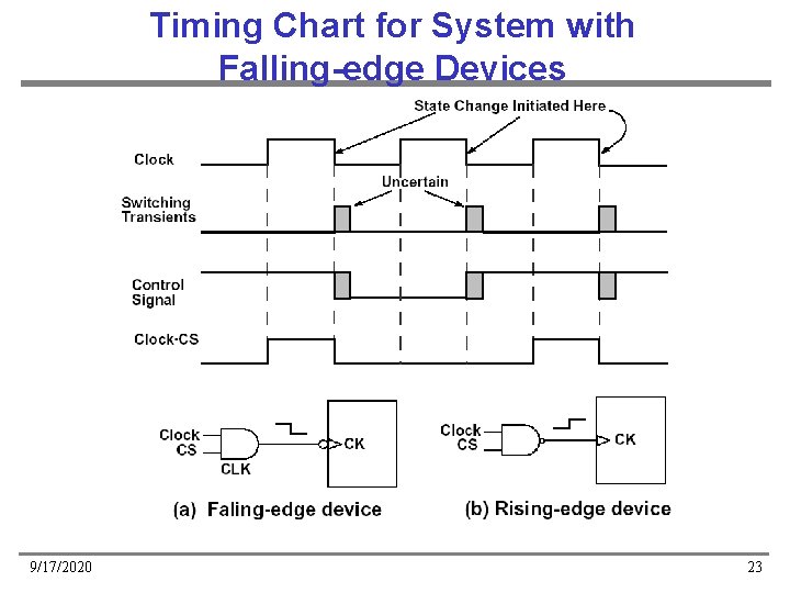
Timing Chart for System with Falling-edge Devices 9/17/2020 23
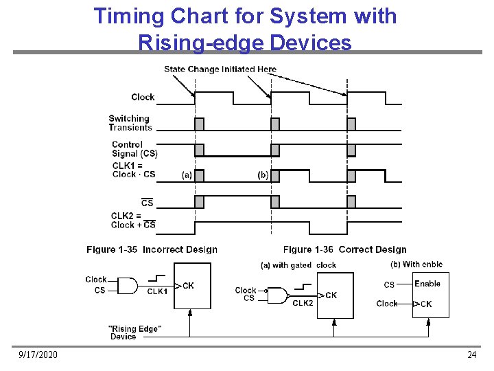
Timing Chart for System with Rising-edge Devices 9/17/2020 24
Principles of Synchronous Design • Method – All clock inputs to flip-flops, registers, counters, etc. , are driven directly from the system clock or from the clock ANDed with a control signal • Result – All state changes occur immediately following the active edge of the clock signal • Advantage – All switching transients, switching noise, etc. , occur between the clock pulses and have no effect on system performance 9/17/2020 25
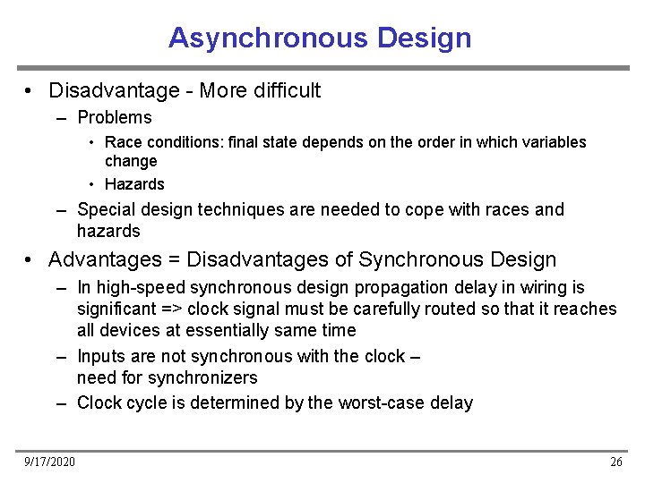
Asynchronous Design • Disadvantage - More difficult – Problems • Race conditions: final state depends on the order in which variables change • Hazards – Special design techniques are needed to cope with races and hazards • Advantages = Disadvantages of Synchronous Design – In high-speed synchronous design propagation delay in wiring is significant => clock signal must be carefully routed so that it reaches all devices at essentially same time – Inputs are not synchronous with the clock – need for synchronizers – Clock cycle is determined by the worst-case delay 9/17/2020 26
To Do • Read – Textbook chapters 1. 8, 1. 12 9/17/2020 27