ECE 3567 Lab 5 Serial Communications Dr Gregg

ECE 3567 Lab 5 Serial Communications Dr. Gregg J Chapman Autumn 2019 1

A Brief History of Serial Communications “MODEM” 2

RS-232 STANDARD 3

FULL MODEM Cable 4
 SCI MODEM CABLE 5")
Serial Communications Interface (RS-232) SCI MODEM CABLE 5

NULL MODEM CABLE 6

UART - Universal Asynchronous Receiver Transmitter • That's what describes UART. No voltage level, so you can have it at 3. 3 V or 5 V, whichever your microcontroller uses. Note that the microcontrollers which want to communicate via UART have to agree on the transmission speed, the bit-rate, as they only have the start bits falling edge to synchronize. That's called asynchronous communication. • For long distance communication (That doesn't have to be hundreds of meters) the 5 V UART is not very reliable, that's why it's converted to a higher voltage, typically +12 V for a "0" and 12 V for a "1". The data format remains the same. Then you have RS-232 (which you actually should call EIA-232, but nobody does. ) • The timing dependency is one of the big drawbacks of UART 7

UART - Universal Asynchronous Receiver Transmitter • one of the most used serial protocols. Most controllers have a hardware UART on board. • It uses a single data line for transmitting and one for receiving data. • Most often 8 -bit data is transferred, as follows: 1 start bit (low level), 8 data bits and 1 stop bit (high level). • The low level start bit and high level stop bit mean that there's always a high to low transition to start the communication. 8
 • I 2")
I 2 C - Inter-Integrated Circuit ( pronounced "I squared C") • I 2 C uses only 2 wires, one for the clock (SCL) and one for the data (SDA). • That means that master and slave send data over the same wire, again controlled by the master who creates the clock signal. • I 2 C doesn't use separate Slave Selects to select a particular device, but has addressing. • The first byte sent by the master holds a 7 bit address and a read/write bit, indicating whether the next byte(s) will also come from the master or should come from the slave. • After each byte, the receiver must send a "0" to acknowledge the reception of the byte • If the master wants to write a byte, the same process repeats • If the master wants to receive data it only generates the clock pulses. • The slave has to take care that the next bit is ready when the clock pulse is given. ACK 9

Serial Peripheral Interface 10

Which Serial Protocol is Best? UART I 2 C SPI Complexity Simple Easy to chain many devices. Complex as device increases Speed Slowest Faster than UART Fastest 1. 5 Mbps 3. 4 Mbit/s 48 -100 Mbps 11

Project Set-up Create a new project for Lab 5, download all files from the website and copy them into the project. 12

Checkpoint #1 – Have your Main. c file checked and demonstrate that your downloaded code is functioning correctly by verifying that it runs in the temperature mode. 13

Adding UART Communications 14
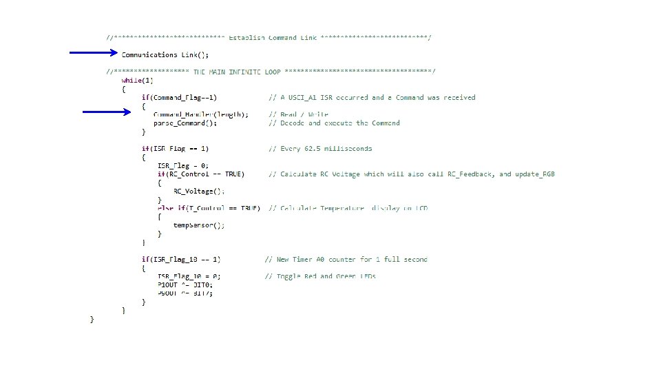

Changes to the Timer A 0 ISR It now runs every 62. 5 millisconds This means that 8 averages will take 0. 5 Seconds if you call RC_Voltage after the ISR_Flag = 1 in main() 17

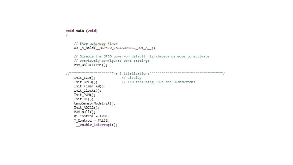
Initializes UART Communications on the MCU

• • • 9600 Baud 8 Data bits No Parity 1 Stop Bit No Hardware Handshaking

The Command Handler • • Data is in an array called val Most commands are 2 characters Setpoint commands for feedback are 5 characters Communications are interrupt driven Gets set in my. Uart_read. Buf

my. Uart. c

Building a Command 22

3567. h 23
![parse_Command void parse_Command() { if(val[0] == A) { if(val[1] == B ) Command =](http://slidetodoc.com/presentation_image_h2/47294f598ee631f84875f827e7704d89/image-24.jpg "parse_Command void parse_Command() { if(val[0] == A) { if(val[1] == B ) Command =")
parse_Command void parse_Command() { if(val[0] == A) { if(val[1] == B ) Command = AB; else if(val[1] == D) Command = AD; } else if(val[0] == B) { if(val[1] == E ) Command = BE; else if(val[1] == D) Command = BD; } else { Command = NULL; my. Uart_write. Buf( BACKCHANNEL_UART, "UNKNOWN COMMAND ", NULL, CRLF ); New_Data=0; my. Uart_write. Buf( BACKCHANNEL_UART, "", NULL, CRLF ); // Ask for the next Command } if(length >=5) // Included for Set. Point Command data { New_Data = 0; New_Data = (val[2]-48)*100 + (val[3]-48)*10 + (val[4]-48); length = 2; val[2]=0; val[3]=0; val[4]=0; } first character second character Command Unpack the data and convert to decimal numbers
 { case AB: break;")
Still in parse_Command /************************* Act on the Command *************************/ switch(Command) { case AB: break; case BD: break; case XX: break; default: break; } Command = NULL; my. Uart_write. Buf( BACKCHANNEL_UART, return; All actions for the Command go here } // Act on Command AB // Act on Command BD // etc. "Please enter the next Command Code: ", NULL, CRLF );

TE Command 1. 2. 3. 4. Enable T_Control and LCD_Control Disable RC_Control and LED_Control Turn off the LED Reset the Temperature and averages

TC Command 1. Change temp. Unit to Celsius 2. Reset the Temperature and averages TF Command 1. Change temp. Unit to Fahrenheit 2. Reset the Temperature and averages

RE Command 1. 2. 3. 4. Disable T_Control Enable RC_Control, LCD_Control and LED_Control Turn off the LED Set the TB 0 CCR 5 duty cycle to the initial value to give the RC voltage a value of 1. 65 volts, init_duty_cycle. 5. Reset the step size to max_step_size 6. Reset volts and the averager parameters

RS Command • Check to see if the RC_Control is TRUE, if it is. . . a. Multiply the New_Data value by 10 and transfer the result to RC_Set. Point b. IN LAB 6: Set the TB 0 CCR 5 duty cycle to init_duty_cycle. IN LAB 5: Set TB 0 CCR 5 equal to New_Data c. Set the step size max_step_size. d. Set the LED_Color to No_Color

Checkpoint #3 – Have TE, TC, TF, RE, and RS commands checked for completeness 30

Connecting the Serial Communications 31

You can use CMD and MODE to Identify available COM ports

You can also use the Terminal inside CCS: click choose one

When you run the project, the following messages will appear in the Terminal window:

Checkpoint #4 – Demonstrate the Terminal window messages 35

Checkpoint #5 – Demonstrate each Command TE, TC, TF, RE, and RS 36
- Slides: 36