ECE 255 Jan 23 2018 Lecture Instructor Weng


 Which of the following is not a full-wave rectifier?")
- Slides: 20
ECE 255 Jan 23, 2018 Lecture Instructor: Weng Cho Chew
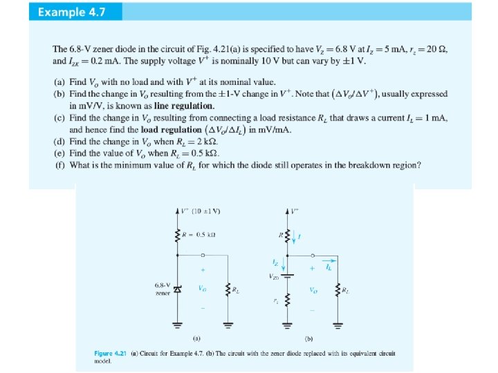
Zener Diodes • Voltage regulators, rectifiers, and clamping circuits. Symbol Internal voltage Linear circuit approximation around Q point.
Zener Diode As Shunt Regulator has a temperature coefficient in m. V/C
Diodes as Rectifiers Full wave rectifier
Half-Wave Rectifier • A constant voltage drop model for the diode. • PIV (peak inverse voltage)
Full-Wave Rectifier
Bridge Full-Wave Rectifier
Removing Current Ripple with Capacitor Ideal Capacitor Case: Capacitor holds charge forever Capacitor cannot discharge.
Non-Ideal Capacitor Case Capacitor cannot hold charge forever
A Smoothed Waveform A full wave rectifier case.
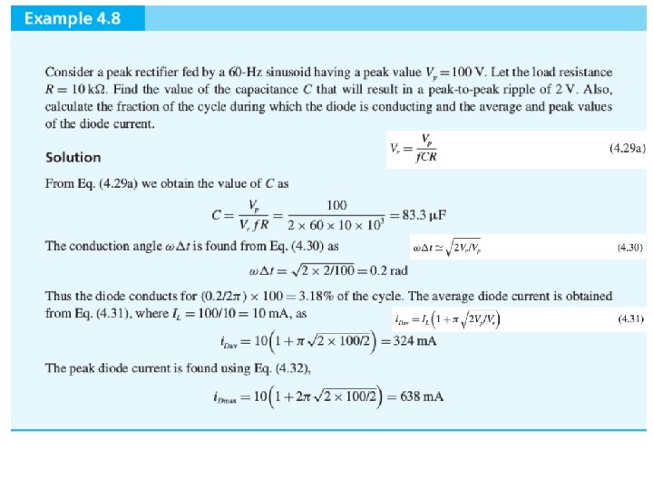
Math of Waveform Smoothing • Diode open circuit: Assuming that: Ripple Voltage Diode off
Math of Waveform Smoothing, Contd. • Diode conducting: Diode on interval Diode current during conduction interval : From KCL: Then average diode current:
Clamping and Limiter Circuit • An ideal voltage clamping circuit • A non ideal voltage clamping circuit
The Application of an Ideal Clamping Circuit
Designs of Clamping Circuits
Clicker Question 1 (1 Point) Which of the following is not a full-wave rectifier? (A) A transformer with a center tap (B) A diode connected to a capacitor (C) Bridge circuit