
ECE 232 Hardware Organization and Design Lecture 24

- Slides: 41
ECE 232 Hardware Organization and Design Lecture 24 Memory Technology and Organization Maciej Ciesielski www. ecs. umass. edu/ece/labs/vlsicad/ece 232/spr 2002/index_232. html ECE 232 L 24. Memory. 1 Adapted from Patterson 97 ©UCB Copyright 1998 Morgan Kaufmann Publishers
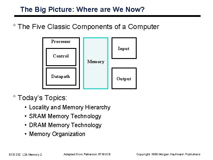
The Big Picture: Where are We Now? ° The Five Classic Components of a Computer Processor Input Control Memory Datapath Output ° Today’s Topics: • • Locality and Memory Hierarchy SRAM Memory Technology DRAM Memory Technology Memory Organization ECE 232 L 24. Memory. 2 Adapted from Patterson 97 ©UCB Copyright 1998 Morgan Kaufmann Publishers
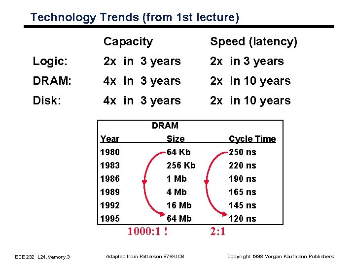
Technology Trends (from 1 st lecture) Capacity Speed (latency) Logic: 2 x in 3 years DRAM: 4 x in 3 years 2 x in 10 years Disk: 4 x in 3 years 2 x in 10 years DRAM Year 1980 1983 1986 Size 64 Kb 256 Kb 1 Mb Cycle Time 250 ns 220 ns 1989 1992 1995 4 Mb 16 Mb 64 Mb 165 ns 145 ns 120 ns 1000: 1 ! ECE 232 L 24. Memory. 3 Adapted from Patterson 97 ©UCB 2: 1 Copyright 1998 Morgan Kaufmann Publishers
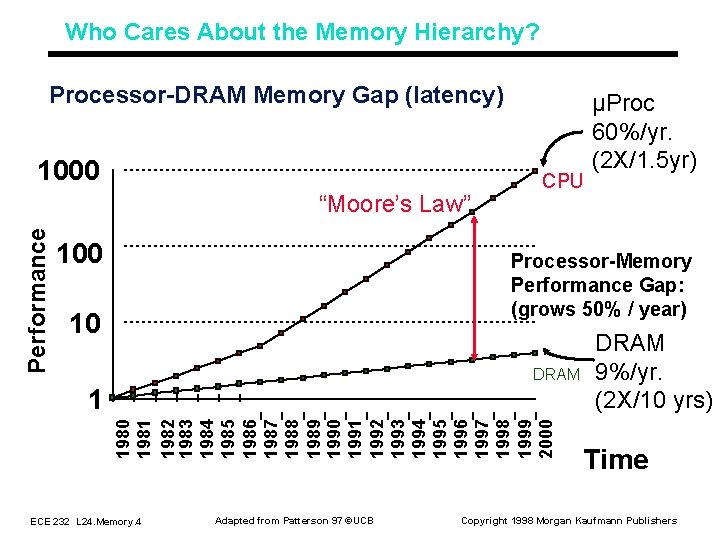
Who Cares About the Memory Hierarchy? Processor DRAM Memory Gap (latency) 1000 Performance “Moore’s Law” 100 CPU µProc 60%/yr. (2 X/1. 5 yr) Processor Memory Performance Gap: (grows 50% / year) 10 DRAM 1980 1981 1982 1983 1984 1985 1986 1987 1988 1989 1990 1991 1992 1993 1994 1995 1996 1997 1998 1999 2000 1 ECE 232 L 24. Memory. 4 Adapted from Patterson 97 ©UCB DRAM 9%/yr. (2 X/10 yrs) Time Copyright 1998 Morgan Kaufmann Publishers
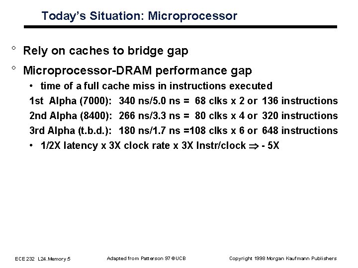
Today’s Situation: Microprocessor ° Rely on caches to bridge gap ° Microprocessor DRAM performance gap • time of a full cache miss in instructions executed 1 st Alpha (7000): 340 ns/5. 0 ns = 68 clks x 2 or 136 instructions 2 nd Alpha (8400): 266 ns/3. 3 ns = 80 clks x 4 or 320 instructions 3 rd Alpha (t. b. d. ): 180 ns/1. 7 ns =108 clks x 6 or 648 instructions • 1/2 X latency x 3 X clock rate x 3 X Instr/clock Þ 5 X ECE 232 L 24. Memory. 5 Adapted from Patterson 97 ©UCB Copyright 1998 Morgan Kaufmann Publishers
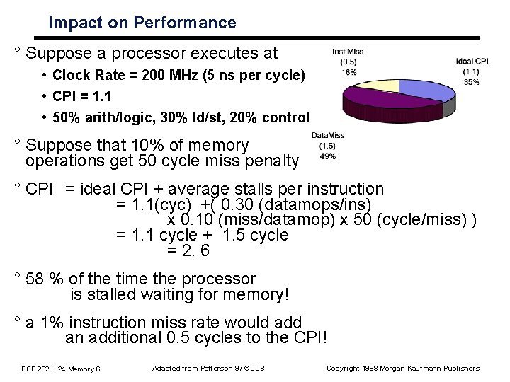
Impact on Performance ° Suppose a processor executes at • Clock Rate = 200 MHz (5 ns per cycle) • CPI = 1. 1 • 50% arith/logic, 30% ld/st, 20% control ° Suppose that 10% of memory operations get 50 cycle miss penalty ° CPI = ideal CPI + average stalls per instruction = 1. 1(cyc) +( 0. 30 (datamops/ins) x 0. 10 (miss/datamop) x 50 (cycle/miss) ) = 1. 1 cycle + 1. 5 cycle = 2. 6 ° 58 % of the time the processor is stalled waiting for memory! ° a 1% instruction miss rate would add an additional 0. 5 cycles to the CPI! ECE 232 L 24. Memory. 6 Adapted from Patterson 97 ©UCB Copyright 1998 Morgan Kaufmann Publishers
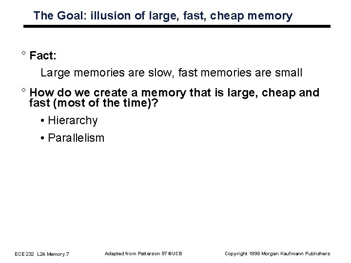
The Goal: illusion of large, fast, cheap memory ° Fact: Large memories are slow, fast memories are small ° How do we create a memory that is large, cheap and fast (most of the time)? • Hierarchy • Parallelism ECE 232 L 24. Memory. 7 Adapted from Patterson 97 ©UCB Copyright 1998 Morgan Kaufmann Publishers
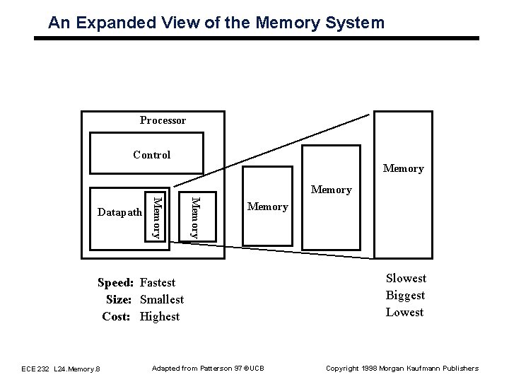
An Expanded View of the Memory System Processor Control Memory Datapath Memory Speed: Fastest Size: Smallest Cost: Highest ECE 232 L 24. Memory. 8 Adapted from Patterson 97 ©UCB Slowest Biggest Lowest Copyright 1998 Morgan Kaufmann Publishers
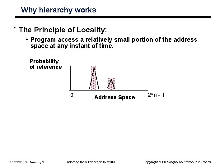
Why hierarchy works ° The Principle of Locality: • Program access a relatively small portion of the address space at any instant of time. Probability of reference 0 ECE 232 L 24. Memory. 9 Address Space Adapted from Patterson 97 ©UCB 2^n - 1 Copyright 1998 Morgan Kaufmann Publishers
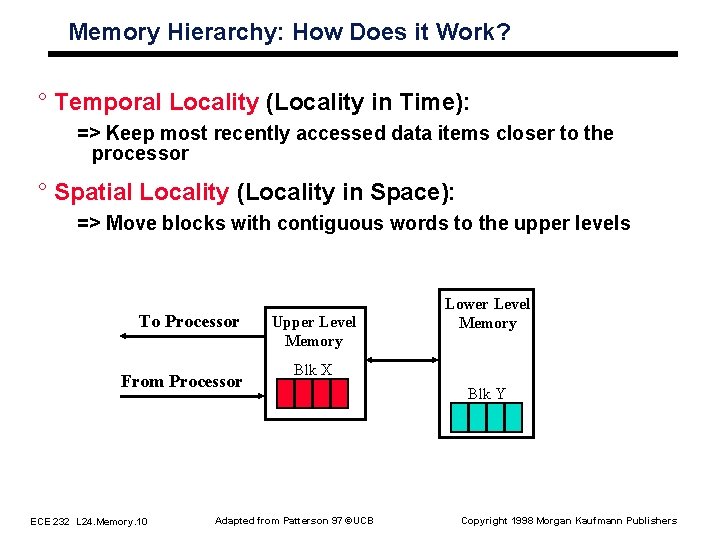
Memory Hierarchy: How Does it Work? ° Temporal Locality (Locality in Time): => Keep most recently accessed data items closer to the processor ° Spatial Locality (Locality in Space): => Move blocks with contiguous words to the upper levels To Processor From Processor ECE 232 L 24. Memory. 10 Upper Level Memory Lower Level Memory Blk X Adapted from Patterson 97 ©UCB Blk Y Copyright 1998 Morgan Kaufmann Publishers
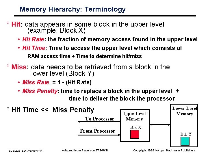
Memory Hierarchy: Terminology ° Hit: data appears in some block in the upper level (example: Block X) • Hit Rate: the fraction of memory access found in the upper level • Hit Time: Time to access the upper level which consists of RAM access time + Time to determine hit/miss ° Miss: data needs to be retrieved from a block in the lower level (Block Y) • Miss Rate = 1 (Hit Rate) • Miss Penalty: time to replace a block in the upper level + time to deliver the block the processor ° Hit Time << Miss Penalty To Processor From Processor ECE 232 L 24. Memory. 11 Adapted from Patterson 97 ©UCB Upper Level Memory Lower Level Memory Blk X Blk Y Copyright 1998 Morgan Kaufmann Publishers
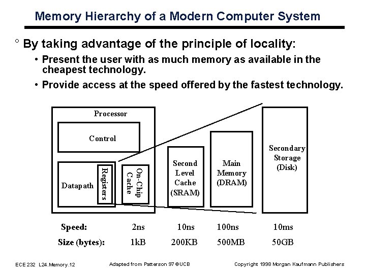
Memory Hierarchy of a Modern Computer System ° By taking advantage of the principle of locality: • Present the user with as much memory as available in the cheapest technology. • Provide access at the speed offered by the fastest technology. Processor Control Speed: Size (bytes): ECE 232 L 24. Memory. 12 On-Chip Cache Registers Datapath Second Level Cache (SRAM) 2 ns 10 ns 1 k. B 200 KB Adapted from Patterson 97 ©UCB Main Memory (DRAM) Secondary Storage (Disk) 100 ns 10 ms 500 MB 50 GB Copyright 1998 Morgan Kaufmann Publishers
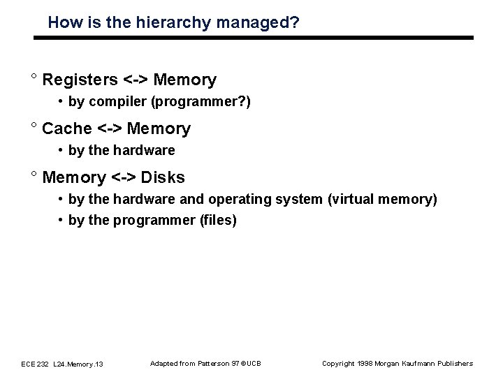
How is the hierarchy managed? ° Registers < > Memory • by compiler (programmer? ) ° Cache < > Memory • by the hardware ° Memory < > Disks • by the hardware and operating system (virtual memory) • by the programmer (files) ECE 232 L 24. Memory. 13 Adapted from Patterson 97 ©UCB Copyright 1998 Morgan Kaufmann Publishers
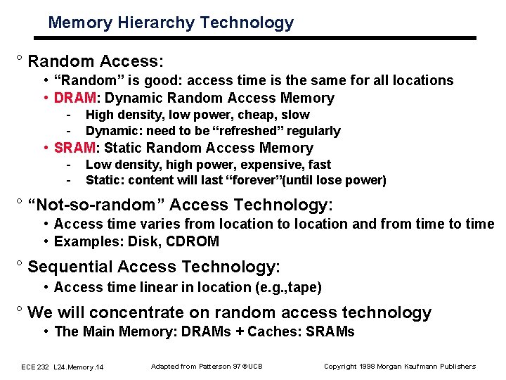
Memory Hierarchy Technology ° Random Access: • “Random” is good: access time is the same for all locations • DRAM: Dynamic Random Access Memory - High density, low power, cheap, slow Dynamic: need to be “refreshed” regularly • SRAM: Static Random Access Memory - Low density, high power, expensive, fast Static: content will last “forever”(until lose power) ° “Not so random” Access Technology: • Access time varies from location to location and from time to time • Examples: Disk, CDROM ° Sequential Access Technology: • Access time linear in location (e. g. , tape) ° We will concentrate on random access technology • The Main Memory: DRAMs + Caches: SRAMs ECE 232 L 24. Memory. 14 Adapted from Patterson 97 ©UCB Copyright 1998 Morgan Kaufmann Publishers
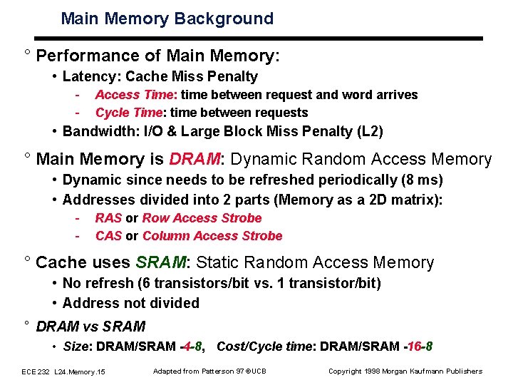
Main Memory Background ° Performance of Main Memory: • Latency: Cache Miss Penalty - Access Time: time between request and word arrives Cycle Time: time between requests • Bandwidth: I/O & Large Block Miss Penalty (L 2) ° Main Memory is DRAM: Dynamic Random Access Memory • Dynamic since needs to be refreshed periodically (8 ms) • Addresses divided into 2 parts (Memory as a 2 D matrix): - RAS or Row Access Strobe CAS or Column Access Strobe ° Cache uses SRAM: Static Random Access Memory • No refresh (6 transistors/bit vs. 1 transistor/bit) • Address not divided ° DRAM vs SRAM • Size: DRAM/SRAM 4 -8, Cost/Cycle time: DRAM/SRAM 16 -8 ECE 232 L 24. Memory. 15 Adapted from Patterson 97 ©UCB Copyright 1998 Morgan Kaufmann Publishers
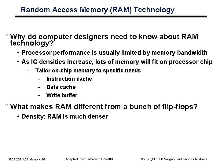
Random Access Memory (RAM) Technology ° Why do computer designers need to know about RAM technology? • Processor performance is usually limited by memory bandwidth • As IC densities increase, lots of memory will fit on processor chip - Tailor on chip memory to specific needs - Instruction cache - Data cache - Write buffer ° What makes RAM different from a bunch of flip flops? • Density: RAM is much denser ECE 232 L 24. Memory. 16 Adapted from Patterson 97 ©UCB Copyright 1998 Morgan Kaufmann Publishers
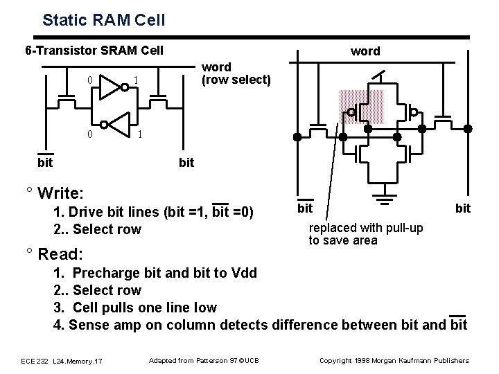
Static RAM Cell 6 Transistor SRAM Cell 0 0 bit word (row select) 1 1 bit ° Write: 1. Drive bit lines (bit =1, bit =0) 2. . Select row ° Read: bit replaced with pull-up to save area 1. Precharge bit and bit to Vdd 2. . Select row 3. Cell pulls one line low 4. Sense amp on column detects difference between bit and bit ECE 232 L 24. Memory. 17 Adapted from Patterson 97 ©UCB Copyright 1998 Morgan Kaufmann Publishers
Typical SRAM Organization: 16 word x 4 bit Din 3 Din 2 Din 1 Din 0 Wr. En Precharge Wr Driver & - Precharger + SRAM Cell Word 0 Word 1 SRAM Cell : : SRAM Cell - Sense Amp + Dout 3 Dout 2 Dout 1 Dout 0 ECE 232 L 24. Memory. 18 Adapted from Patterson 97 ©UCB Address Decoder SRAM Cell Wr Driver & - Precharger + A 0 A 1 A 2 A 3 Word 15 Q: Which is longer: word line or bit line? Copyright 1998 Morgan Kaufmann Publishers
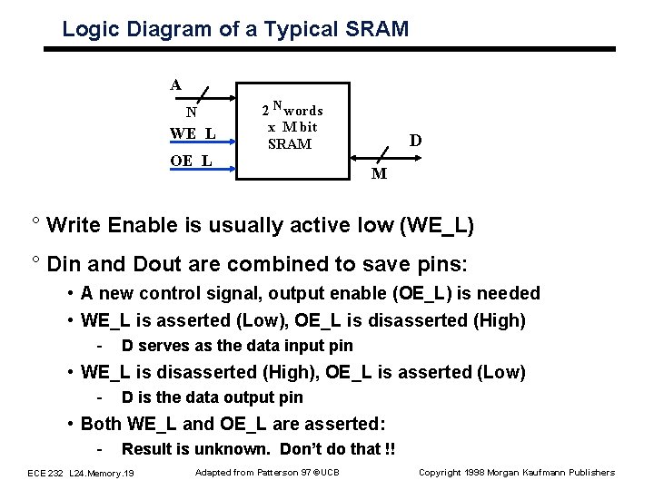
Logic Diagram of a Typical SRAM A N WE_L OE_L 2 N words x M bit SRAM D M ° Write Enable is usually active low (WE_L) ° Din and Dout are combined to save pins: • A new control signal, output enable (OE_L) is needed • WE_L is asserted (Low), OE_L is disasserted (High) - D serves as the data input pin • WE_L is disasserted (High), OE_L is asserted (Low) - D is the data output pin • Both WE_L and OE_L are asserted: - Result is unknown. Don’t do that !! ECE 232 L 24. Memory. 19 Adapted from Patterson 97 ©UCB Copyright 1998 Morgan Kaufmann Publishers
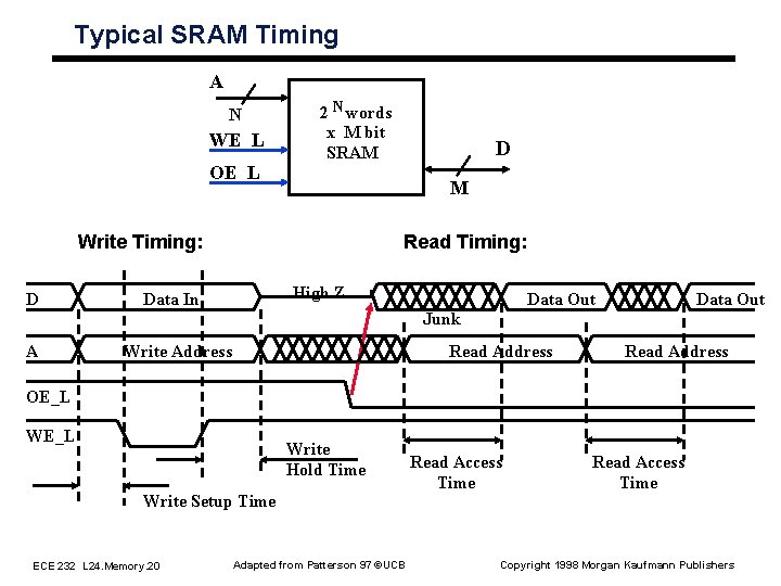
Typical SRAM Timing A N WE_L OE_L 2 N words x M bit SRAM M Write Timing: D D Read Timing: High Z Data In Data Out Junk A Write Address Read Address OE_L Write Hold Time Write Setup Time ECE 232 L 24. Memory. 20 Adapted from Patterson 97 ©UCB Read Access Time Copyright 1998 Morgan Kaufmann Publishers
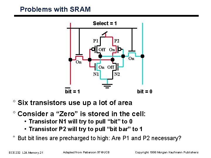
Problems with SRAM Select = 1 P 2 Off On On Off N 1 N 2 bit = 1 bit = 0 ° Six transistors use up a lot of area ° Consider a “Zero” is stored in the cell: • Transistor N 1 will try to pull “bit” to 0 • Transistor P 2 will try to pull “bit bar” to 1 ° But bit lines are precharged to high: Are P 1 and P 2 necessary? ECE 232 L 24. Memory. 21 Adapted from Patterson 97 ©UCB Copyright 1998 Morgan Kaufmann Publishers
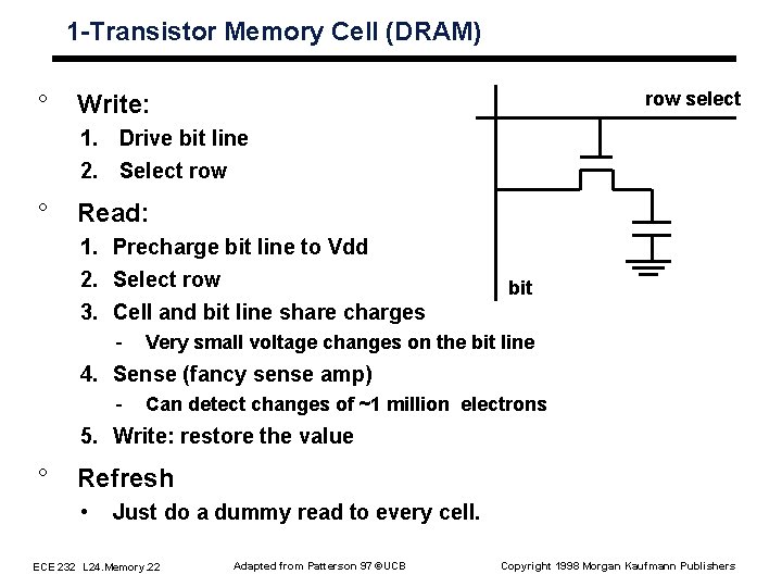
1 Transistor Memory Cell (DRAM) ° row select Write: 1. Drive bit line 2. Select row ° Read: 1. Precharge bit line to Vdd 2. Select row 3. Cell and bit line share charges - bit Very small voltage changes on the bit line 4. Sense (fancy sense amp) - Can detect changes of ~1 million electrons 5. Write: restore the value ° Refresh • Just do a dummy read to every cell. ECE 232 L 24. Memory. 22 Adapted from Patterson 97 ©UCB Copyright 1998 Morgan Kaufmann Publishers
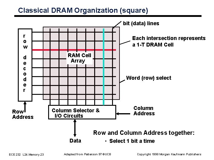
Classical DRAM Organization (square) bit (data) lines r o w d e c o d e r Row Address Each intersection represents a 1 T DRAM Cell Array Word (row) select Column Address Column Selector & I/O Circuits Row and Column Address together: Data ECE 232 L 24. Memory. 23 • Select 1 bit a time Adapted from Patterson 97 ©UCB Copyright 1998 Morgan Kaufmann Publishers
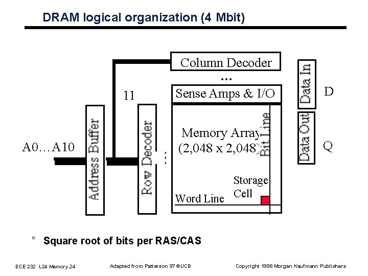
DRAM logical organization (4 Mbit) 11 A 0…A 10 Column Decoder … Sense Amps & I/O D Memory Array (2, 048 x 2, 048) Q Storage Word Line Cell ° Square root of bits per RAS/CAS ECE 232 L 24. Memory. 24 Adapted from Patterson 97 ©UCB Copyright 1998 Morgan Kaufmann Publishers
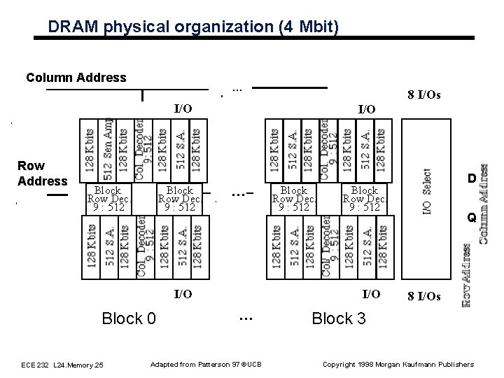
DRAM physical organization (4 Mbit) Column Address … 8 I/Os I/O Row Address Block Row Dec. 9 : 512 I/O … I/O Block 0 ECE 232 L 24. Memory. 25 Block Row Dec. 9 : 512 I/O … Adapted from Patterson 97 ©UCB D Q 8 I/Os Block 3 Copyright 1998 Morgan Kaufmann Publishers
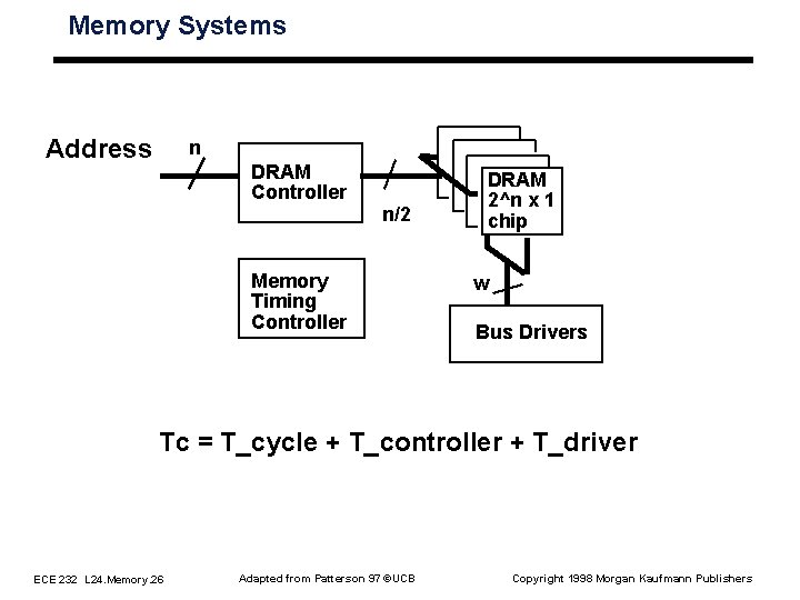
Memory Systems Address n DRAM Controller n/2 Memory Timing Controller DRAM 2^n x 1 chip w Bus Drivers Tc = T_cycle + T_controller + T_driver ECE 232 L 24. Memory. 26 Adapted from Patterson 97 ©UCB Copyright 1998 Morgan Kaufmann Publishers
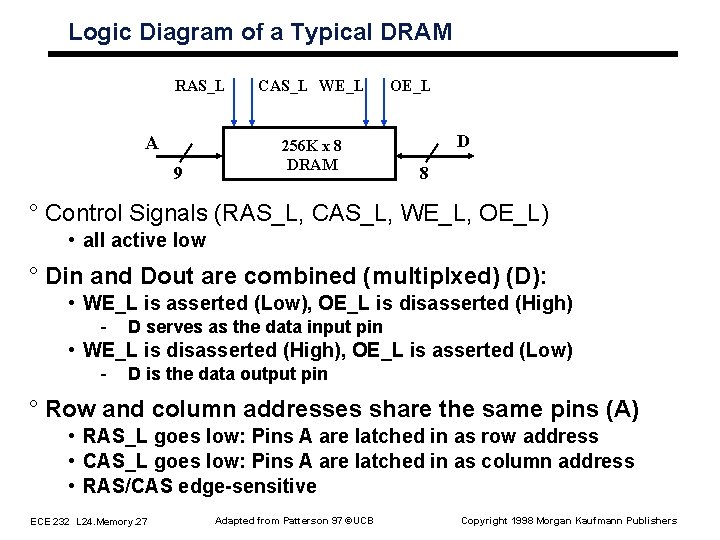
Logic Diagram of a Typical DRAM RAS_L A 9 CAS_L WE_L 256 K x 8 DRAM OE_L D 8 ° Control Signals (RAS_L, CAS_L, WE_L, OE_L) • all active low ° Din and Dout are combined (multiplxed) (D): • WE_L is asserted (Low), OE_L is disasserted (High) - D serves as the data input pin • WE_L is disasserted (High), OE_L is asserted (Low) - D is the data output pin ° Row and column addresses share the same pins (A) • RAS_L goes low: Pins A are latched in as row address • CAS_L goes low: Pins A are latched in as column address • RAS/CAS edge sensitive ECE 232 L 24. Memory. 27 Adapted from Patterson 97 ©UCB Copyright 1998 Morgan Kaufmann Publishers
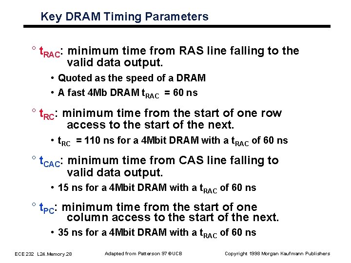
Key DRAM Timing Parameters ° t. RAC: minimum time from RAS line falling to the valid data output. • Quoted as the speed of a DRAM • A fast 4 Mb DRAM t. RAC = 60 ns ° t. RC: minimum time from the start of one row access to the start of the next. • t. RC = 110 ns for a 4 Mbit DRAM with a t. RAC of 60 ns ° t. CAC: minimum time from CAS line falling to valid data output. • 15 ns for a 4 Mbit DRAM with a t. RAC of 60 ns ° t. PC: minimum time from the start of one column access to the start of the next. • 35 ns for a 4 Mbit DRAM with a t. RAC of 60 ns ECE 232 L 24. Memory. 28 Adapted from Patterson 97 ©UCB Copyright 1998 Morgan Kaufmann Publishers
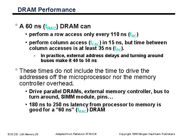
DRAM Performance ° A 60 ns (t. RAC) DRAM can • perform a row access only every 110 ns (t. RC) • perform column access (t. CAC) in 15 ns, but time between column accesses is at least 35 ns (t. PC). - In practice, external address delays and turning around buses make it 40 to 50 ns ° These times do not include the time to drive the addresses off the microprocessor nor the memory controller overhead. • Drive parallel DRAMs, external memory controller, bus to turn around, SIMM module, pins… • 180 ns to 250 ns latency from processor to memory is good for a “ 60 ns” (t. RAC) DRAM ECE 232 L 24. Memory. 29 Adapted from Patterson 97 ©UCB Copyright 1998 Morgan Kaufmann Publishers
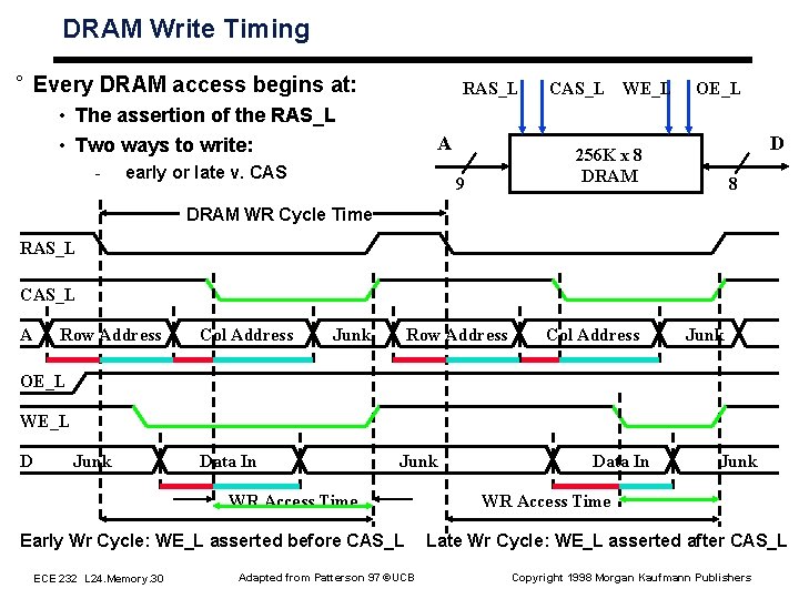
DRAM Write Timing ° Every DRAM access begins at: RAS_L • The assertion of the RAS_L • Two ways to write: - A early or late v. CAS_L WE_L OE_L D 256 K x 8 DRAM 9 8 DRAM WR Cycle Time RAS_L CAS_L A Row Address Col Address Junk OE_L WE_L D Junk Data In Junk WR Access Time Early Wr Cycle: WE_L asserted before CAS_L ECE 232 L 24. Memory. 30 Adapted from Patterson 97 ©UCB Data In Junk WR Access Time Late Wr Cycle: WE_L asserted after CAS_L Copyright 1998 Morgan Kaufmann Publishers
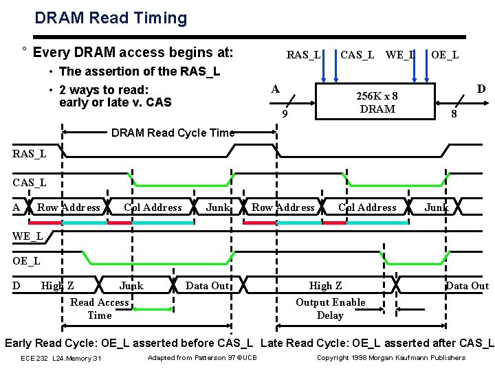
DRAM Read Timing ° Every DRAM access begins at: RAS_L • The assertion of the RAS_L • 2 ways to read: early or late v. CAS A CAS_L WE_L OE_L D 256 K x 8 DRAM 9 8 DRAM Read Cycle Time RAS_L CAS_L A Row Address Col Address Junk WE_L OE_L D High Z Junk Read Access Time Data Out High Z Output Enable Delay Data Out Early Read Cycle: OE_L asserted before CAS_L Late Read Cycle: OE_L asserted after CAS_L ECE 232 L 24. Memory. 31 Adapted from Patterson 97 ©UCB Copyright 1998 Morgan Kaufmann Publishers
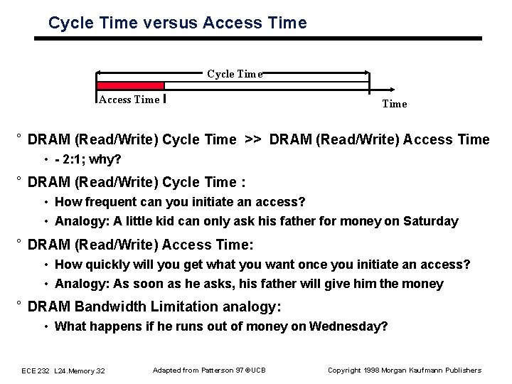
Cycle Time versus Access Time Cycle Time Access Time ° DRAM (Read/Write) Cycle Time >> DRAM (Read/Write) Access Time • 2: 1; why? ° DRAM (Read/Write) Cycle Time : • How frequent can you initiate an access? • Analogy: A little kid can only ask his father for money on Saturday ° DRAM (Read/Write) Access Time: • How quickly will you get what you want once you initiate an access? • Analogy: As soon as he asks, his father will give him the money ° DRAM Bandwidth Limitation analogy: • What happens if he runs out of money on Wednesday? ECE 232 L 24. Memory. 32 Adapted from Patterson 97 ©UCB Copyright 1998 Morgan Kaufmann Publishers
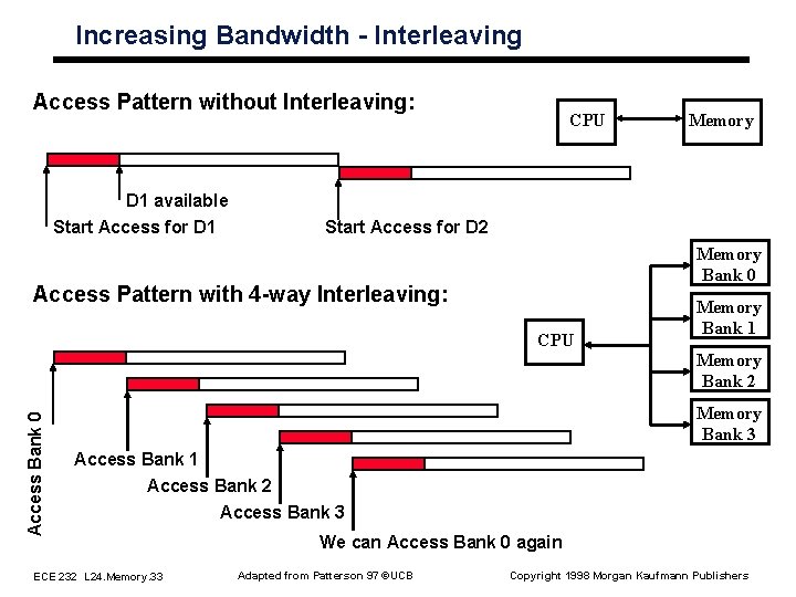
Increasing Bandwidth Interleaving Access Pattern without Interleaving: D 1 available Start Access for D 1 CPU Memory Start Access for D 2 Memory Bank 0 Access Pattern with 4 way Interleaving: CPU Memory Bank 1 Access Bank 0 Memory Bank 2 Memory Bank 3 Access Bank 1 Access Bank 2 Access Bank 3 ECE 232 L 24. Memory. 33 We can Access Bank 0 again Adapted from Patterson 97 ©UCB Copyright 1998 Morgan Kaufmann Publishers
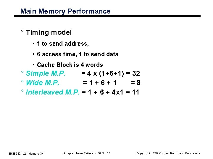
Main Memory Performance ° Timing model • 1 to send address, • 6 access time, 1 to send data • Cache Block is 4 words ° Simple M. P. = 4 x (1+6+1) = 32 ° Wide M. P. = 1 + 6 + 1 = 8 ° Interleaved M. P. = 1 + 6 + 4 x 1 = 11 ECE 232 L 24. Memory. 34 Adapted from Patterson 97 ©UCB Copyright 1998 Morgan Kaufmann Publishers
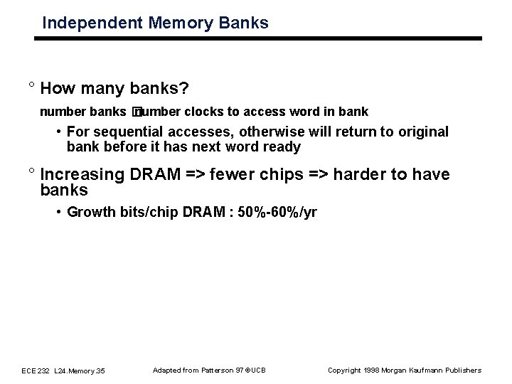
Independent Memory Banks ° How many banks? number banks � number clocks to access word in bank • For sequential accesses, otherwise will return to original bank before it has next word ready ° Increasing DRAM => fewer chips => harder to have banks • Growth bits/chip DRAM : 50% 60%/yr ECE 232 L 24. Memory. 35 Adapted from Patterson 97 ©UCB Copyright 1998 Morgan Kaufmann Publishers
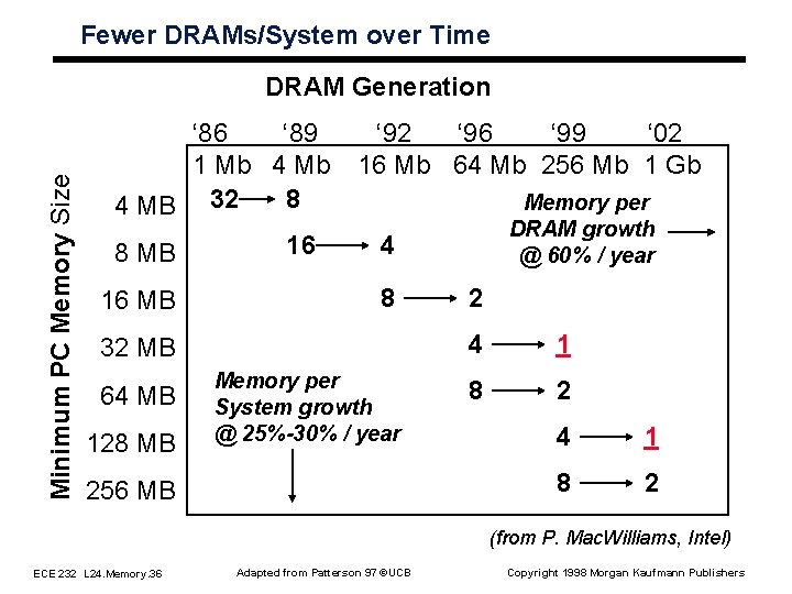
Fewer DRAMs/System over Time Minimum PC Memory Size DRAM Generation ‘ 86 ‘ 89 1 Mb 4 Mb 8 4 MB 32 16 8 MB 16 MB ‘ 92 ‘ 96 ‘ 99 ‘ 02 16 Mb 64 Mb 256 Mb 1 Gb 4 8 32 MB 64 MB 128 MB Memory per DRAM growth @ 60% / year Memory per System growth @ 25%-30% / year 256 MB 2 4 1 8 2 (from P. Mac. Williams, Intel) ECE 232 L 24. Memory. 36 Adapted from Patterson 97 ©UCB Copyright 1998 Morgan Kaufmann Publishers
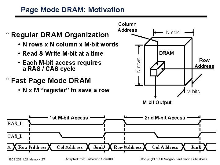
Page Mode DRAM: Motivation Column Address • N rows x N column x M bit words • Read & Write M bit at a time • Each M bit access requires a RAS / CAS cycle N cols DRAM Row Address N rows ° Regular DRAM Organization ° Fast Page Mode DRAM • N x M “register” to save a row M bits M bit Output 1 st M bit Access 2 nd M bit Access RAS_L CAS_L A Row Address ECE 232 L 24. Memory. 37 Col Address Junk Row Address Adapted from Patterson 97 ©UCB Col Address Junk Copyright 1998 Morgan Kaufmann Publishers
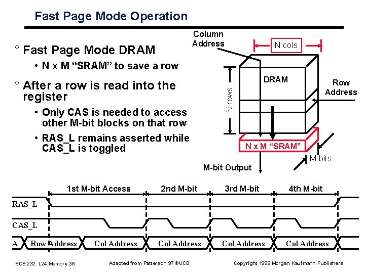
Fast Page Mode Operation Column Address ° Fast Page Mode DRAM N cols • N x M “SRAM” to save a row • Only CAS is needed to access other M bit blocks on that row • RAS_L remains asserted while CAS_L is toggled Row Address N rows ° After a row is read into the register DRAM N x M “SRAM” M bits M bit Output 1 st M bit Access 2 nd M bit 3 rd M bit 4 th M bit Col Address RAS_L CAS_L A Row Address ECE 232 L 24. Memory. 38 Col Address Adapted from Patterson 97 ©UCB Copyright 1998 Morgan Kaufmann Publishers
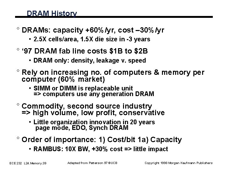
DRAM History ° DRAMs: capacity +60%/yr, cost – 30%/yr • 2. 5 X cells/area, 1. 5 X die size in 3 years ° ‘ 97 DRAM fab line costs $1 B to $2 B • DRAM only: density, leakage v. speed ° Rely on increasing no. of computers & memory per computer (60% market) • SIMM or DIMM is replaceable unit => computers use any generation DRAM ° Commodity, second source industry => high volume, low profit, conservative • Little organization innovation in 20 years page mode, EDO, Synch DRAM ° Order of importance: 1) Cost/bit 1 a) Capacity • RAMBUS: 10 X BW, +30% cost => little impact ECE 232 L 24. Memory. 39 Adapted from Patterson 97 ©UCB Copyright 1998 Morgan Kaufmann Publishers
Today’s Situation: DRAM ° Commodity, second source industry Þ high volume, low profit, conservative • Little organization innovation (vs. processors) in 20 years: page mode, EDO, Synch DRAM ° DRAM industry at a crossroads: • Fewer DRAMs per computer over time - Growth bits/chip DRAM : 50% 60%/yr • Starting to question buying larger DRAMs? ECE 232 L 24. Memory. 40 Adapted from Patterson 97 ©UCB Copyright 1998 Morgan Kaufmann Publishers
Summary ° Two Different Types of Locality: • Temporal Locality (Locality in Time): If an item is referenced, it will tend to be referenced again soon. • Spatial Locality (Locality in Space): If an item is referenced, items whose addresses are close by tend to be referenced soon. ° Taking advantage of the principle of locality: • Present the user with as much memory as is available in the cheapest technology. • Provide access at the speed offered by the fastest technology. ° DRAM is slow but cheap and dense: • Good choice for presenting the user with a BIG memory system ° SRAM is fast but expensive and not very dense: • Good choice for providing the user FAST access time. ECE 232 L 24. Memory. 41 Adapted from Patterson 97 ©UCB Copyright 1998 Morgan Kaufmann Publishers