EAT 212 SOIL MECHANICS Chapter 4 SHEAR STRENGTH


")


 soil Failure envelopes of cohesion less soil")


 • Only slow drained tests are performed in this test.")


 • Depending on whether drainage is allowed or not during i)")
 Test (slow test) • Drainage valves OPEN during consolidation as well")


 Find the normal stress")


 Test • Apply σ3 and wait until the soil consolidates •")


 Test (quick test) • Pore pressure develops during shear. Pore pressure")


 • POINT B – Vertical : s = 57. 2 k. Pa")

- Slides: 64
EAT 212 SOIL MECHANICS Chapter 4: SHEAR STRENGTH OF SOIL PREPARED BY SHAMILAH ANUDAI@ANUAR
LESSON PLAN SHEAR STRENGTH CONSOLIDATION OF SOIL WEEK 11 WEEK 14 15/11 & 17/11 6/12 & 8/12 WEEK 15 22/11 & 24/11 13/12 & 15/12 WEEK 13 TEST 2 will be on 15/12 29/11 & 1/12
CONTENT Shear failure in soil Drained and Undrained condition Mohr-coulomb failure Shear strength of saturated sands and gravels Shear strength of saturated clays Shear strength evaluation
Strength of different materials Steel Tensile strength Concrete Soil Compressive strength Shear strength Complex behavior Presence of pore water 4
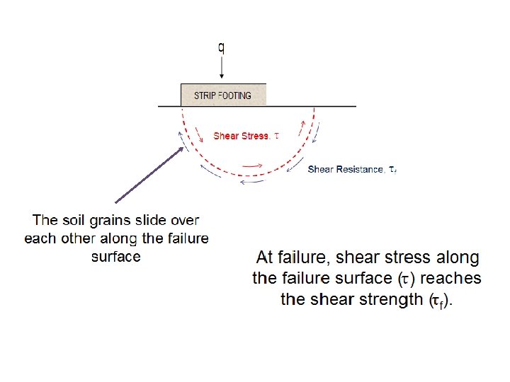
Shear Failure In Soil • The shear strength of a soil can be described as its maximum resistance to shearing stresses. • When this strength is exceeded failure occurs along planes in the soil mass called slip surfaces. • The shear strength of soil has two components : a) Frictional strength, ф b) Cohesive, c
Influencing Factors on Shear Strength • Soil Composition - mineralogy, grain size and grain size distribution, shape of particles, pore fluid type and content, ions on grain and in pore fluid. • Initial State - State can be describe by terms such as: loose, dense, over-consolidated, normally consolidated, stiff, soft, etc. • Structure - Refers to the arrangement of particles within the soil mass; the manner in which the particles are packed or distributed. Features such as layers, voids, pockets, cementation, etc, are part of the structure.
shear failure of soil TYPES OF SOIL FAILURE shear failure of soil Sliding failure of soil Shallow slope stability failure shear failure of soil
Drained condition • Occurs when there is no change in pore water pressure due to external loading • Pore water pressure can drain out of the soil easily, causing volumetric strains in the soil
Undrained condition • Occurs when the pore water pressure is unable to drain out of the soil • Rate of loading is much quicker than the rate at which the pore water pressure is able to drain out of the soil • The tendency of soil to change volume is suppressed • Clays have low hydraulic conductivity, hence most often assumed to be under undrained during loading or construction period in short term, and the shear strength must be analyzed accordingly.
Stress increment Isotropic confinement stress Excess pore pressure DRAINED UNDRAINED
Mohr-coulomb failure criterion f is the maximum shear stress the soil can take without failure, under normal stress of .
Mohr-coulomb failure criterion (cont’)
Peak and Residual-Strength Envelopes for clay
Graphical representation of Mohr. Coulomb failure criteria Normal Case
Granular (non-cohesive) soil Failure envelopes of cohesion less soil
Saturated, plastic clays
Shear stress, τ vs. effective stress, σ’ Nearly linear Slightly non-linear Hence, use idealized linear function a) τ intercept of the line is c’ b) slope of the line is φ’
Shear strength of saturated sands & gravel Little / no excess pore water Under typical static loading Introduction pressure ( k high) Changes in the state of stress of soil cause the voids to expand / contract, water easily flows in / out Hence, u = hydrostatic pore water pressure & s analyses may be based on drained condition and effective stress Under dynamic loads (e. g earthquak e) Sand may not drain quickly enough to dissipate all excess pore water pressure Hence, evaluate s under undrained condition
Determining & φ’and gravels, c’ = 0 • Saturated c’ sands • Determine φ’ by conducting field / lab test • Typical values of φ’ • φ’ increase as unit weight increase • Gravels stronger than sands • Well graded soils stronger than poorly graded soils • Presence of silt decrease the φ’ (because particles are smoother, lower coefficient of friction)
Value of σ’ • In most design prob, as the state of stress of soil change, the shear and normal stresses also change. • Hence σ’ at beginning of loading and at the end is different • Example of situation : • External load, P is applied • Vertical total stress, σz increase • Pore water pressure, u constant (rapid drainage) • Vertical effective stress, σ’z increase at same rate as σz • S also increase • Shear stress, τ also will induces
Shear strength of saturated clays Evaluation of shear strength of clay is more difficult than sand gravel: • Greater volume changes during loading • Low k, undrained cond, excess pore water pressure (short term) • Excess pore water pressure dissipated, drain condition (long term) • Generally weaker than sand & gravel, more often cause problems.
When performing shear strength analysis, need to assess drainage condition 3 possibilities: • CASE I : Shear strength under drained condition • CASE II : Shear strength under undrained condition with positive excess pore water pressures • CASE III: Shear strength under undrained condition with negative excess pore water pressures
Simply evaluate c’ & φ’ using test Easiest to evaluate CASE I Two situations Shear strength can be determined, s = c’ + σ’ tan ф’ Loading very low w. r. t drainage, no excess pore water pressure generated Long time after loading, excess pore water pressure have dissipated
+ve because increase in mean normal stress Cannot compute values of σ’ at failure or s using total stress Mohr coulomb failure s = c. T + σ tan ф. T CASE II If soil truly saturated and undrained ф. T = 0. Shear strength is undrained shear strength, su s = c. T Called as ‘ф = 0 analysis’ Hence, su = c. T
-ve because decrease in mean normal stress CASE III Gradually dissipated but it cause corresponding loss in shear strength also Hence will affect factor of safety, F F = s/τ
Shear strength evaluation
DIRECT SHEAR TEST Top Platen Normal load Load cell to measure shear force Motor Drive Porous plate Rollers
DIRECT SHEAR TEST (cont’) • Only slow drained tests are performed in this test. Shearing rate for clays must be chosen to prevent excess pore pressures building up. For sands and gravels tests can be performed quickly. • Tests on sands and gravels are usually performed dry. Water does not significantly affect the (drained) strength. • If there are no excess pore pressures and as the pore pressure is approximately zero the total and effective stresses will be identical.
Advantages of Direct Shear Test • Easy and quick test for sands and gravels • Large deformations can be achieved by reversing shear direction. This is useful for determining the residual strength of a soil. • Large samples may be tested in large shear boxes. Small samples may give misleading results due to imperfections (fractures and fissures) or the lack of them. • Samples may be sheared along predetermined planes. This is useful when the shear strengths along fissures or other selected planes are required.
Disadvantages of Direct Shear Test • Non-uniform deformations and stresses in the specimen. The stress-strain behavior cannot be determined. The estimated stress may not be those acting on the shear plane. • There is no means of estimation pore pressures so effective stresses cannot be determined from undrained tests • Undrained strengths are unreliable because it is impossible to prevent localized drainage without high shearing rates. • In practice shear box tests are used to get quick and crude estimates of failure parameters.
Direct shear test Analysis of test results Note: Cross-sectional area of the sample changes with the horizontal displacement 32
Direct shear tests on sands Shear stress, t Stress-strain relationship Dense sand/ OC clay tf tf Loose sand/ NC clay Expansion Compression Change in height of the sample Shear displacement Dense sand/OC Clay Shear displacement Loose sand/NC Clay 33
Direct shear tests on sands Shear stress, t How to determine strength parameters c and f Normal stress = s 3 Normal stress = s 2 tf 3 tf 2 tf 1 Normal stress = s 1 Shear stress at failure, tf Shear displacement Mohr – Coulomb failure envelope f Normal stress, s 34
Direct shear tests on clays In case of clay, horizontal displacement should be applied at a very slow rate to allow dissipation of pore water pressure (therefore, one test would take several days to finish) Shear stress at failure, tf Failure envelopes for clay from drained direct shear tests Overconsolidated clay (c’ ≠ 0) Normally consolidated clay (c’ = 0) f’ Normal force, s 35
Example 12. 1 • Direct shear tests were performed on a dry, sandy soil. The size of the specimen was 50 mm x 19 mm. Test results as follows: Test no. Normal force (N) Normal Shear stress σ = force at σ’ (k. N/m 3) failure (N) Shear stress at failure ζ (k. N/m 3) 1 89 35. 6 53. 4 21. 4 2 133 53. 2 81. 4 32. 6 3 311 124. 4 187. 3 74. 9 4 445 178 267. 3 106. 9
Exercise • A drained shear box test was carried out on a sandy clay and yielded the following results: • Area of shear plane = 60 mm x 60 mm • Determine the apparent cohesion and angle of friction for the soil.
Example 12. 2 • Following are the results of four drained direct shear tests on an overconsolidated clay • Diameter of specimen = 50 mm • Height of specimen = 25 mm Test no. Normal force (N) Shear force at failure, Speak (N) Residual Shear force Sresidual (N) 1 150 157. 5 44. 2 2 250 199. 9 56. 6 4 550 363. 4 144. 5 • Determine the relationships for peak shear strength (ζf) 3 102. 9 and residual shear 350 strength (ζr)257. 6
Exercise • The following results were recorded during shear box tests on specimens of a sand compacted to the same initial density : Normal load (N) 110 216 324 432 Ultimate Shear load (N) 66 131 195 261 Peak shear load (N) 85 170 253 340 • Determine the peak and ultimate angles of friction and the angle of dilation
Triaxial Test Deviator Load Confining cylinder Cell water Rubber Membrane O-ring Seals Porous Filter Disc Cell pressure Pore Pressure and volume change
Triaxial Test (cont’) • Depending on whether drainage is allowed or not during i) initial isotropic cell pressure application and ii) shearing • There are 3 types of triaxial tests i) consolidated drained (CD) test ii) Consolidated undrained (CU) test iii) Unconsolidated Undrained (UU) test
Consolidated Drained (CD) Test (slow test) • Drainage valves OPEN during consolidation as well as shearing phases. • Complete sample drainage is achieved prior to application of the vertical load. • The load is applied at such a slow strain rate that particle readjustments in the specimen do not induce any excess pore pressure. • Since there is no excess pore pressure total stresses will equal effective stresses. • Very slow shearing to avoid build-up of pore pressure • Can give the value of c’ and φ’ • c’ and φ’ can be used for analyzing fully drained situations for long term stability of very slow loading)
Example 12. 3 • A consolidated-drained triaxial test was conducted on a normally consolidated clay. The results are as follows : • σ3 = 276 k. N/m 2 • (Δσd)f = 276 k. N/m 2 Determine a) Angle of friction, φ’ b) Angle ϴ that the failure plane makes with the major principal plane
Exercise • A drained triaxial compression test carried out on three specimens of the same soil yielded the following results : Test no. 1 2 3 Cell pressure (k. Pa) 100 200 300 Deviator stress at failure (k. Pa) 210 438 644 • Draw the shear strength envelope and determine the peak strength parameters, c’ and ф’p, assuming that the pore pressure remains constant during the axial loading stage
Example 12. 4 • Refer example 12. 3 • A) Find the normal stress σ’ and the shear stress f on the failure plane • B) Determine the effective normal stress on the plane of maximum shear stress Solution refer page 453
Example 12. 5 • The equation of the effective stress failure envelope for normally consolidated clayey soil is f = σ’ tan 30°. A drained triaxial test was conducted with the same soil at a chamberconfining pressure of 69 kn/m 2. Calculate the deviator stress at failure • Solution refer page 454
Example 12. 6 • The results of two drained triaxial test on a saturated clay follow : • Specimen I : σ3 = 70 k. N/m 2 (Δσd)f = 130 k. N/m 2 • Specimen II σ3 = 160 k. N/m 2 (Δσd)f = 223. 5 k. N/m 3
Consolidated Undrained (CU) Test • Apply σ3 and wait until the soil consolidates • Drainage valves OPEN during consolidation phase but Closed during the shearing phase. (Drainage and consolidation is allowed to take place during the application of the confining pressure σ3). • Loading does not commence until the sample cases to drain (or consolidate). • This test can simulates long-term as well as shortterm shear strength for cohesive soils if pore water pressure is measured during the shearing phase. • Pore pressure develops during shear to measure σ’ • Also gives c’ and ɸ’
Exercise • The following results were obtained from undrained tests on specimens of a saturated normally consolidated clay. Determine : Cell pressure (k. Pa) 100 200 300 Ultimate deviator stress (k. Pa) 137 210 283 Ultimate pore pressure (k. Pa) 28 86 147 (a) the effective stress parameters c’ and ф’c (b) The critical state parameter M
Exercise • The following results were obtained from undrained tests on specimens of an overconsolidated clay : Cell pressure (k. Pa) 100 250 400 Deviator stress at failure (k. Pa) 340 410 474 Deviator pore pressure (k. Pa) -42 64 177 • Determine the effective stress parameters c’ and φ’p
Unconsolidated Undrained (UU) Test (quick test) • Pore pressure develops during shear. Pore pressure is not measured, thus σ’ is unknown • Analyse in terms of σ can gives the values of Cu and φu • σ3 and Δσ are applied fast so the soil does not have time to consolidate • The test is performed with the drain valve closed for all phases of the test ( water is not allowed to drain) • For this test, ф = ф’ = 0
CD Test CU Test UU Test
Advantages of Triaxial Test • • Easy to control drainage Useful stress-strain data Can consolidate sample hydrostatically Can simulate various loading conditions
Disadvantages of Triaxial Test • Apparatus more complicated than other types of tests • Drained tests on fine grained soils must be sheared very slowly
Unconfined compression test • Axial compressive load applied to specimen until it fails • Cross-sectional area at failure : Af = A 0 / 1 -εf where Af = cross-sectional area of failure A 0 = initial cross-sectional (πd 2/4) εf = axial strain at failure Figure : Loading and failure mode in an unconfined compression test.
• No lateral confinement, so σ3 = 0 • Unconfined compressive strength : qu = P f / A f where Pf = normal load at failure Af = cross-sectional area at failure • Undrained shear strength : su = Pf / 2 Af
Vane Shear Test • Vane shear test is commonly used to measure the shear Torque and angular displacement scale strength and sensitivity of clay • This test is useful when the soil Handle to is soft and its water content is apply torque Sample nearer to liquid limit such as Vane clay. Laboratory vane test • Suitable for determination of insitu undrained shear strength of non-fissured fully saturated clay Classification of soil based on sensitivity
Advantages of Vane Shear Test • Very rapid and • inexpensive
Disadvantages of Vane Shear Test • Not applicable to soils with fissures, silt seams, varves, other defects, or less than 100% saturation • Sample disturbance not systematically accounted for
Worked Example
Worked Example Using data given, compute shear strength, s on horizontal and vertical planes at Point A, B and C
Solution Point A vertical effective stress, σz’ = ∑ H – u σz’ = [(17. 0 x 3) + (17. 5 x 1. 1)] – (9. 8 x 1. 1) = 59. 5 k. Pa s = c’ + σ’ tan ф’ = 10 + (59. 5 tan 28 o) = 41. 6 k. Pa horizontal effective stress, σx’ = K σz’ σx’ = (0. 54)(59. 5) = 32. 1 k. Pa s = c’ + σ’ tan ф’ = 10 + (32. 1 tan 28 o) =27. 1 k. Pa USING SIMILAR STEPS, COMPUTE FOR POINT B AND C !!
Solution (cont’) • POINT B – Vertical : s = 57. 2 k. Pa – Horizontal : s = 35. 5 k. Pa • POINT C – Vertical : s = 68. 1 k. Pa – Horizontal : s = 54. 4 k. Pa
THANK YOU FOR YOUR ATTENTION