Easy centering and setting system The display unit


- Slides: 19
Easy centering and setting system
The display unit is mounted on the machine with a built in magnet. It is powered by rechargeable battery and the sensor plugs into the unit with a USB connection.
Remove the splash cover of the guide bushing to reveal the outside diameter of the sleeve.
This is where the sensor ring will mount.
The sensor ring is installed with a set screw. This ring also fits the outside of the sub spindle cap. The sensor is in a brass sleeve and held in place by set screws. Never tighten the set screws against the sensor without the brass sleeve. Tighten the set screws enough against the sleeve so that the sensor is held solid.
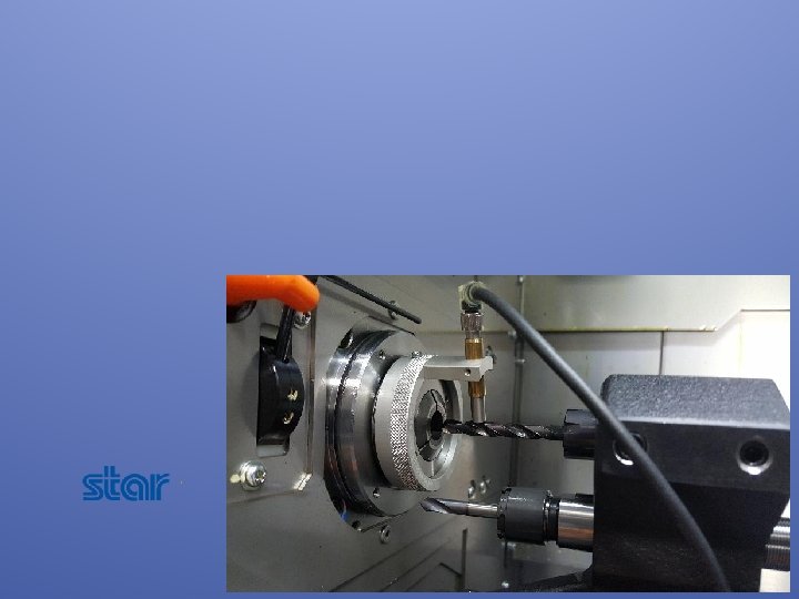
Select the tool and bring it to its center position. In this case, the double tool stations will prevent 360° rotation of the sensor, but this will not be a problem as only 3 measurements are needed to perform the centering. This is true of traditional test indicators, but this sensor is easy to install, easy to ZERO, and does not require removal of the bushing collet. Fixturing a traditional test indicator would be impossible in this space.
Adjust the sensor toward the tool until it is about 1 mm to. 5 mm from the tool – the display unit will begin to display values when the sensor is close enough to read. This is a good time to check the runout of the tool; the display shows real time data. If there is some runout, remove it physically if possible, or rotate the tool to where the high spot is either vertical or horizontal and take it into account when making adjustments.
The unit will initially display some large value in mm.
Press the mm / inch button to switch to inch display if needed.
Rotate the sensor to the bottom vertical centerline measuring position.
Press RESET to zero the display at this position.
Rotate the sensor to the top vertical centerline measuring position.
The display will now show the deviation for the vertical centerline. In our case the value was 0, but if there were a value, move the vertical axis half the displayed amount to bring the tool to the vertical centerline, and check again.
When the vertical centerline has been adjusted as close to 0 as possible, rotate the sensor to the horizontal centerline measuring position.
The display will now show the horizontal deviation from centerline. Move the horizontal axis the full amount to bring it to centerline.
The display shows now the center.
Video of the unit being demonstrated.