
EARTHQUAKE RESISTANT DESIGN FOR MASONRY AND REINFORCED CEMENT


- Slides: 57
EARTHQUAKE RESISTANT DESIGN FOR MASONRY AND REINFORCED CEMENT CONCRETE BUILDINGS
MASONRY STRUCTURE Masonry buildings are brittle structures and one of the most vulnerable of the entire building stock under strong earthquake shaking. Ground vibrations during earthquakes cause inertia forces at locations of mass in the building, which causes damage in structure.
Masonry Units Well burnt bricks conforming or solid concrete blocks conforming having a crushing strength not less than 3. 5 MPa shall be used.
Mortar Cement mortars of 1: 4 to 1: 6 , shall preferably be used for masonry construction for various categories of buildings. When steel reinforcing bars are provided in masonry the bars shall be embedded with cement sand mortar not leaner than 1 : 3 or in cement concrete of grade M 15.
How to Improve Behaviour of Masonry Walls A simple way of making these walls behave well during earthquake shaking is by making them act together as a box along with the roof at the top and with the foundation at the bottom.
A number of construction aspects are required to ensure this box action. 1. Connections between the walls should be good. a) Good interlocking of the masonry at junctions, b) Employing horizontal bands at various levels, particularly at the lintel level. 2. The sizes of door and window openings need to be kept small.
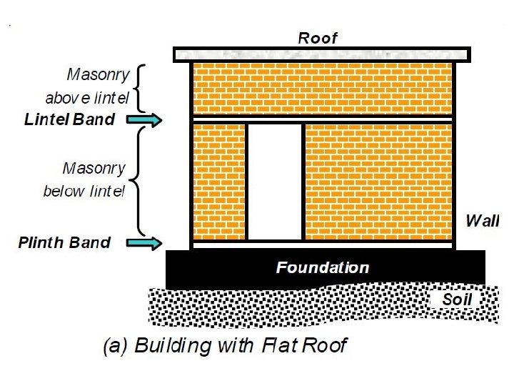
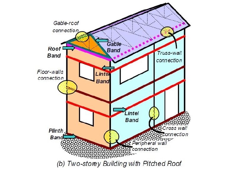
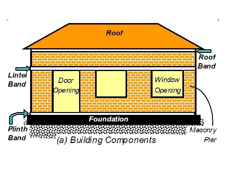
Role of Horizontal Bands The bands are provided to hold a masonry building as a single unit by tying all the walls together. There are four types of bands in a masonry building, 1) Plinth band, 2) Roof band, 3) Lintel band 4) Gable band.
Conti… The lintel band is the most important of all, and needs to be provided in almost all buildings. The gable band is employed only in buildings with pitched or sloped roofs. In buildings with flat reinforced concrete or reinforced brick roofs, the roof band is not required, because the roof slab also plays the role of a band.
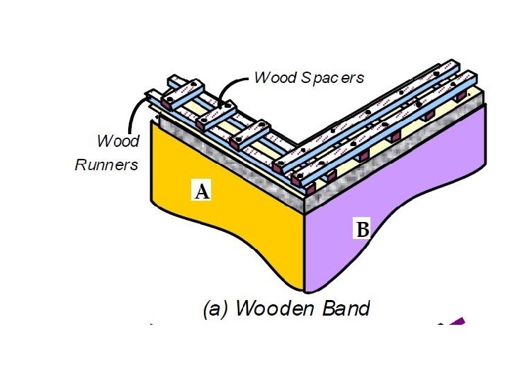
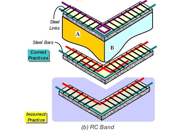
Design of Lintel Bands can be made of wood or of reinforced concrete (RC); the RC bands are the best. The straight lengths of the band must be properly connected at the wall corners. This will allow the band to support walls loaded in their weak direction by walls loaded in their strong direction.
Section and Reinforcement of Band The band shall be made of reinforced concrete of grade not leaner than M 15 or Reinforced brick-work in cement mortar not leaner than 1 : 3. The bands shall be of the full width of the wall, not less than 75 mm in depth and reinforced with steel.
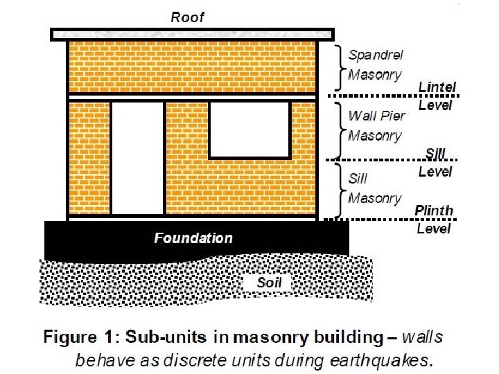
Role of Vertical Reinforcement Even if horizontal bands are provided, masonry buildings are weakened by the openings in their walls. During earthquake shaking, the masonry walls get grouped into three sub-units, namely 1) Spandrel masonry, 2) Wall pier masonry and 3) Sill masonry.
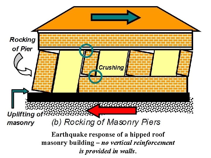
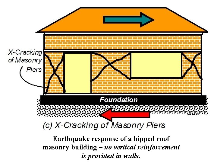
Conti… When the ground shakes, the inertia force causes the small-sized masonry wall piers to disconnect from the masonry above and below. The rocking of a masonry pier can crush the masonry at the corners and the piers are more likely to develop diagonal (X-type) shear cracking.
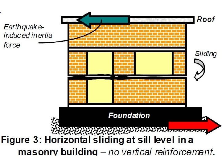
Earthquake response of a hipped roof masonry building – no vertical reinforcement is provided in walls.
Earthquake response of a hipped roof masonry building – no vertical reinforcement is provided in walls.
Conti… During strong earthquake shaking, the building may slide just under the roof, below the lintel band or at the sill level. Sometimes, the building may also slide at the plinth level.
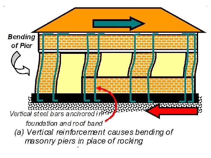
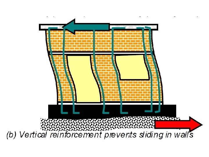
How Vertical Reinforcement Helps Embedding vertical reinforcement bars in the edges of the wall piers and anchoring them in the foundation at the bottom and in the roof band at the top, forces the slender masonry piers to undergo bending instead of rocking.
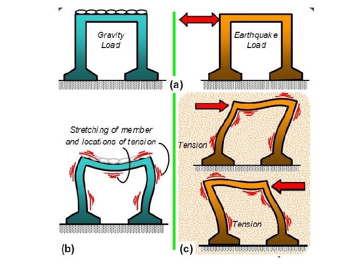
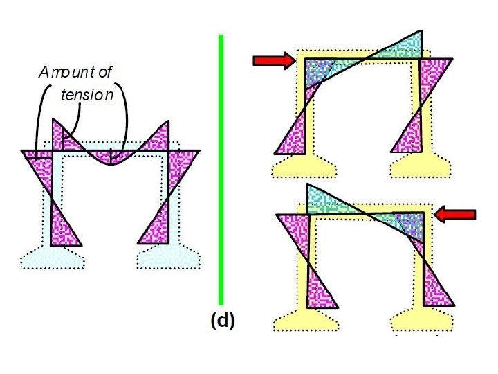
REINFORCED CONCRETE STRUCTURE Under gravity loads, tension in the beams is at the bottom surface of the beam in the central location and is at the top surface at the ends. On the other hand, earthquake loading causes tension on beam and column faces at locations different from those under gravity loading.
Under strong earthquake shaking, the beam ends can develop tension on either of the top and bottom faces. Since concrete cannot carry this tension, steel bars are required on both faces of beams to resist reversals of bending moment. Similarly, steel bars are required on all faces of columns too.
For earthquake resistant, the structure must under go 1. Capacity based design and 2. Ductile design
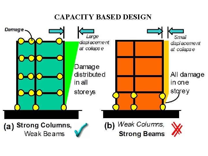
CAPACITY BASED DESIGN
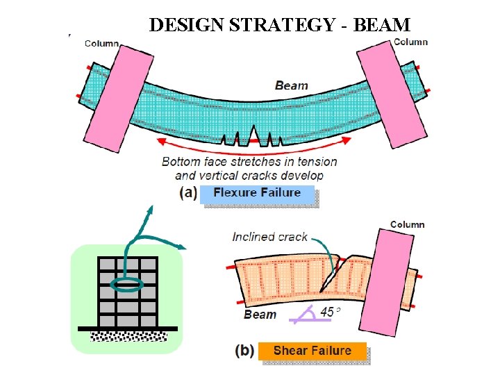
DESIGN STRATEGY - BEAM
Ductile Detailing as per IS 13920 -1993 (Beam) • The factored axial stress on the member under earthquake loading shall not exceed 0. 1 fck. • The member shall preferably have a width-todepth ratio of more than 0. 3. • The width of the member shall not be less than 200 mm. • The depth D of the member shall preferably be not more than 1/4 of the clear span.
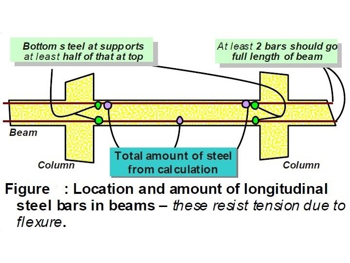
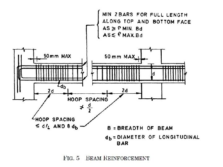
Longitudinal Reinforcement • At least two bars should run throughout the member length at top and bottom. • The positive steel at a joint face must be at least equal to half the negative steel at that face. • The steel provided at the top and bottom face of the member along its length shall be at least equal to 1/4 of the maximum negative moment steel provided at the face of either joint
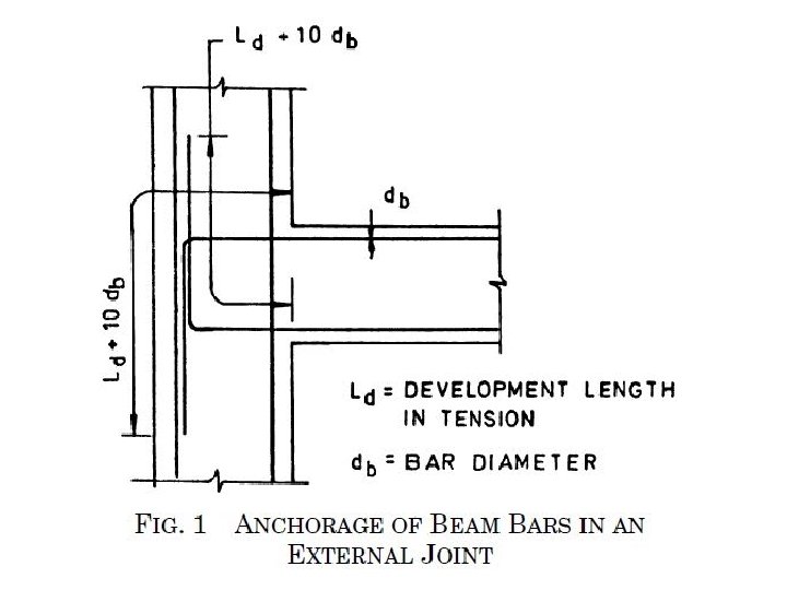
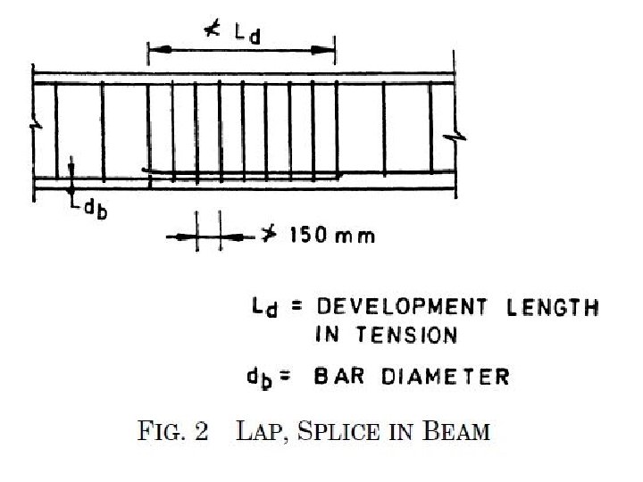
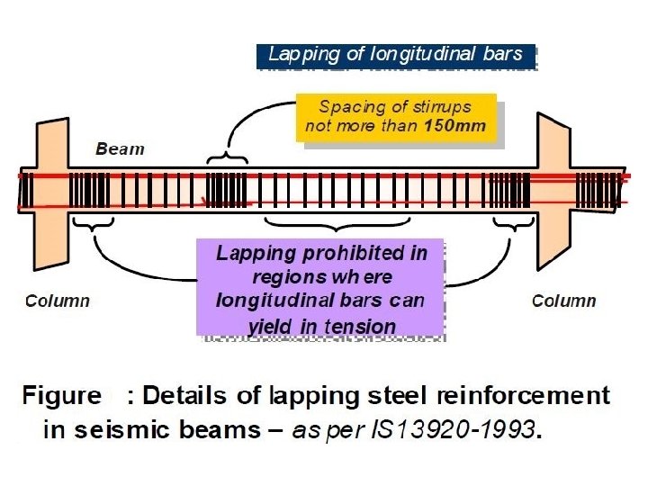
The lap length shall not be less than the bar development length in tension. Lap splices shall not be provided (a) within a joint, (b) within a distance of 2 d from joint face, and (c) within a quarter length of the member where flexural yielding may generally occur under the effect of earthquake forces.
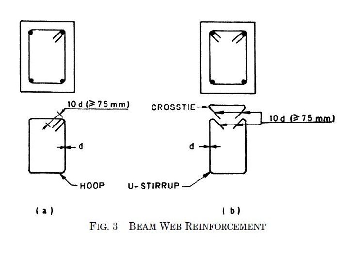
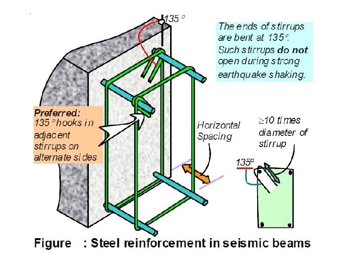
Transverse Reinforcement • The minimum diameter of the bar forming a hoop shall be 6 mm. However, in beams with clear span exceeding 5 m, the minimum bar diameter shall be 8 mm. • A vertical hoop is a closed stirrup having a 135° hook with a 10 diameter extension.
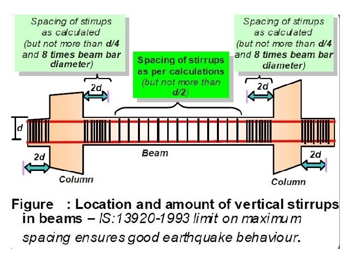
• The spacing of hoops over a length of 2 d at either end of a beam shall not exceed a) d/4, and b) 8 d’ (8 times the diameter of the smallest longitudinal bar); however, it need not be less than 100 mm. • The first hoop shall be at a distance not exceeding 50 mm from the joint face.
Stirrups in RC beams help in three ways, namely (i) They carry the vertical shear force and thereby resist diagonal shear cracks, (ii) They protect the concrete from bulging outwards due to flexure, and (iii)They prevent the buckling of the compressed longitudinal bars due to flexure
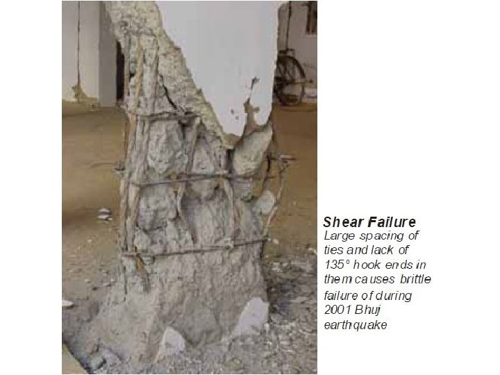
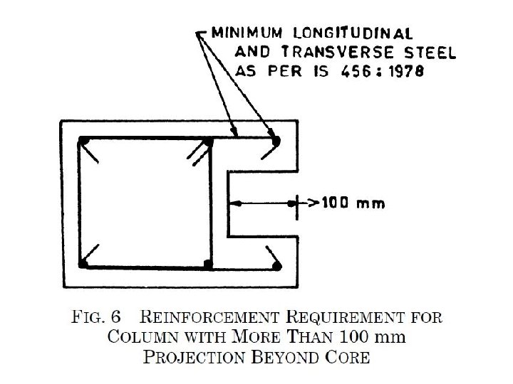
Design strategy - column Columns can sustain two types of Damage, namely 1. Axial-flexural (or combined compression bending) failure and 2. Shear failure. Shear damage is brittle and must be avoided in columns by providing transverse ties at close spacing
DESIGN STRATEGY - COLUMN
Ductile Detailing as per IS 13920 -1993 (Column) • The minimum dimension of the member shall not be less than 200 mm. • The ratio of the shortest cross sectional dimension to the perpendicular dimension shall preferably not be less than 0. 4.
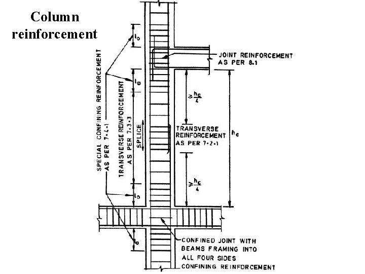
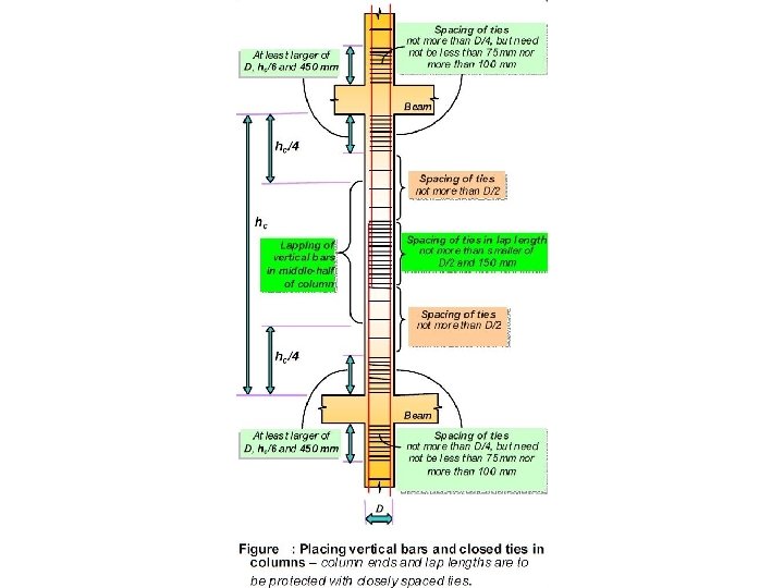
Longitudinal Reinforcement • Lap splices shall be provided only in the central half of the member length. • Hoops shall be provided over the entire splice length at spacing not exceeding 150 mm c/c.
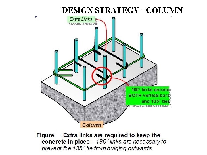
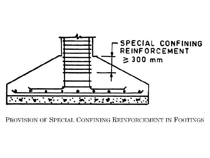
Transverse Reinforcement • Transverse reinforcement for circular columns shall consist of spiral or circular hoops. • In rectangular columns, rectangular hoops may be used. A rectangular hoop is a closed stirrup, having a 135° hook with a 10 diameter extension. • The spacing of hoops shall not exceed half the least lateral dimension of the column.
Column reinforcement