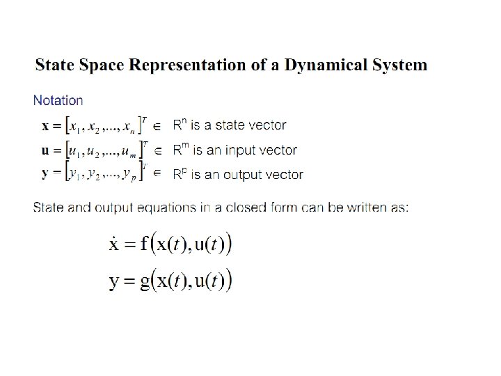
Dynamic system simulation Charging Capacitor The capacitor is


 • Apply Kirchhoff’s loop rule to the circuit after the switch")
 • The current is , substitute to voltage equation • The")


")
")
 • Using Simulink")


 • Example: state space of synchronous generator with")
 • Suppose second order (n=2) equation • We need")

 • Voltage Equation • The flux linkage per second • Mutual")
 • The current can be expressed as • Eqn. 4. 29")
 • Define • Eqn 4. 33 can be expressed as")
 • The flux linkage in integral form")
")


- Slides: 27
Dynamic system simulation
Charging Capacitor • The capacitor is initially uncharged • There is no current while switch S is open (Fig. b) • If the switch is closed at t= 0 (Fig. c) the charge begins to flow, setting up a current in the circ uit, and the capacitor begins to charge • Note that during charging, charges do not jump across the capacitor plates because the gap between the plates represents an open circuit • The charge is transferred between each plate and its connecting wire due to E by the battery • As the plates become charged, the potential difference across the capacitor increases • Once the maximum charged is reached, the current in the circuit is zero
Charging Capacitor (2) • Apply Kirchhoff’s loop rule to the circuit after the switch is closed • Note that q and I are instantaneous values that depend on time • At the instant the switch is closed (t = 0) the charge on the capacitor is zero. The initial current • At this time, the potential difference from the battery terminals appears entirely across the resistor • When the charge of capacitor is maximum Q, The charge stop flowing and the current stop flowing as well. The V battery appears entirely across the capacitor
Charging Capacitor (3) • The current is , substitute to voltage equation • The equation is called Ordinary Differential Equation (ODE) • How to solve this equation? Solve mean we can express the equation into q(t)=….
Solution of ODE • Using Deterministic Approach • Using Numerical approach: 1. Euler’s method 2. Heun’s method 3. Predictor-corrector method 4. Runge-kutta method 5. Etc.
Deterministic Approach • The current is , substitute to voltage equation • Integrating this expression • we can write this expression as
Deterministic Approach • If you integrate to obtain the solution, then you use exact/deterministic method. • However in practical use, we often cannot integrate the function directly. • The numerical approach is often preferable.
Numerical approach
Numerical approach (2)
Numerical approach (3)
Solution in Matlab • Using ODE solver (m-file) • Using Simulink
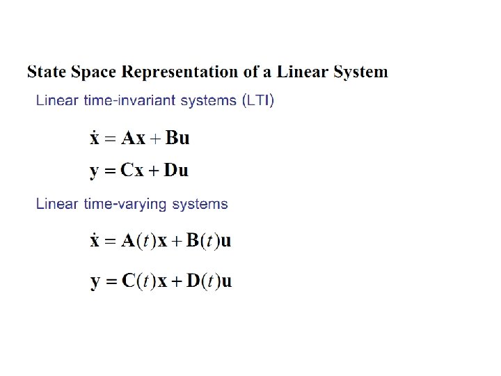
State space of charging capacitor
State space in practical use • In practical use, the A matrix consists of many states space • Simulating the power system is just solving the differential equation of system states and (sometimes) algebraic equation related to load flow. • Normally we use states space in power system simulation such as rotor speed, rotor angle, Flux-linkage change, etc.
State space in practical use (2) • Example: state space of synchronous generator with PSS
Order greater than 1 (n>1) • Suppose second order (n=2) equation • We need to write second order equation into n order first order differential equation • These equations can be solved simultaneously • Homework 1: how to solve this equation for a=b=c=1 using Matlab (use function: ode 45)? With all initial states are zero
Transformer Simulation • Equivalent circuit
Transformer Simulation (2) • Voltage Equation • The flux linkage per second • Mutual flux linkage
Transformer Simulation (3) • The current can be expressed as • Eqn. 4. 29 is now • Collecting mutual flux linkage
Transformer Simulation (4) • Define • Eqn 4. 33 can be expressed as
Transformer Simulation (5) • The flux linkage in integral form
Transformer Simulation (6)
Implementation in Simulink Homework 2: Build this block in Simulink with all initial values of flux linkage are zero
Rules for student • Maksimal terlambat 20 min • Tidak boleh titip absen • Tidak boleh menggunakan barang elektronik kec berhubungan dengan kegiatan perkuliahan
• All materials are posted at http: //husniroisali. staff. ugm. ac. id/