DSTAR Basics DSTAR Basics DIGITAL SMART TECHNOLOGY FOR

D-STAR Basics

D-STAR Basics DIGITAL SMART TECHNOLOGY FOR AMATEUR RADIO

Brief history of D-Star • August, 2003 • December, 2003 First ID 1’s purchased “ICOM Days” at Texas Towers – RP 1 Repeater system installed for demo – First D-Star repeater in country • February, 2005 • Dayton, 2006 Installation of first 2 Internet Gateways RP 2/ID 1 Promotion from ICOM Release of RP 2000 V, RP 4000 V FRRL and NSRC installation efforts begin • • FRRL joins Gateway network as system #12 D-STAR Homebrew radio, Dongle announced Consolidated D-STAR Network 100 th Gateway system and over 2, 000 users February, 2007 Dayton, 2007 October, 2007 November, 2007

Growth through October, 2007

What is D-STAR ? • D-STAR 1200 Mhz started with the ID-1

What is D-STAR ? • D-STAR 1200 Mhz started with the ID-1 – D-STAR is actually Two different modes • Wide DIGITAL DATA DD – 125 Khz • Narrow DIGITAL VOICE DV - 6. 25 Khz • Narrow DV mode also has 1200 Baud included • The ID-1 also has traditional NBFM capability

What is D-STAR ? • D-STAR 440 and 144 Mhz • ONE mode DV • Narrow DIGITAL VOICE DV - 6. 25 Khz • Narrow DV mode also has 1200 Baud included but this capability is different than the High Speed Digital Data available for 1200 Mhz • Wide DIGITAL DATA DD – 125 Khz is too wide for use on 2 meters and is not available for 440

What is D-STAR ? • D-STAR 440 and 144 Mhz • DV DIGITAL VOICE • This DIGITAL VOICE mode is what the majority of us think of when we refer to as “ D-STAR “ • DV is the 4800 baud 0. 5 GMSK mode • We will come back to the topic of high speed DIGITAL DATA or DD D-Star. • The DD or High speed wide mode is 128 Kb/s

What is D-STAR The radio emission is 0. 5 GMSK Gaussian Minimum Shift Keying 4800 Baud data rate of the radio channel • • Includes voice encoded at 2400 Baud rate Includes addressing (callsigns) for routing Includes FEC – forward error correction 990 Baud Includes 1200 Baud digital data payload

D-STAR Spectral Efficiency

D-STAR Basics How is D-Star Similar to FM Operation?

Similar to FM • Channelized frequencies by convention • Range is about 15 – 20% more than FM • Operation is on VHF / UHF – Mobile and Portable operation – Power levels 5 -50 watts normal – Actual coverage depends on terrain – Demodulators can receive only one signal at a time, there is a capture effect at play

Similar to FM • Every station can demodulate all D-Star transmissions • Nothing is “ scrambled “ • A station which presents a properly formatted signal to a repeater input will be repeated – User registration is only required for gateway operation, not for normal repeater use – A “double” will cause loss of intelligibility

D-STAR Basics How is D-Star Different from FM Operation?

Different from FM • The D-Star format combines – – 2400 BAUD VOICE STREAM 1200 BAUD SLOW DATA STREAM 900 BAUD Forward Error Correction – FEC Routing information in the form of FOUR CALLSIGNS • • THE ORIGINATION THE DESTINATION THE FIRST ROUTING THE NEXT ROUTING MYCALL URCALL RPTC 1 RPTC 2

Different from FM • The D-Star format combines – Additional ID on the MYCALL of 4 characters • The MYCALL will look like “NA 9 A _ _ _ / Joe_” • The “/Joe_” portion is not used for routing – 15 Character transmitted user message separate from the 1200 Baud data stream – GPS NEMA code Lat/Long information • ICOM 2820 has optional internal GPS-Rx • ICOM IC-92 AD has optional GPS-Rx in microphone • IC-91 AD and ID-800 can be fed NEMA-0184 stream from standard GPS receiver

Different from FM • FOUR CALLSIGNS – THE ORIGINATION – THE DESTINATION – THE FIRST ROUTING – THE NEXT ROUTING MYCALL URCALL RPTC 1 RPTC 2 » The callsign is 7 characters long » The 8 th position of the call denotes the PORT for repeater systems

It is Different from FM How do we get the CALLSIGNS into the radio?

Front Panel Programming Push the Menu/Lock Button When the Digital Board UT-121 is installed OR if the IC-91 was an IC-91 AD when it was manufactured THEN the top Menu will read “ CALL SIGN “ selecting this choice will then display the CALL SIGN menu

Front Panel Programming TO Navigate the MENU use the up/down and left/right arrow keys When EDITING a field, the character to be changed will be a flashing BLOCK…. the character can be changed with the up/down (2 & 8 keys) OR with the upper small frequency selector knob, navigation in the editing field is manipulated with the left/right (4 & 6 keys). At any time the editing is complete – the RETURN (#5) key can be pressed

INSTANT Programming

INSTANT Programming

Different from FM • CALLSIGNS – The station’s call is up to 7 Characters long • By definition the MYCALL must be the legal callsign of the originating station – The 8 th Character of a callsign is the PORT of a DStar Repeater • The Ports are by convention – – A B C G is 1200 Mhz or BLANK is routed as an “A” is 440 Mhz is 144 Mhz is the GATEWAY COMPUTER use only in RPTC 2

Different from FM • FOUR CALLSIGNS • For local simplex Operation – – THE ORIGINATION THE DESTINATION THE FIRST ROUTING THE NEXT ROUTING MYCALL URCALL RPTC 1 RPTC 2 W 9 XA _ _ _ CQCQCQ not used » The callsign is 7 characters long » The 8 th position of the call denotes the PORT for repeater systems

D-STAR Basics Routing

What is Routing?

What is Routing? • Gateway system – Is a computer running Linux that interfaces the repeater controller to the distant D-Dstar repeater’s gateway. – The gateway system functions as a specialized router for the 4800 baud D-Star data streams

What is Routing? • Gateway system – A single Gateway system serves all repeater “ports” within one D-Star system • D-star systems usually have 144, 440 and 1200 Mhz DV – Digital Voice Systems • . The gateway will also route high speed data to and from the DD - High Speed Digital Data Systems at the 128 kb/s data rate !!!

W 9 CEQ FRRL Batavia, IL Blue Box – WRT-54 G Linux PC – Gateway D-Star Controller 2 Meter DV Repeater 440 Mhz DV Repeater Cavities & Duplexer

How is Traffic routed? • Gateway system – Associates the user’s callsign with a discrete IP number within the gateway system • Accomplished by user registration – Associates distant repeater callsigns with discrete IP number within the system • Assigned when the gateway system is commissioned

How is Traffic routed? • Gateway system – The IP numbers used in routing are NEVER needed beyond the inner workings of the gateway system – All that is needed are the CALLSIGNS which are available to the user’s “front panel”

Gateway Routing • Gateway system – Tracks each user’s callsign last location – Routes traffic for that user to the last known repeater and port

What is Routing? • Two Routing Methods – Site Routing • Where you want to talk – Specific System/Gateway and Port – User Routing • Who you want to talk – Specific User

Site Routing • Callsign of the System – – – W 9 CEQ: Batavia, IL K 5 TIT: Dallas, TX W 4 DOC: Atlanta, GA K 6 MDD: Mt. Diablo, CA N 7 IH: Bellevue, WA (ICOM America HQ) – G 7 ICM: ICOM UK – VK 8 RAD: Darwin, Australia • Callsign Programming – – MYCALL = W 9 XA RPT 1 = W 9 CEQ---B RPT 2 = W 9 CEQ---G URCALL = /VK 8 RADB • Results – My call would be routed from the W 9 CEQ repeater, over the gateway, and come out on the UHF module in Darwin Australia

User Routing • Callsign of the System – – – W 9 CEQ: Batavia, IL K 5 TIT: Dallas, TX W 4 DOC: Atlanta, GA K 6 MDD: Mt. Diablo, CA N 7 IH: Bellevue, WA (ICOM America HQ) – G 7 ICM: ICOM UK – VK 8 RAD: Darwin, Australia • Callsign Programming – – MYCALL = W 9 XA RPT 1 = W 9 CEQ---B RPT 2 = W 9 CEQ---G URCALL = N 5 MIJ • Results – W 9 XA’s voice and data communications would be routed from the N 7 IH repeater, over the gateway, and come out on the last RF module N 5 MIJ used in Dallas, TX

User Routing • HOW DO YOU KNOW WHERE N 5 MIJ is? • http: //www. dstarusers. org • http: //w 9 ceq. illinoisdstar. org
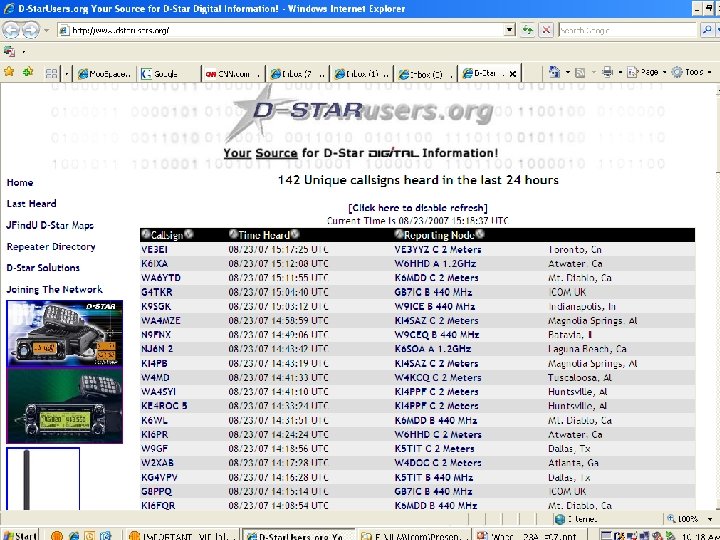

User Routing • HOW DO YOU KNOW WHERE W 9 XA is? • http: //www. dstarusers. org • http: //www. w 9 ceq. net • http: //www. w 9 ceq. com

W 9 CEQ ‘s local log
 • Goal – To talk to as many D-STAR users")
User Routing (Fun Stuff) • Goal – To talk to as many D-STAR users as possible. • User Callsigns – – – N 5 MIJ: Dallas, TX KJ 4 VO: Atlanta, GA W 4 OZK: Huntsville, AL K 6 BIV: Mt. Diablo, CA N 9 JA: Bellevue, WA VK 8 HF: Darwin, Australia • Callsign Programming – MYCALL = N 9 FNX – RPT 1 = W 9 CEQ---B – RPT 2 = W 9 CEQ---G – URCALL = N 5 MIJ Then – URCALL = KJ 4 VO Then – URCALL = K 6 BIV Then – URCALL = VH 8 HF • Result – Both Voice and Data Communications routed to the appropriate recipient! Note – the 1200 baud data stream is carried along with the voice payload………

Route with the system controller • Goal – To talk to friends on another band, same system. • System Configuration – – 23 cm DV 23 cm DD 70 cm DV 2 m DV Port A Port B Port C • Callsign Programming – – MYCALL = KK 9 H RPT 1 = NS 9 RC---B RPT 2 = NS 9 RC---A URCALL = CQCQCQ • Result – Both Voice and Data Communications routed to NS 9 RC Port A, which is 1200 Mhz!
 • PROBLEM – N 9 JA travels TOO much")
User Routing (More Fun Stuff) • PROBLEM – N 9 JA travels TOO much • How do we keep regular contact? • N 9 JA’s Travel Schedule – – – Monday: Dallas, TX Tuesday: Atlanta, GA Wednesday: Tuscaloosa, AL Thursday: San Francisco, CA Friday: Bellevue, WA • Callsign Programming – – MYCALL = W 9 XA RPT 1 = W 9 CEQ _ _ B RPT 2 = W 9 CEQ _ _ G URCALL = N 9 JA • Result – Both Voice and Data Communications routed to the appropriate recipient regardless of location!

What is D-STAR ? • JARL’s Open Protocol – Japanese Amateur Radio League – Goal • Advancement of the hobby • Spectrum Efficiency • Experiment with Voice and Data

D-STAR Basics QUESTIONS ?
 • EVERY CALLSIGN FIELD will have 8 characters! – The")
8 Characters (A reminder) • EVERY CALLSIGN FIELD will have 8 characters! – The 8 th character is a port designator for the System/Gateway fields (RPT 1 or RPT 2) • NOTE: IF left blank, the system assumes PORT A is used! – DO NOT use a letter or number in the 8 th position in the USER callsign.
- Slides: 45