DSP in FPGA Topics Signal Processing State of


")


")


 Matrix operations require all matrix element")
: Estimated 15 % logic unusable (due to data")


- Slides: 48
DSP in FPGA
Topics Signal Processing State of the Art Flexibility Multi-Channel Friendly IP Block Example: FIR Filter Simulink Equalizer Routing Challenge DSP Slice Multiplication Modes IP Blocks Data-path with Constant Cache FFT Example Other Examples: Resources When not to use Floating Point Example FP: Adder Hardware Circuit Constant Cache Example: FIR Filter DSP on FPGA Considerations FPGA Applications with DSP milestones PDSP Architecture PDSP vs FPGA Routing Resources: Altera vs. Xilinx Example: Matrix Multiplication Hypothesis and Rule’s of Thumb Results Paper Analysis
Signal Processing Transform Most DSP or manipulate analog or digital signal. frequent application: filtering. has replaced related traditional analog signal processing systems in many applications.
FPGA’s Applications
Milestones Cooley and Tukey 1965 Efficient algorithm to compute the discrete Fourier Transform (DFT) PDSP 1970 Compute (fixedpoint) “multiply-andaccumulate” in only one clock cycle Today PDSPs: Floating-point multipliers, barrel shifters, memory banks, zerooverhead interfaces to A/D and D/A Converters
PDSP Architecture Single-DSP implementations have insufficient processing power for today’s system’s complexity. Multiple-chip systems: more costly, complex and higher power requirements. Solution: FPGAs
Managing Resources & Design Reliability
FPGA vs. PDSPs RISC paradigm with MAC Advantage: multistage pipeline architectures can achieve MAC rates limited only by speed of array multiplier. Dominate applications that required complicated algorithms (e. g. several ifthen-else constructs) FPGA Implement MAC at higher cost. High-bandwith SP applications through multiple MAC cells on one chip. Algorithms: CORDIC, NTT or error-correction algorithms Dominate more front-end (sensor) applications FIR filters, CORDIC algorithms FFTs
FPGA Advantages 1. Ability to tailor the implementation to match system requirements. 2. Multiple-channel or high -speed system: take advantage of the parallelism within the device to maximize performance, 3. Control logic implemented in hardware
Fir Filter Example
FPGA
State of the Art (Xilinx)
Flexibility How many MACs do you need? For example, in FIR Filter, FPGAs can meet various throughput requirement
Multi-Channel Friendly Parallelism enables efficient implementation of multichannel into a single FPGA. Many low sample rate channels can be multiplexed and processed at a higher rate.
Resources Challenge: How to make the best use of resources in most efficient manner?
DSP 48 E 1 Slice Flexibility 2 DSP 48 E 1 slices per tile Column Structure to avoid routing delay Pre-adder, 25 x 18 bit multiplier, accumulator Pattern detect, logic operation, convergent/symmetric rounding 638 MHz Fmax
Multiplication Modes Each DSP block in a Stratix device can implement: Four 18 x 18 -bit multiplications, Eight 9 x 9 -bit multiplication, or One 36 x 36 -bit multiplication While configured in the 36 x 36 mode, the DSP block can also perform floatingpoint arithmetic.
DSP IP Portfolio Comprehensive Constraint Driven
IP Block example Overclocking automatically used to reduce DSP slice count. Quick estimates provided by IP compiler GUI Insures best results for your design requirements.
Altera: DFPAU D-Floating Point Arithmetic Coprocessor. Replaces C software functions by fast hardware operations – accelerates system performance Uses specialized algorithms to compute arithmetic functions
Altera: DFPAU
Hardware circuit for FP adder Breaking up an number into exponent and mantissa requires pre- and postprocessing Comprises Alignment (100 ALMs) Operation (21 ALMs) Normalization (81 ALMs) Rounding (50 ALMs) Normalization and rounding together occupy half of the circuit area How to improve this?
When not to use Floating Point? Algorithms designed for fixed point Greater precision and dynamic range are not helpful because algorithms are bit exact. E. g. Transform to go to frequency domain in video codecs has some form of a DCT (Discrete Cosine Transform). Designed to be performed on a fixedpoint processor and are bit exact. Also, when precision is not as important as speed
Constant Cache Some applications load data from memory once and reuse it frequently Could pose a bottleneck on performance. What i. e. FFT can we do? Copying data to local memory may not be enough, as each work group would have to perform the copy operation Solution Create a constant cache that only loads data when it is not present within it, regardless of which workgroup requires the data
Datapath with a Constant Cache
Example FFT Large computation, can be precomputed
Equalizer Example
Routing Challenge
Routing challenge Designed performance achieved only when the datasets are readily accessed from fast on-chip SRAMs. For large data sets, the main performance bottleneck is the off-chip memory bandwidth. With DRAM, you can process data on stages with only a portion of dataset that fits on chip operated on at a time. Available memory bandwidth determines performance.
Routing Resources Xilinx: more local routing resources Altera: wide buses Synergistic Also with DSP because most DSP algorithms process data locally. has value, because normally wide data vectors with 16 to 32 bits must be moved to the next DSP block.
Example: Matrix Multiplication Double-precisions FP cores (64 bits) Matrix operations require all matrix element calculations to complete at the same time. These parallelized or “vector” operations will occur at the slowest clock speed of all the FP functions in the FPGA.
Routing Challenge Hypothesis (constrained performance prediction): Estimated 15 % logic unusable (due to data path routing, routing constraints, etc. ) Estimated 33 % decrease in FP function clock speed Extra 24, 000 ALUs for local SRAM memory controller and processor interface 39 +, 39 X Clock Speed: 200 Mhz Performance: 15. 7 GFLOPS Peak is: 300 MHZ 25. 5 GFLOPS
Routing Challenge Considerations: Latency of transfer of A and B matrix from microprocessor to local FPGA SRAM not included in benchmark time. Challenge when using all double-precision FP cores: feeding them with data on every clock cycle. When dealing with double-precision 64 -bit data, and parallelizing many FP arithmetic cores, wide internal memory interfaces are needed.
Routing Challenge: Results Average sustained throughput : 88 percent. The GFLOPS calculation then is 200 MHz * 81 operators * 88 percent duty cycle = 14. 25 GFLOPS. 40 multiply and 40 adder tree cores – result every clock cycle Five additional adder cores used for blocking implementation: one value per clock cycle Lower than expectation – due to the time needed to read and write values to the external SRAM. With multiple SRAM banks providing higher memory bandwidth, the GFLOPS would be closer to the 15. 7 GFLOPS number. Power: The expected 15 GFLOPS performance of the Stratix EP 2 S 180 FPGA running at 30 W is close to the sustained performance of a 60 -W 3 -GHz Intel Woodcrest CPU
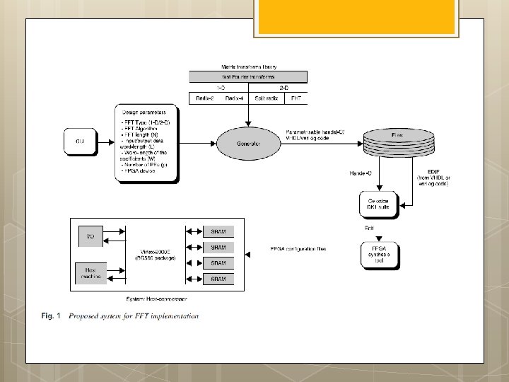
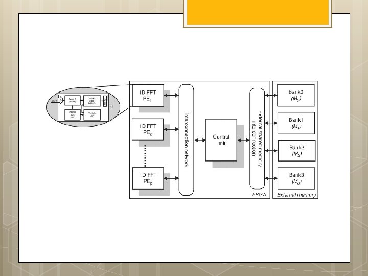
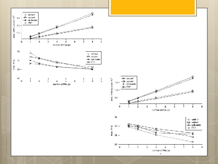
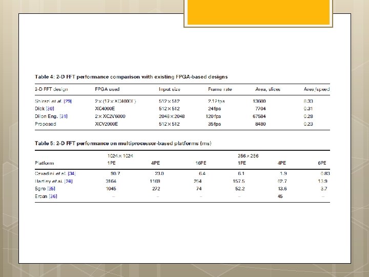
FPGA implementations of fast Fourier transforms for real-time signal & image processing I. S. Uzun, A. Amira and A. Bouridane
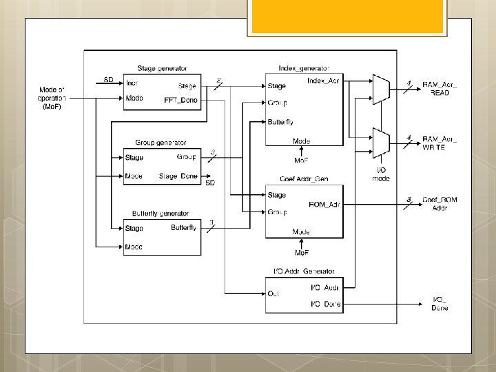
Functional block diagram of 1 -D FFT processor architecture
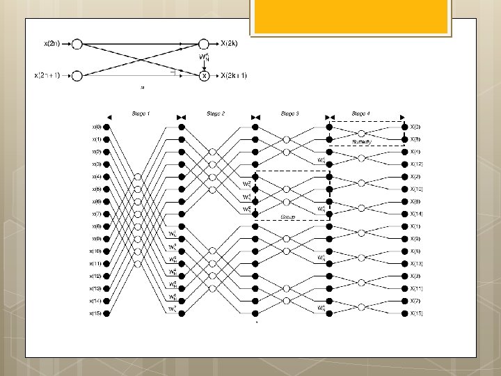
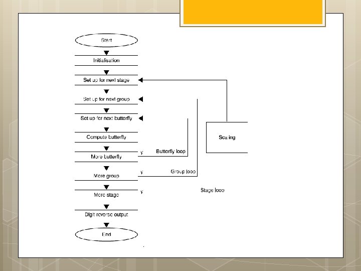
AGU: Radix-2 DIF FFT w s : ¼ 1 for stage : ¼ log 2 ðNÞ to 1 step 1 fnnstage loop m : ¼ 2^stage is : ¼ m=2 w index 0 : ¼ 0 for group : ¼ 0 to n m step m fnngroup loop for bfi : ¼ 0 to is l fnnbutterfly loop Index 0 : ¼ r þ j IEE Proc. -Vis. Image Signal Process. , Vol. 152, No. 3, June 2005 295 Index 1 : ¼ Index 0 þ is; } w index 0 : ¼ w index 0 þ w s; } w s : ¼ w s 1