DRILLING MACHINE SHANAS BASHEER LECTURER GPTC ADOOR DRILLING

DRILLING MACHINE SHANAS BASHEER LECTURER GPTC ADOOR

DRILLING MACHINE • Drilling is the operation of producing circular hole in the work-piece by using a rotating cutter called drill. • The machine used for drilling is called drilling machine • Similar operations like boring, reaming, counter boring, counter sinking, tapping etc. can also be performed with the drilling machine. • As the machine exerts vertical pr. to originate hole it is called drill press.

Major Parts of Drill Machine • Base • Column • Table • Head • Spindle drive and feed mechanism

Parts of drilling machine

Major parts of Drill Machine 1. Base – It is a heavy casting on which vertical column is mounted. 2. Column – It is the vertical member of the drilling machine. It supports table and the head including driving mechanism. 3. Table – It is mounted on the column. ‘T’ slots are provided on it to clamp the work piece on it. The position of the table can be adjusted vertically on the column to hold the work piece at different height below the drill tool. It can be set in various position in horizontal plane 4. Head – It is mounted on the top of the column. It consists of driving and feeding mechanism for the spindle. 5. Spindle – Spindle is a vertical shaft which holds the chuck and drill. Rotary motion of the spindle is given directly to the tool to cut the material from the work piece. It is made of alloy steel. 6. Spindle drive and feed mechanism – Multiple speeds may be obtained by a step cone pulley drive or by gear. Feed mechanism provided in drilling machine is either by quick reverse hand feed or by sensitive hand feed. The feed movement may be controlled by hand or power.

TYPES OF DRILLING MACHINE 1. Portable drilling m/c 2. Sensitive drilling m/c a. bench mounting b. floor mounting 3. Upright drilling m/c a. Round column section b. Box column section 4. Radial drilling m/c a. plain b. Semi universal c. Universal 5. Gang drilling m/c 6. Multiple spindle 7. Automatic drilling 8. Deep hole drilling a. Vertical b. Horizontal

Portable Drilling Machine • Small compact unit and used for drilling holes in work pieces in any position, which cannot be drilled in a standard drilling machine • Can accommodate drills up to 12 mm in diameter.

Sensitive Drilling Machine • Small machine, used for drilling small holes in light jobs • High rotating speed of the drill and hand feed • Drill holes from 1. 5 to 15 mm • Operator senses the travel of drill(as hand feed). So called as sensitive drilling machine

Pillar type/Up-Right Drilling Machine • Larger and heavier than a sensitive drilling machine • For drilling medium sized work pieces • Large no of spindle speed and feed available • Drill holes up to 50 mm • Table can move vertically and radially

Radial Drilling Machine • It the largest and used for drilling medium to large and heavy work pieces. • Consists of a vertical column with an arrangement to raise or lower and to revolve arm (360 °) • Drill head mounted on radial arm can be moved horizontally on guide ways and clamped at desired position

Gang drilling machine • No of single spindle drilling machine columns are placed side by side • A series of operation may be performed by shifting the work from one position to other on work table • Adapted for production work

Multiple drilling machine • To drill no of holes in a piece of work simultaneously

TOOL HOLDING DEVICES 1. 2. 3. 4. Directly fitting in spindle Drill chuck Drill Sleeve Drill Socket
 to receive taper shank of")
Spindle • Spindle hole have standard taper (1: 20) to receive taper shank of tool • Shank is forced into tapered hole and tool is gripped by friction • To ensure positive drive tang or tongue of tool fits into a slot at the end of taper hole • Tool is removed by pressing a tapered wedge known as drift into slotted hole of the spindle

DRILLING MACHINE SPINDLE

DRILL SLEEVE • Drill spindle is used for holding only one size of shank • Drill sleeve is used if taper shank of tool is smaller than tapered hole in spindle • Outside taper of sleeve matches with drill spindle taper • Inside taper holds the tool shank of smaller size

DRILL SOCKET • Used to hold tool when tapered tool shank is larger than the spindle taper • Longer in size than sleeve • Taper shank of socket conforms to taper of drill spindle • It has a tapered hole larger than drill spindle taper which holds larger shank tool

DRILL CHUCK • Holding smaller size drills • Used to hold different sizes of tool shanks • Have tapered shank which fit into drilling machine spindle

WORK HOLDING DEVICES 1. 2. 3. 4. 5. 6. 7. Drill vices Parallel bars Step blocks Angle plate V-Blocks Clamps and T- bolts Drill jigs

DRILLING VICE & PARALLEL BAR • Most common method to hold round, square or odd-shaped rectangular work piece • Clamped between fixed and movable jaws • Parallel blocks are placed below the work so that drill pass completely through the work without damaging work table • Two lugs are provided at the base for clamping it securely to work table

CLAMPS & T-BOLT Used to hold work directly to drill table or an angle plate for drilling

ANGLE PLATE & V- BLOCK • Angle plate – L-shaped piece of cast iron or hardened steel machined to accurate 90° – May be bolted or clamped to table • V-blocks – Made of cast iron or hardened steel – Used in pairs to support round work for drilling • Step blocks – Used to provide support for outer end of clamp – Various sizes and steps to accommodate different work heights

ANGLE PLATE & V- BLOCK

Step Block

Drill jigs – Used in production for drilling holes in large number of identical parts – Jig can hold and locate the work, guide the tool – Eliminate need for laying out a hole location

TYPES OF DRILLS § Flat drill § Straight fluted drill § Twist drill 1. a. parallel shank drill b. taper shank drill § Core drill § Oil hole drill • Centre drill

FLAT DRILL § Made from round tool steel which is forged to shape and ground to size, then hardened and tempered § Used to produce holes in softer material like wood, plastics etc. § Two cutting edge with cutting angle varies from 90° to 120 ° and relief or clearance angle at cutting edge is 3° to 8° § Disadvantage: Diameter is reduced as a result of sharpening of edges. § Chips will not automatically come out of holes

STRAIGHT FLUTED DRILL § It has grooves running parallel to the drill axis. § Chips do not come out of holes automatically, so it is not popular § It is used for cutting brass, copper or other softer material

TWIST DRILL § Most commonly used § Flutes help in removing chips upward from the drilled holes § Usually made from high speed steel § Twist drill may have parallel shank or taper shank § Parallel shank is again divided into short series or jobbers, stub series, long series depending on drill length

CORE DRILL § Used for enlarging cored, punched or drilled holes § Cannot originate hole in solid material as cutting edge do not extend to centre of drill § Metal removed by chamfered edge at the end of each flute § Produce better finished holes than ordinary two fluted drill

OIL TUBE DRILL § Drilling deep holes § It has oil tubes running length wise spirally through the body of the drill to carry oil to cutting edges

CENTRE DRILL § Two fluted twist drill with straight shank § Used to make centre holes on end of shaft

DRILLING MACHINE OPERATIONS • Drilling: Operation of producing cylindrical hole by removing metal by rotating edge of cutting tool(drill) • Before drilling, the hole is located by drawing two lines at right angle and a centre punch is used to make an indentation • A suitable drill is held in the drilling machine and correct cutting speed is selected. • Cutting fluid is provided as the cut is started. • The rotating drill is made to feed into the job.

DRILLING MACHINE OPERATIONS

DRILLING MACHINE OPERATIONS Reaming • Operation of sizing and finishing a pre-existing hole • It is performed by means of a multi tooth cutting tool called reamer. Boring • Operation of enlarging a hole by means of an adjustable cutting tool • A boring tool is employed for this purpose.

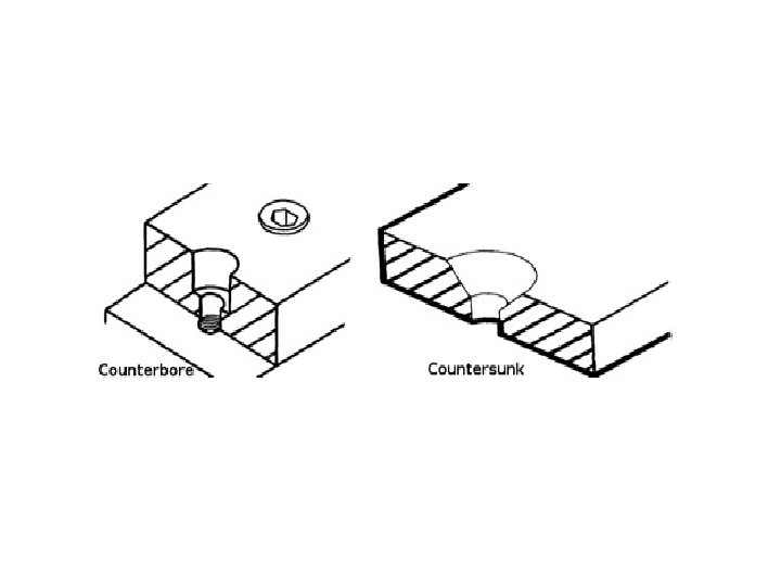
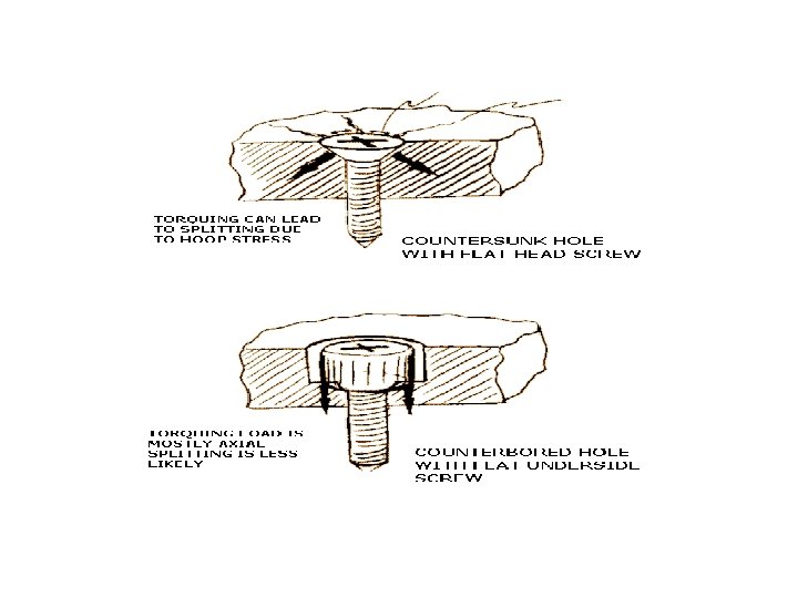
DRILLING MACHINE OPERATIONS Counter Boring • Operation of enlarging the end of a hole cylindrically • It is done to accommodate head of bolts, studs etc. • The tool used is known as counter-bore. Counter Sinking • Operation of making a cone shaped enlargement at the end of a hole • It provides recess for flat head screw or counter sink rivet head

DRILLING MACHINE OPERATIONS

DRILLING MACHINE OPERATIONS

DRILLING MACHINE OPERATIONS Spot facing • Operation of smoothing and squaring the surface around a hole for the seat for a nut or head of screw • Counter bore or special spot-facing tool is used Tapping • Operation of cutting internal threads by using a tool called a tap. • A tap is similar to a bolt with accurate threads cut on it. • Minor diameter of thread is drilled and then tapping is done • Tap Drill size(Dia. of hole to be drilled), D =T -2 d(Indian Standard specification) T =diameter of tap or bolt, d=depth of thread • By thumb rule, Tap drill size =Outside diameter x. 8

DRILLING MACHINE OPERATIONS Trepanning

DRILLING MACHINE OPERATION Trepanning • Tool resembles a hollow tube with cutting end on one end and solid shank at other end • Tool is fed into the job, a circular grove is made and finally blank is removed to produce the hole • Used for producing deep holes of larger diameter.

CUTTING SPEED •

CUTTING SPEED • Depends upon 1. Material being drilled 2. Cutting tool material 3. Quality of surface finish 4. Efficient use of cutting fluid 5. Method of holding the work 6. Size, type , rigidity of the machine

FEED • The feed of a drill is the distance the drill moves into the work at each revolution of the spindle. It is expressed in mm. • Also expressed in feed per minute i. e. , the axial distance moved by the drill into the work. Depends upon Material being cut, rigidity of the machine and job, depth of hole, type of finish desired, power available, range of feeds available.

DEPTH OF CUT •

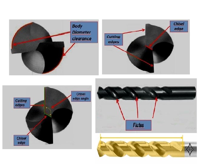
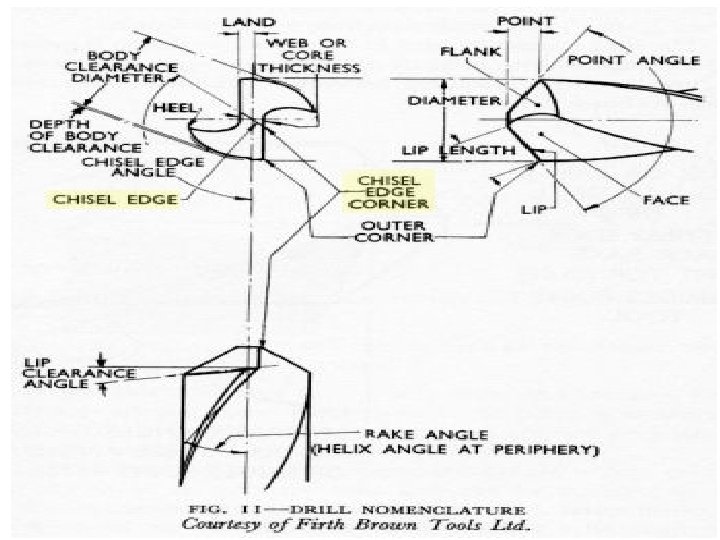
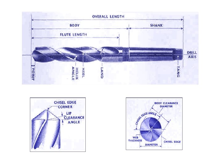
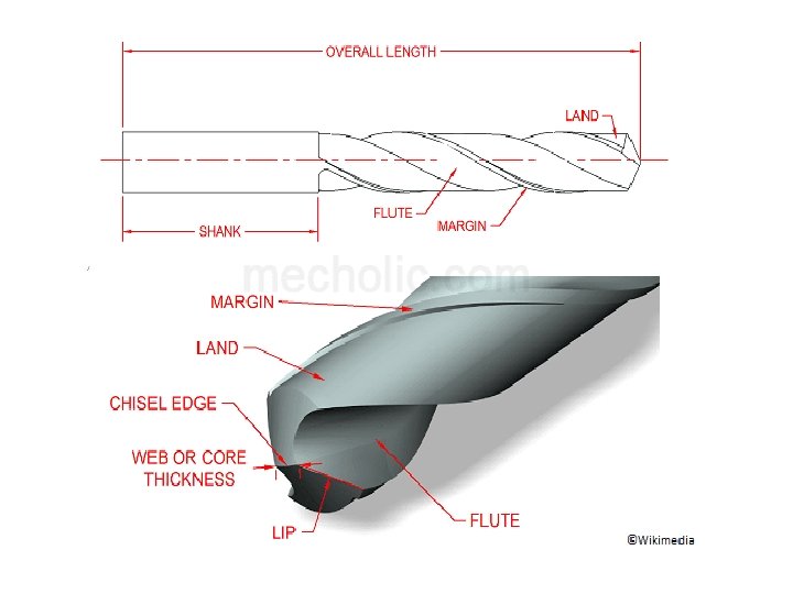
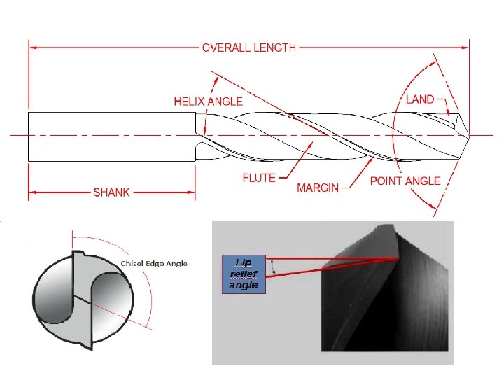
Twist drill nomenclature • Axis is the longitudinal centre line of drill. • Shank : portion of the drill by which it is held and driven • Tang: Flattened end which fits into drift slot in spindle. Ensures positive drive of drill and spindle • Body : Portion of the drill, which extends from the extreme cutting end to commencement of neck • Body clearance is that portion of the body surface reduced in diameter to provide diametric clearance. • Flutes are the grooves in the body of the drill which permits removal of chips, permit cutting fluid to reach the lips.

• Face : Portion of the flute surface adjacent to the lip on which the chip impinges as it is cut from the work. • Flank is that surface on a drill point which extends behind the lip to the following flute. • Chisel edge : edge formed by the intersection of the flanks. • Heel : Edge formed by intersection of flute surface and body clearance • Lip or cutting edge is the edge formed by the intersection of the flank and face • Flute length The length of flute measured from the drill point to the end of flute run out • Web : The thickness measured across the base of flutes. The point end of web forms the chisel edge. • Lands : Cylindrically ground surface on leading edge of drill flute.

• Drill diameter : Largest diameter measured across the top of lands. • Chisel Edge angle: Angle formed between chisel edge and cutting lips. It is generally 125° to 135° • Helix angle or Rake angle is the angle between the leading edge of the land the drill axis. • Lip clearance angle is the angle formed by the flank and a plane at right angles to the drill axis • Point angle is the included angle of the cone formed by the lips. Usually 118 °.

Twist drill nomenclature

Drilling machine specification • Portable drilling machine – specified by max. dia of drill that can hold • Sensitive and up right drilling m/c – specified by dia of largest work piece that can be accommodated • Radial drilling machine – specified by length of radial arm and column dia Heavy duty drilling m/c is specified by • Max. drill dia • Spindle taper(Morse no. ) • Table diameter • Max. spindle travel • No. of spindle speed and feed available • Power input • Floor space required • Net weight etc.

Boring Bar Drilling table Reamer

Use of stepped block

Clamp and T bolt

Previous questions • Different work holding devices in drilling machine • Draw nomenclature of twist drill showing different angles • Draw a neat sketch of a sensitive drilling machine and mark all parts • Difference between drilling and reaming(2 mark) • List different drilling machine operation • Write different types of drilling machine • Draw a line diagram of radial drilling machine and mark all parts • List tool holding devices in drilling machine • Draw drill jig and explain the features • Explain cutting speed and feed
- Slides: 61