DRILLING ENGINEERING Drilling String Design 1 6 Rotary


 If the drilling fluid is air and the torque required to")
- Slides: 13
DRILLING ENGINEERING Drilling String Design
1. 6 Rotary System Main Parts: 1. Swivel 2. Kelly 3. Rotary Drive 4. Rotary Table 5. Drill Pipe 6. Drill Collar 1. Swivel: Supports the weight of the drillstring and permits rotation i. e. Bail and Gooseneck. 2. Kelly: Square or Hexagonal to be gripped easily. Torque is transmitting through kelly bushings. Kelly saver sub is used to prevent wear on the kelly threads.
Rotary System…. . . 3. Slips: During making up a joint slips are used to prevent drillstring from falling in hole. 4. Rotary Drive: Provides the power to turn the rotary table. * Power Sub: can be used to connect casing. 5. Drill Pipe: Specified by (a) Outer Diameter (b) Weight per foot (c) Steel grade (d) Range Length Range 1 2 3 Length (ft) 18 to 22 27 to 30 38 to 45
Rotary System…. . . * Tool Joint: Female is called Box. Male is called Pin. * Upset : Thicker portion of the pipe. * Internal upset: Extra thick. * Thread Type: Round, tungsten carbide hard facing. 6. Drill Collar: Thick walled heavy steel pipe used to apply weight to the bit. * Stabilizer Subs : Keep drill collars centralized. * Capacity : Volume per unit Length. = Capacity of pipe (1. 13) = Capacity of annulus (1. 14) = Displacement (1. 15)
Capacity and displacement nomenclature
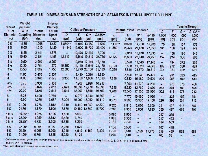
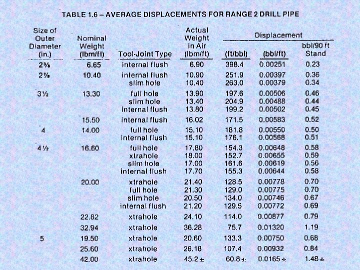
Rotary System…. . . Example 1. 4: A drillstring is composed of 7, 000 ft of 5 -in. , 19. 5 -lbm/ft drillpipe and 500 ft of 8 -in. OD by 2. 75 -in ID drill collars when drilling a 9. 875 -in. borehole. Assuming that the borehole remains in gauge, compute the number of pump cycles required to circulate mud from the surface to the bit and from the bottom of the hole to the surface if the pump factor is 0. 178 bbl/cycle. Solution: For field units of feet and barrels, Eq. 1. 13 becomes
Rotary System…. . . Using Table 1. 5, the inner diameter of 5 -in. , 19. 5 lbm/ft drillpipe is 4. 276 in. ; thus, the capacity of the drillpipe is And the capacity of the drill collars is The number of pump cycles required to circulate new mud bit is given by
Rotary System…. . . Similarly, the annular capacity outside the drillpipe is given by And the annulus capacity outside the drill collars is The pump cycles required to circulate mud from the bottom of the hole to the surface is given by Answer
Components of the rotating system
SLIDES
Equation 4. 25(a) If the drilling fluid is air and the torque required to rotate the bit is low, the radial and tangential stress in the drill pipe may be neglected. For these simplified conditions, the neutral point is the point of zero axis stress. In this case, the minimum length of drill collars Ldc, is given by Fb = the max. force to be applied to the bit during drilling operation. Wdc = the weight per foot of the drilling collars.