DREAM IDEA PLAN IMPLEMENTATION Present to Amirkabir University

DREAM IDEA PLAN IMPLEMENTATION
 & Semnan University Dr. Kourosh Kiani")
Present to: Amirkabir University of Technology (Tehran Polytechnic) & Semnan University Dr. Kourosh Kiani 2 Email: kkiani 2004@yahoo. com Email: Kourosh. kiani@aut. ac. ir Web: aut. ac. com
 R 2 a + _ R 1 c d b R 3 R")
i(t) R 2 a + _ R 1 c d b R 3 R 4 v(t) + + _

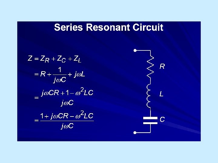
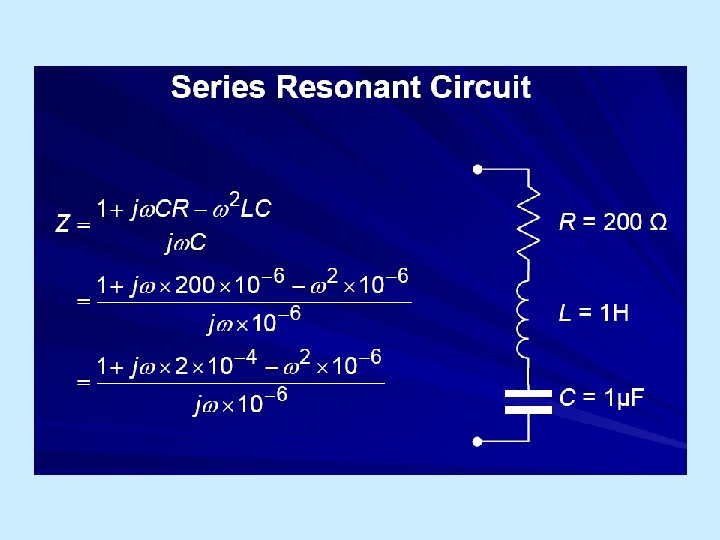
The RLC Series Circuit The effective resistance of the circuit is given by the impedance Z: V=IZ Imax = Vmax / Z Irms = Vrms / Z SI unit of impedance: ohm
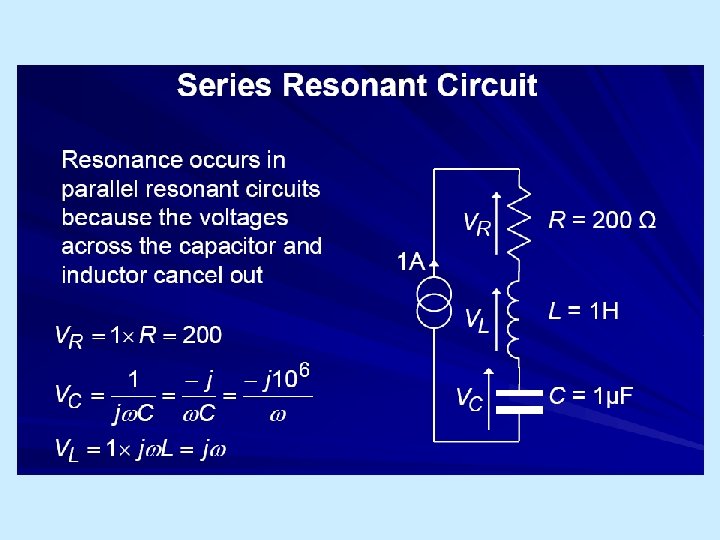
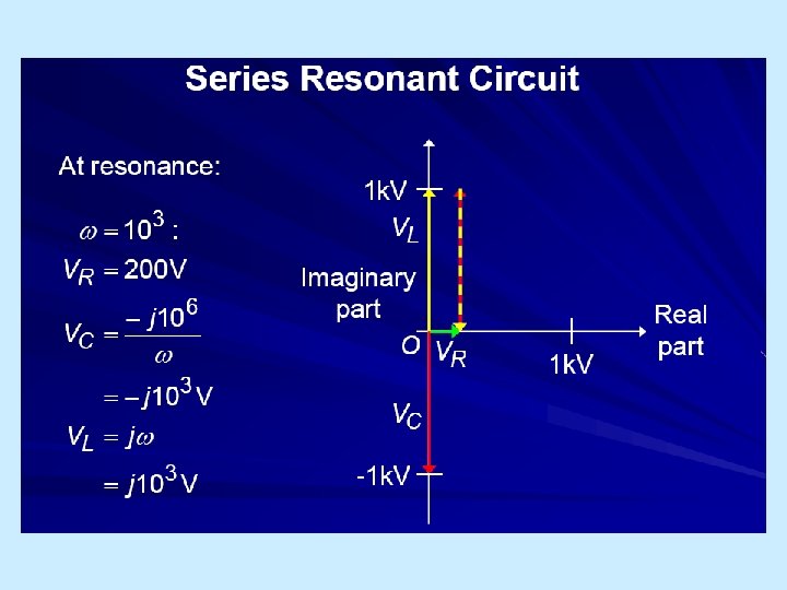
 • Resonance XL=XC VL=VC = VR XC /R")
The RLC Series Circuit w 2=1/(LC) • Resonance XL=XC VL=VC = VR XC /R If XC >>R, at resonance, then VC >>VR VL VR VC

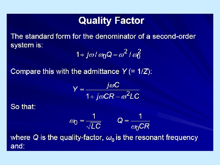
Resonance in a Series RLC Circuit The current in a series RLC circuit is The current will be maximum when XL = XC at a resonance frequency w of

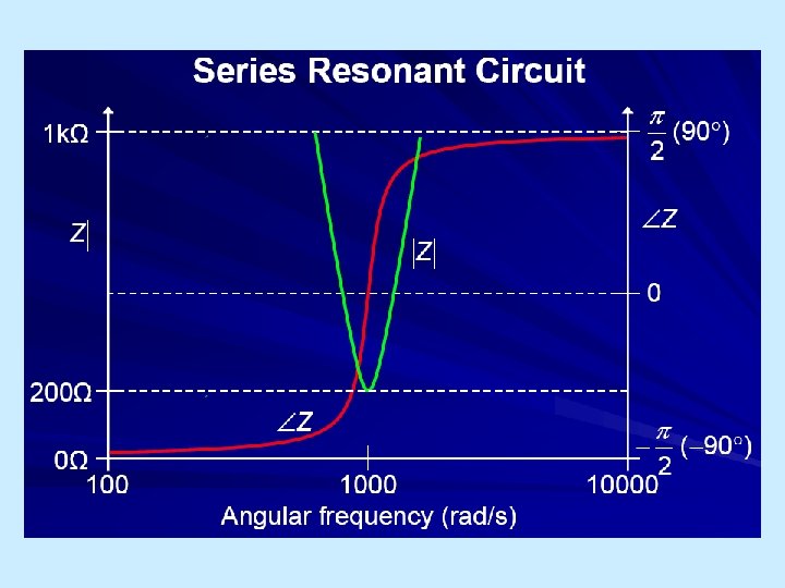
Resonance R is independent of f XL increases with f XC increases with 1/f Z is minimum at resonance frequency! Z R Z: XL and XC subtract XL f 0 Resonance: XL = XC XC

Resonance R is independent of f XL increases with f Power is maximum at resonance frequency! XC increases with 1/f Z: XL and XC subtract Z f 0 Resonance: XL = XC Power

L As the frequency of the circuit is either raised above or lowered below the resonant frequency, the impedance of the circuit: R C Always increases Only increases for lowering the frequency Only increases for raising the frequency Z f 0

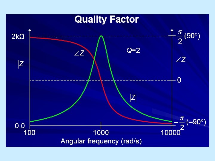
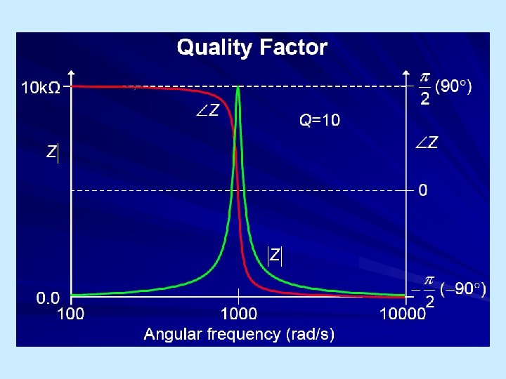
Resonance in an AC Circuit • Resonance occurs at the frequency, ƒo, where the current has its maximum value – To achieve maximum current, the impedance must have a minimum value – This occurs when XL = XC

Resonance, cont • Theoretically, if R = 0 the current would be infinite at resonance – Real circuits always have some resistance • Tuning a radio – A varying capacitor changes the resonance frequency of the tuning circuit in your radio to match the station to be received

Series RLC circuits • In a series RLC circuit, the capacitor voltage and the inductor voltage are always 180 degree out of phase

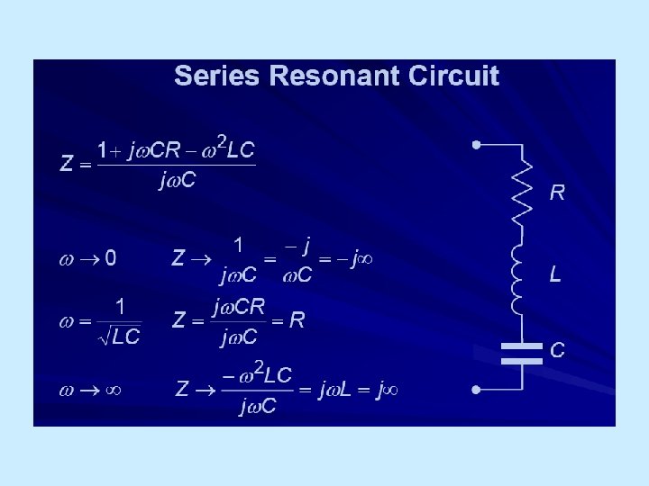
Series RLC circuits • Series resonance

Series RLC circuits • Voltage across C and L are equal in magnitude • The polarities of the voltages across C and L are opposite • No voltage drop from A to B but still current total reactance must be zero

Series RLC circuits • Resonant frequency • Example

Series RLC circuits • The maximum current is • Example

Series RLC circuits • Phase angle

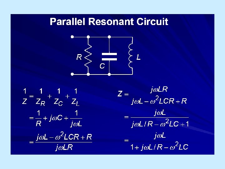
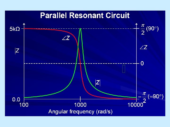
Parallel RLC circuits • Impedance
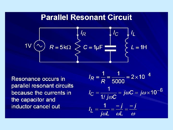
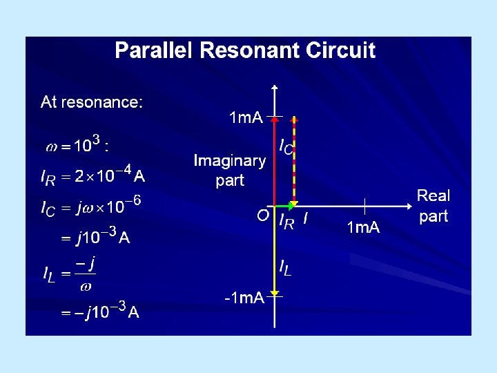
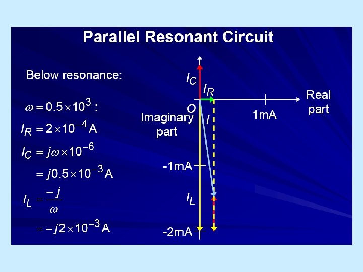
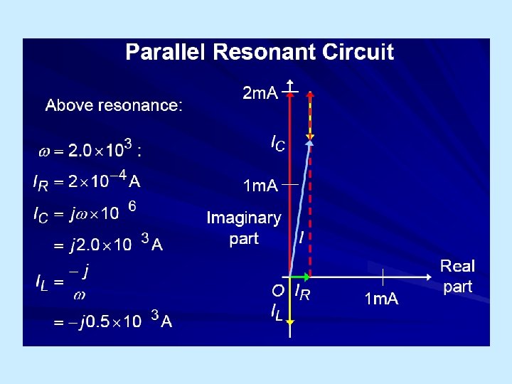


Parallel RLC circuits • Current relationship

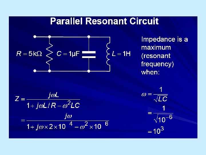
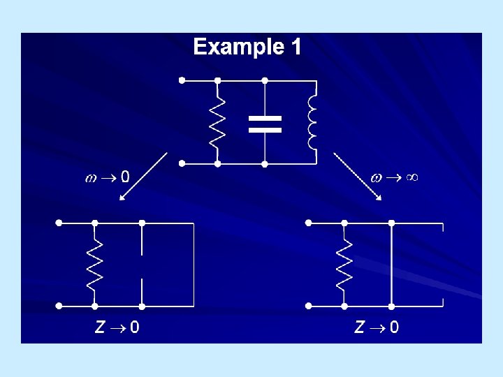
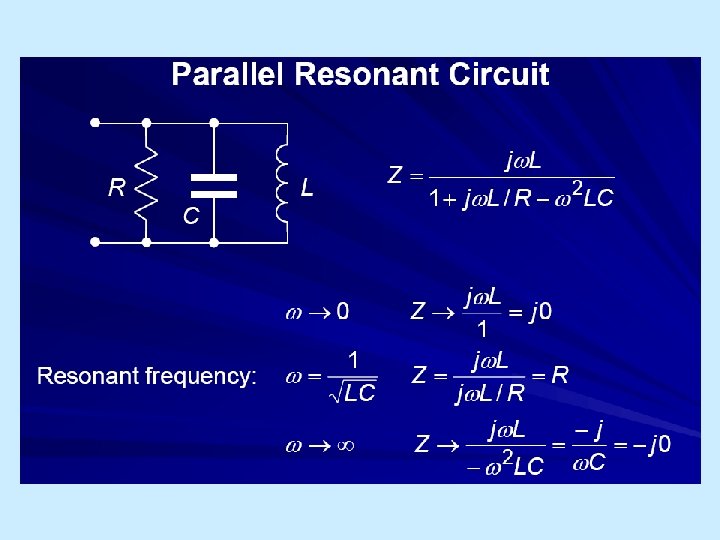
Parallel RLC circuits • Parallel resonance


An RLC circuit is used to tune a radio to an FM station broadcasting at 88. 9 MHz. The resistance in the circuit is 12. 0 Ω and the capacitance is 1. 40 p. F. What inductance should be present in the circuit? Given: The resonance frequency of the circuit should be chosen to match that of the radio station RLC circuit f 0=88. 9 Hz R = 12. 0 W C = 1. 40 p. F Find: L=? This is sufficient to know for a solution, as we know all of the quantities on the right hand side

Questions? Discussion? Suggestions ?

- Slides: 46