DREAM IDEA PLAN IMPLEMENTATION Present to Amirkabir University

DREAM IDEA PLAN IMPLEMENTATION
 & Semnan University Dr. Kourosh Kiani")
Present to: Amirkabir University of Technology (Tehran Polytechnic) & Semnan University Dr. Kourosh Kiani 2 Email: kkiani 2004@yahoo. com Email: Kourosh. kiani@aut. ac. ir Web: aut. ac. com
 R 2 a + _ R 1 c d b R 3 R")
i(t) R 2 a + _ R 1 c d b R 3 R 4 v(t) + + _

++++ +- - - Normal values of capacitance are small. Microfarads is common. For integrated circuits nano or pico farads are not unusual

Typical Capacitors

Capacitors only store and release ELECTROSTATIC energy. They do not “create” The capacitor is a passive element and follows the passive sign convention Linear capacitor circuit representation

Capacitance Law One can also express the voltage across in terms of the current Integral form of Capacitance law Differential form of Capacitance law … Or one can express the current through in terms of the voltage across The mathematical implication of the integral form is. . . Voltage across a capacitor MUST be continuous Implications of differential form? ? DC or steady state behavior A capacitor in steady state acts as an OPEN CIRCUIT

EXAMPLE

CAPACITOR AS ENERGY STORAGE DEVICE Energy is the integral of power If t 1 is minus infinity we talk about “energy stored at time t 2. ” If both limits are infinity then we talk about the “total energy stored. ”

EXAMPLE Energy stored in 0 - 6 msec Charge stored at 3 msec

Find the Voltage

Find the Voltage

FIND THE ENERGY

EXAMPLE Dtermine the Current

EXAMPLE J Energy stored at a given time t Charge stored at a given time C Current through the capacitor Electric power supplied to capacitor at a given time Energy stored over a given time interval A W J

EXAMPLE V C V Energy stored in capacitor at a given time “Total” energy stored in the capacitor J J

EXAMPLE In particular Charge stored at 5 ms Total energy stored Total means at infinity. Hence

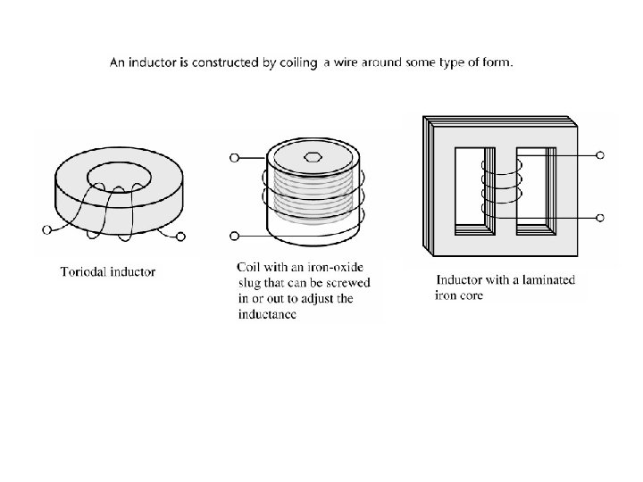
Inductors Inductor are used in electrical circuits because they store energy in their magnetic fields. What is an Inductor? Current A coil of wire that can carry current Current produces a magnetic field Energy is stored in the inductor Flux i

Inductance Formula: N 2 A h L= Inductor formula: Area A = Li N turns = Flux linkage in volt-sec h i = Amperes L = Henries (physical property of inductor) = Flux no. of turns Material of permeability 0 = 4 10– 7 henries/meter can vary between 0 and 10, 000 0

Inductors Flux lines may extend beyond inductor creating stray inductance effects

Typical Inductors

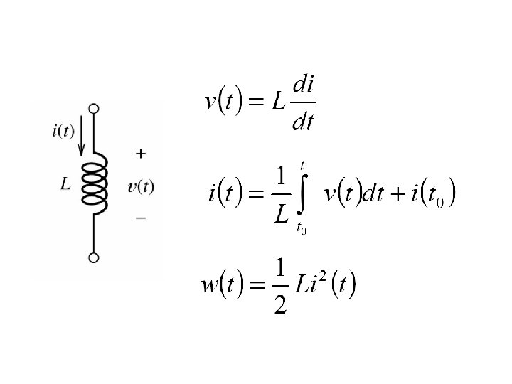
A TIME VARYING MAGNETIC FLUX INDUCES A VOLTAGE Induction law FOR A LINEAR INDUCTOR THE FLUX IS PROPORTIONAL TO THE CURRENT DIFFERENTIAL FORM OF INDUCTION LAW THE PROPORTIONALITY CONSTANT, L, IS CALLED THE INDUCTANCE OF THE COMPONENT INDUCTANCE IS MEASURED IN UNITS OF henry (H). DIMENSIONALLY INDUCTORS STORE ELECTROMAGNETIC ENERGY. THEY MAY SUPPLY STORED ENERGY BACK TO THE CIRCUIT BUT THEY CANNOT CREATE ENERGY. THEY MUST ABIDE BY THE PASSIVE SIGN CONVENTION

Differential form of induction law Integral form of induction law Current MUST be continuous A direct consequence of integral form DC (steady state) behavior A direct consequence of differential form Power and Energy stored W J Current in Amps, Inductance in Henrys yield energy in Joules Energy stored on the interval Can be positive or negative “Energy stored at time t” Must be non-negative. Passive element!!!

EXAMPLE FIND THE TOTLA ENERGY STORED IN THE CIRCUIT In steady state inductors act as short circuits and capacitors act as open circuits

L=10 m. H. FIND THE VOLTAGE EXAMPLE ENERGY STORED BETWEEN 2 AND 4 ms THE DERIVATIVE OF A STRAIGHT LINE IS ITS SLOPE J THE VALUE IS NEGATIVE BECAUSE THE INDUCTOR IS SUPPLYING ENERGY PREVIOUSLY STORED
=2 A. Find i(t), t>0 EXAMPLE Energy stored on the interval")
L=0. 1 H, i(0)=2 A. Find i(t), t>0 EXAMPLE Energy stored on the interval Can be positive or negative Initial energy stored in inductor “Total energy stored in the inductor” Energy stored between 0 and 2 sec
 FOR")
EXAMPLE FIND THE VOLTAGE ACROSS AND THE ENERGY STORED (AS FUNCTION OF TIME) FOR ENERGY STORED IN THE INDUCTOR NOTICE THAT ENERGY STORED AT ANY GIVEN TIME IS NON NEGATIVE -THIS IS A PASSIVE ELEMENT-

EXAMPLE

EXAMPLE L=200 m. H

L=200 m. H EXAMPLE FIND THE POWER NOTICE HOW POWER CHANGES SIGN POWER FIND THE ENERGY IS NEVER NEGATIVE. THE DEVICE IS PASSIVE

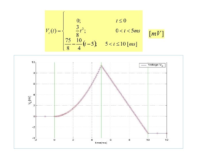
L=5 m. H FIND THE VOLTAGE EXAMPLE

CAPACITOR SPECIFICATIONS CAPACITANCE RANGE p. F » £ C £» 50 m. F IN STANDARD VALUES EXAMPLE GIVEN THE VOLTAGE WAVEFORM DETERMINE THE VARIATIONS IN CURRENT VOLTAGE WAVEFORM

INDUCTOR SPECIFICATIONS INDUCTANCE RANGES » 1 n. H £ L £» 100 m. H IN STANDARD VALUES LEARNING EXAMPLE GIVEN THE CURRENT WAVEFORM DETERMINE THE VARIATIONS IN VOLTAGE CURRENT WAVEFORM

IDEAL AND PRACTICAL ELEMENTS IDEAL ELEMENTS CAPACITOR/INDUCTOR MODELS INCLUDING LEAKAGE RESISTANCE MODEL FOR “LEAKY” CAPACITOR MODEL FOR “LEAKY” INDUCTORS

Energy Storage Elements • Capacitors store energy in an electric field • Inductors store energy in a magnetic field • Capacitors and inductors are passive elements: – Can store energy supplied by circuit – Can return stored energy to circuit – Cannot supply more energy to circuit than is stored • Voltages and currents in a circuit with energy storage elements are solutions to linear, constant coefficient differential equations!

How does it work? How we can store the energy? + + Energy stored in a capacitor. . . + - - … energy density… … energy density. . . + + dielectric - Energy stored in an inductor …. + B - - - E - -

Circuits with Capacitors or Inductors Series Connection of Capacitors Consider the series connection of capacitors as illustrated by Figure The branch characterization of linear-invariant capacitor is + v 1 + v 2 - + vm - i 1 C 1 i 2 C 2 (1) i + v C Using KCL at all nodes, we obtain (2) - Using KVL, we have im Cm Figure: Series connection of capacitors (3) At t=0 (4)
 to (4), we obtain (5) Therefore the equivalent capacitor is given")
Combining Eqs. (1) to (4), we obtain (5) Therefore the equivalent capacitor is given by (6) The series connection of m linear time-invariant capacitors, each with value Ck and initial voltage vk(0), is equivalent to a single linear timeinvariant capacitor with value C, which is given by Eq. (6) and initial voltage (7)

+ C 1 v 1 C 2 v 2 1 = 1 + 1 Ceq C 1 C 2 i – + – C 1 C 2 Ceq = C 1 + C 2

Parallel Connection of Capacitors For the parallel connection of m capacitors we must assume that all capacitors have the same initial voltages, for otherwise KVL is violated at t=0 It is easy to show that for the parallel connection of m linear time invariant capacitors with the same voltage vk(0), the equivalent capacitor is equal to (8) and i See Figure v 1 + - (9) C 1 v 2 + - C 2 • • • vm + + - Cm Figure Parallel connection of linear capacitors v - C

i + v 1 – Capacitors in Parallel: C 1 C 2 + v 2 – Ceq = C 1 + C 2 i = Ceq dv dt

Series Connection of Inductors The series connection of m linear time-invariant inductors is shown in Figure. Let the inductors be specified by (10) + v 1 + v 2 - + vm - i 1 and let the initial currents be ik(0). Using KCL at all nodes, we have (11) i L 1 i 2 L 2 im + v - Thus, at t=0, i(0)=ik(0), k=1, 2, . . , m KCL L requires that in the series connection of m inductors all the initial value of the currents through the inductors must be the same. Using KVL, we obtain Lm Figure Series connection of linear inductors (12)
 to (12), we have (13) Therefore, the equivalent inductance is given")
Combining Eqs. (10) to (12), we have (13) Therefore, the equivalent inductance is given by (14) The series connection of m linear time-invariant inductors each with Lk and initial current i(0), is equivalent to single inductor of inductance with the same initial current i(0). Parallel Connection of Inductors i 1 L 1 i 2 L 2 • • • im i + Lm v - L

Parallel Connection of Inductors We can similarly derive the parallel connection of linear time-invariant inductors shown in Figure. This result is simply expressed by the following equations: (15) and (16) i i 1 L 1 i 2 L 2 • • • im + Lm Figure: Parallel connection of linear inductors v - L

Inductors in Series and Parallel Inductors combine like resistors Series Parallel L 1 L 2 Leq = L 1 + L 2 L 1 L 2 Leq = L 1 + L 2

Summary In a series connection of elements, the current in all elements is the same. The voltage across the series connection is the sum of voltage across each individual element. In parallel connection of elements, the voltage across all elements is the same. The current through the parallel connection is the sum of the currents through each individual element. Type of elements Resistors R=resistance C=capacitance S=elastance Inductors L=inductance Series connection of m elements Parallel connection of m elements

EXAMPLE ALL INDUCTORS ARE 6 m. H

EXAMPLE ALL INDUCTORS ARE 4 m. H CONNECT COMPONENTS BETWEEN NODES

Questions? Discussion? Suggestions ?

- Slides: 53