Drawings and Assemblies Chapter Objectives Understand the basics

Drawings and Assemblies

Chapter Objectives • Understand the basics of Engineering Drawings • Outline the industry standards followed by designers for Engineering Drawings • Introduce the Solid. Works environment to execute Engineering Drawings procedure • Give an overview of assembly concepts used to assemble created parts

Drawings

Dimensioning • The way a designer displays the dimensions on the views implies how to manufacture the part • Hence the designer must have prior knowledge about Drafting and Communication rules – Manufacturing – Common stock shapes available off the shelf – Tolerances –
 2) 3) 4) 5) 6) 7) 8) 9) 10) Minimize")
ASME Abbreviation Rules 1) 2) 3) 4) 5) 6) 7) 8) 9) 10) Minimize using abbreviations Pay attention to foreign use Pay attention to clarity Be aware of duplicates Define when extensively used Take advantage of single use Avoid using non standard abbreviations Follow military rules Use all capital letters Avoid using subscripts

Sample Abbreviations
 2) 3) 4) 5) 6) 7) 8) 9) 10) 11)")
ASME Drafting Rules 1) 2) 3) 4) 5) 6) 7) 8) 9) 10) 11) Use Tolerances Provide full feature definition Show only what is needed Follow functional requirements Do not specify manufacturing methods Show processing dimensions Show Dimensions clearly Use linear dimensions for specific parts You may not specify 90 degree angle Keep temperature in mind Understand geometric tolerances

Sample Drafting Rules
 2) 3) 4) 5) 6) 7) 8) 9) 10) 11)")
ASME Dimensioning Rules 1) 2) 3) 4) 5) 6) 7) 8) 9) 10) 11) Be careful when to use a zero before the decimal point Do not use a zero or a decimal point for a whole number millimeter dimension Do not add a zero to the decimal millimeter dimension Use the same number of decimal places as its tolerance for inch dimension Show decimal points clearly Use dimension lines correctly Group dimension lines Space dimension lines Do not cross extension (projection) lines Use leaders (leader lines) if needed

ASME Dimensioning Rules Example
")
Dimensions (Solid. Works Types of Dims)

Drawing Content and Layout Drawing Content includes views, dimensions, title block, notes, tolerances, balloons, hole callouts, weld symbols, surface finish symbols, surface roughness values, and bill of materials (BOM)

Types of Projection is used to generate 2 D views from 3 D models The two types of projection commonly used are: First-angle projection Third-angle projection

Views q CAD/CAM systems offer different views to convey model design q Some of the view types offered by Solid. Works are ü ü ü ü ü Named (orthographic) views Section view Projected view Auxiliary view Detail view Crop view Broken-out section Broken view Relative view

Views example

Sheets and Title Blocks q A drawing may include multiple sheets q Sheets help add more views to a drawing

Design Checker The tasks of the design checker are to Ø Ensure that the design documented in the drawing can be produced with least manufacturing cost Ø Look for inconsistencies in the part dimensioning Ø Check the part tolerances and ensure that manufacturing processes can produce them Ø Check the dimensioning scheme according to the set standards Ø Ensure that the materials are specified

Design Checker

Assembly Modeling

INTRODUCTION Ø In most engineering designs the products of interest is a composition of parts, formed into an assembly Ø Modelling and representing assemblies as well as analyzing assemblies are all relevant issues to geometric modelling and CAD/CAM technology Ø Parts can be modelled separately often by different members of the design team on a CAD/CAM system Ø Instances (copies) of these parts can be merged into a base part or a host to generate the assembly model

Hierarchy and Mating Ø Assembly modelling raises two modelling issues that do not exist at the part modelling level: hierarchy and mating Ø Individual parts and subassemblies must be assembled in the right hierarchy (sequence), which is captured (stored) in an assembly tree for each assembly or product Ø Mating conditions are used to determine the mating (spatial relationships and orientations) between the assembly parts; for example, the axes of a shaft and a hole may have to be lined up, in which case a concentric mating condition is required

Assembly Modelling
 to constraint parts in the")
Assembly Mates Ø Assembly procedure applies mating conditions (mates) to constraint parts in the assembly Ø A mate positions two components relative to one another Ø A mate applies to a face, an edge, a point or an axis

Assembly Mates Types

Mating Conditions Ø Ø The MCS of the host becomes the global coordinate system of the assembly. And Part MCS becomes the local coordinate system for this part. Common mating conditions – Concentric – Coincident – Tangent – Coplanar – Parallel faces – Perpendicular faces

Coincident mating condition

Concentric mating condition

Tangent mating condition

Coplanar mating condition

Assembly Example

Assembly Modeling Approaches q Bottom-Up assembly Modeling Create the parts ü Insert them into assembly model ü Use mates to position and orient parts ü

Bottom-up assembly approach Ø Individual parts are created independently Ø Inserted into an assembly Ø Mating conditions are used to locate and orient each inserted part correctly as required by the assembly model Ø When a part is inserted into assembly, a copy (instance) is inserted in reality. There is a link between the instance and the original part Ø Advantages: – Preferred technique if the parts have already been constructed – Allows designer to focus on individual parts – Makes it simpler and easier to maintain the relationship and regeneration behaviour of parts than in top-down approach
")
Example (bottom-up)
 Create layout sketch ü Use")
Assembly Modeling Approaches q Top-Down Assembly Modeling (in-context approach) Create layout sketch ü Use layout sketch to define the component shape, size and location ü

Top-Down assembly approach Ø Begins with an assembly layout sketch Ø The layout defines components in the context of an assembly Ø These components are empty as they do not have any external references to actual parts and subassemblies files yet Ø Assembly layout defines skeletal, space claim Ø The space claim is the most important property of assembly layout as it shows where each assembly components belongs In the top-down assembly design approach, components are created inside the Assembly Design workbench. Therefore, there is no need to create separate part files of the components.

Example

Assembly Drawing q Similar to part drawings q Assembly drawings use BOMs and balloons to fully document the assembly

Assembly Exploded View In this view the components of the assembly are moved along the axes of the assembly modeling space

Assembly analysis ØGenerate assembly drawings ØGenerate parts list ØGenerate an exploded view ØGenerate sectional views ØPerform interference checking ØPerform collision detection ØPerform mass property calculations

Assembly Motion Study § Assembly motion study helps one to check the assembly motion § Solid. Works provides two types of motion for an assembly Animation § Basic motion §

Assembly Motion Study

Interference and Collision Detection Ø Interference and collision detection help check whether assemblies are created correctly and whether the dimensions of their parts are correct relative to each other Ø Interference analyzes static parts where as collision analyzes moving parts

Assembly Design tables Ø A design table is an Excel spreadsheet that is used to create multiple configurations in a part or an assembly document Ø Design tables can be created to control configuration of parts, mates as well as distance and angle relationship between parts

Assembly Modelling Ø A designer can analyze parts separately Ø After the parts are created, the designer can assemble the parts and analyze the assembly Ø Assembly analysis may include interference checking, mass properties, kinematics and dynamic analysis and finite element analysis Ø CAD systems establish a link between an assembly and its individual parts such that the designers need only change individual parts for design modification, and the system updates the assembly model automatically

Assembly Tree

Assembly Planning Ø Identify the dependencies between the components of an assembly Ø Identify the dependencies between the features of each part Ø Analyze the order of assembling the parts; determines the ease of the assembly process on the shop floor, determines the cost of creating assembly How much planning ahead should be considered before beginning creating an assembly? The more the better

Assembly Tree

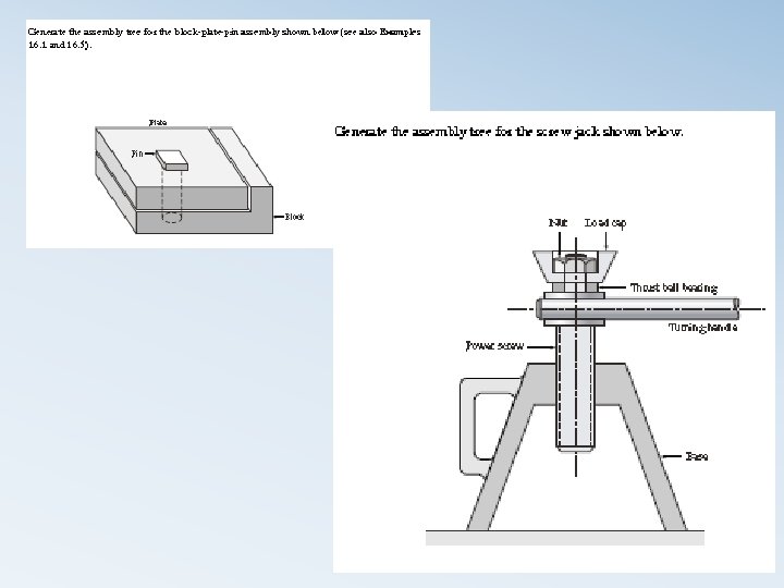
Problems
- Slides: 49