DRAWING ORTHOGRAPHIC PROJECTIONS 1 Draw border and title

DRAWING ORTHOGRAPHIC PROJECTIONS 1. Draw border and title block 2. Locate starting point to center drawing (use construction) 3. Construct front view and PROJECT lines across paper 4. Construct top view and PROJECT lines across paper

1. Draw ½” border 2. Draw a 1/2” title block 3. Add 2 LIGHT lettering guidelines, 1/16” from border lines 4. Add scale separator – Heavy Weight ½” 1/2” 1 ¾” LETTER the title block information: BPI-IOT ORTHO PROJ 1 17 OCT 08 LAST, F FULL SCALE

5. Measure the overall width and height of drawing space W H

HORIZONTAL STARTING POINT 1. Add width of front view to width of right view. 2. Add the space we will put between: 1. 5” 4” + 1. 5” = 7”

3. The remaining space is equal to W – 7” = ~3”. 4. Divide the remaining space by 2 to get horizontal pt. Horizontal Starting Point is 1. 5”

VERTICAL STARTING POINT 1. Add height of front view to height of top view. 2. Add the space we will put between: 1. 5” 2. 5” + 1. 5” = 5. 5”

3. The remaining space is equal to H – 5. 5” = ~1. 75”. 4. Divide the remaining space by 2 to get vertical pt. Vertical Starting Point is 7/8”

Technical Graphic Communication January 13, 2010 PREPARATION • Get a set of drafting tools: – T-Square – 1 Triangle – ~4” Tape – Ruler • Square and tape the back of the scales worksheet (horizontally with holes on top) IOT 2 -13 POLY ENGINEERING

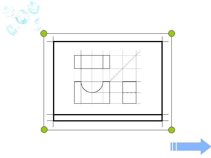
DRAWING ORTHOGRAPHIC PROJECTIONS 1. Locate the top-most, right-most intersection of front view construction lines. 2. Use a 45 -deg triangle and project a miter line. 3. Project lines down for. DO right view. NOT ERASE CONSTRUCTION LINES THEY FADE IN COMPARISON TO OBJECT LINES DARKEN what needs to be DARKENED

IOT – COMMUNICATION TECHNOLOGY *Holes go all the way through
- Slides: 11