Drainage of Irrigation Lands FAO 1996 Definitions Definitions


 • Mc. Math")


 of design • Surface drains should be designed to handle")

")
 1 2 3 4")
")


")


 Da Daily Time te consump Perio tive use d Total Consum ptive")

,")


 is a measure of")


- Slides: 128
Drainage of Irrigation Lands FAO, 1996 Definitions
Definitions • In many irrigation projects, crop yields are reduced due to waterlogging and salinization of the land. In some case, there is total loss of productions and therefore the land is abandoned.
Definitions • Ponding is the accumulation of excess water on the soil surface. • Waterlogging is the accumulation of excess water in the root zone of the soil.
Definitions
Definitions • Drainage is the removal of excess water and dissolved salts from the surface and subsurface of the land in order to enhance crop growth.
Drainage natural artificial
Definitions • A man-made drainage system is an artificial system of surface drains and/or subsurface drains, related structures, and pumps (if any) to remove excess water from an area.
Aims of Drainage • Drainage to Control Ponding • Drainage to Control Waterlogging • Drainage to Control Salinization
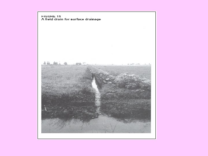
Drainage to Control Ponding • To remove ponding water from the surface of the land, surface drainage is used. Normally, this consists of digging shallow open drains (mostly) or pipe drain.
Drainage to Control Ponding • Surface drainage is the removal of excess water from the surface of the land by diverting it into improved natural or constructed drains, supplemented, when necessary, by the shaping and grading of the land surface towards such drains.
By shaping By grading
By pipe
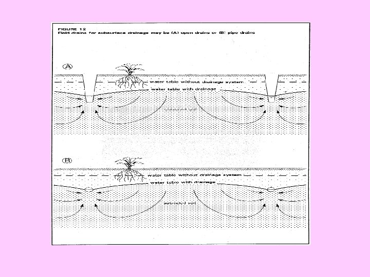
DRAINAGE TO CONTROL WATERLOGGING • To remove excess water from the root zone, subsurface drainage is used (Figure 6). This is done by digging open drains or installing pipes, at depths varying from 1 to 3 m.
Subsurface Drain-open drain
Subsurface Drain-pipe drain
Drainage to Control Salinization • To remove salts from the soil, more irrigation water is applied to the field than the crops require. This extra water infiltrates into the soil and percolates through the root zone. While the water is percolating, it dissolves the salts in the soil and removes them through the subsurface drains.
Drainage to Control Salinization
Drainage of Irrigation Lands Chapter 3 Drainage system
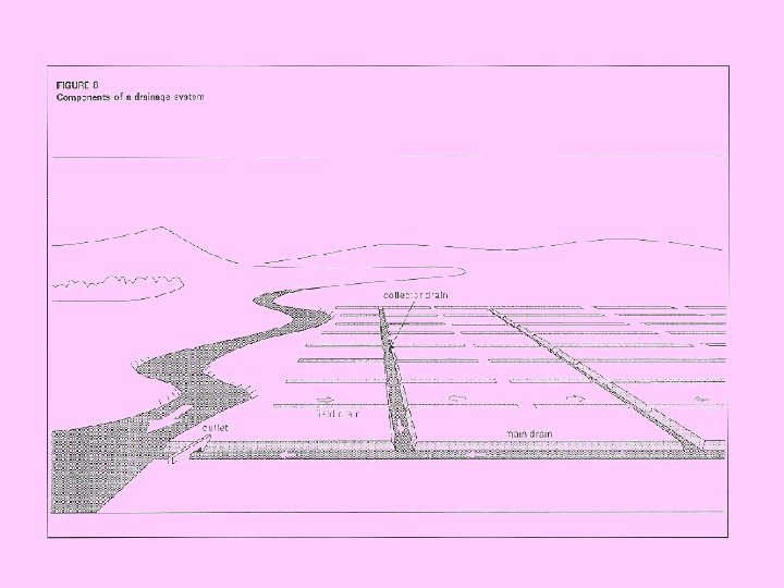
Components of a Drainage System Field drain Diversion Drain Collector Drainage system component Main Drain Outlet Interceptor Drain
Components of a Drainage System • A field drainage system, which prevents ponding water on the field and/or controls the water table. • A main drainage system, which conveys the water away from the farm. • An outlet, which is the point where the drainage water is led out of the area.
Components of a Drainage System • Collector drains can be either open drains or pipe drains. • interceptor drain: drains intercepting surface flow or groundwater flow from outside the area • The outlet is the terminal point of the entire drainage system, from where the drainage water is discharged into a river, a lake, or a sea.
Field Drainage System Surface Drainage System Pipe Drain Open Drain Sub Surface Drainage System Pipe Drain Open Drain
• The main drain is often a canalized stream (i. e. an improved natural stream), which runs through the lowest parts of the agricultural area (Figure 9).
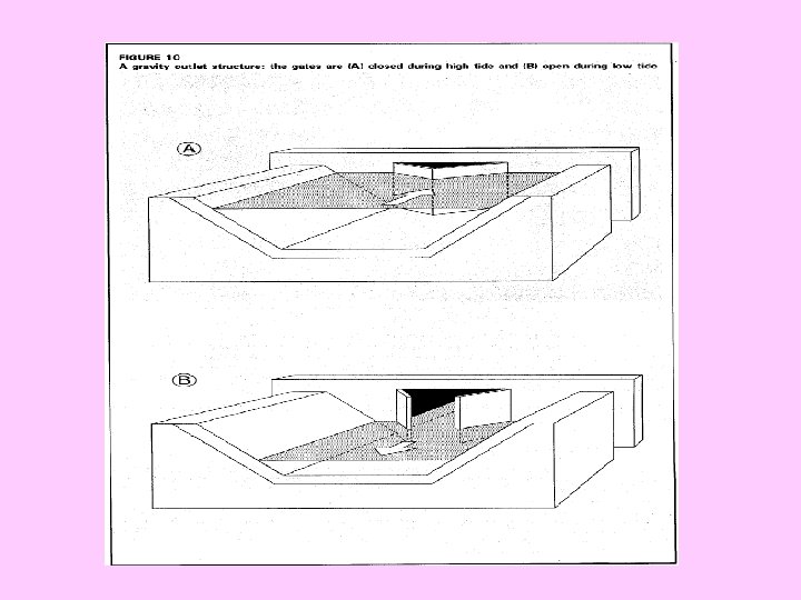
outlet • An outlet can be one of two kinds: a gravity outlet or a pumping station. A gravity outlet is a drainage structure in an area which has outside water levels that rise and fall. There, the drainage water can flow out when the outside water levels are low (Figure 10). In delta areas, drainage by gravity is only possible for a few hours a day when tides are low. In the upstream regions of a river, drainage by gravity might not be possible for several weeks, during periods when river levels are high.
Drainage System Surface Sub Surface
Components of Surface Drainage System • Open field drains (or on uncommon cases pipe drain) to collect the ponding water and divert it to the collector drain. • Land forming to enhance the flow of water towards the field drains.
Components of Surface Drainage System Field Drain Land Forming
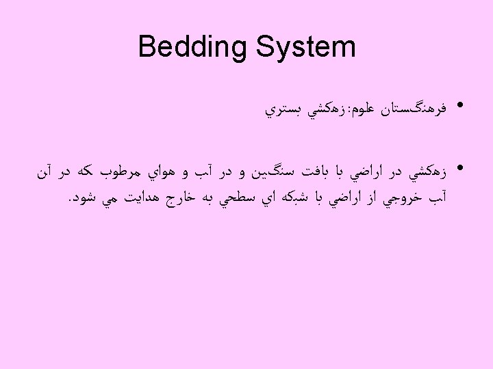
Land Forming Bedding Land grading Land planing
Bedding • Bedding is a surface drainage method achieved by ploughing land to form a series of low beds, separated by parallel field drains.
Bedding • The bedding system is normally used for grassland. In modern farming, bedding is not considered an acceptable drainage practice for row crops, because rows near the field drains will not drain satisfactorily. To overcome the disadvantages of the bedding system, the two other methods of land forming have been developed: land grading and land planning.
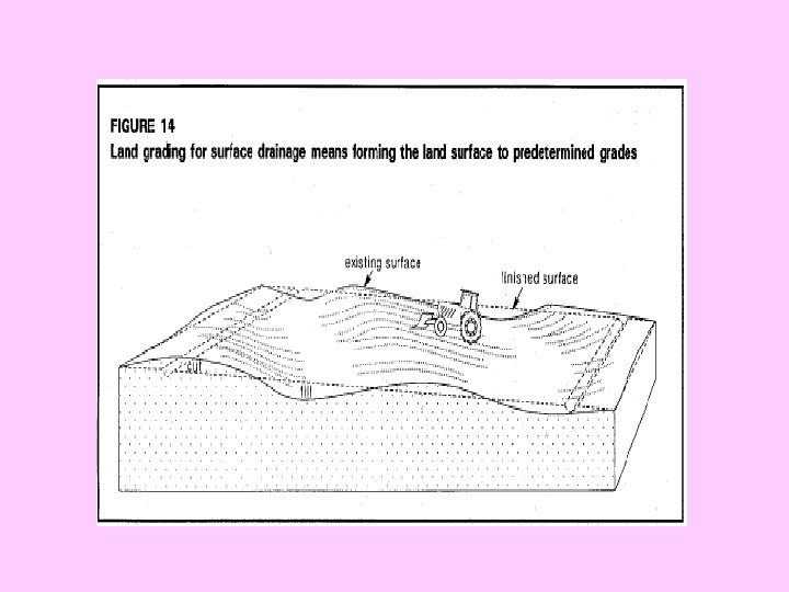
Land grading • Land grading for surface drainage consists of forming the land surface by cutting, filling and smoothing it to predetermined grades, so that each row or surface slopes to a field drain (Figure 14).
Advantages of Land grading method • Compared with bedding, land grading reduces the number of field drains, thus reducing the need for weed control and maintenance. Land grading also means that more land is available for use.
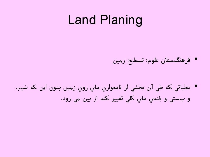
Land planing • Land planing is smoothing the land surface with a land plane to eliminate minor depressions and irregularities without changing the general topography.
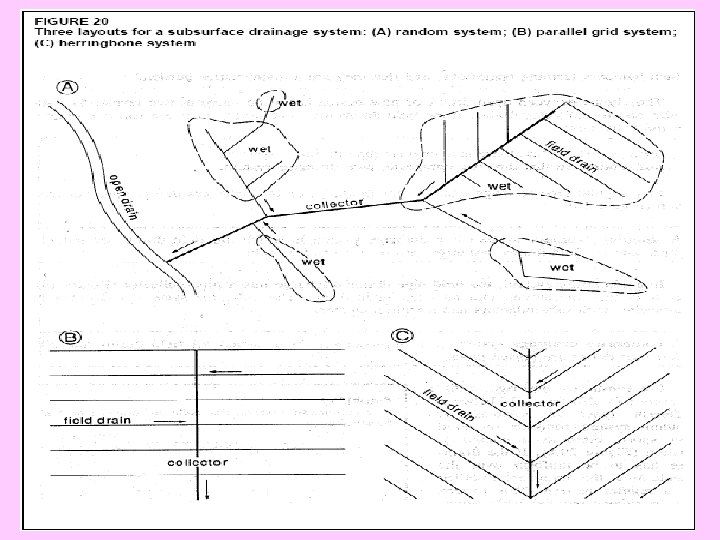
Surface Drainage System Layouts Random Field Drainage System Parallel Field Drainage System
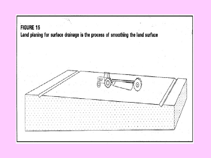
Random field drainage system • The random field drainage system connects the depressions by means of a field drain and evacuates the water into a collector drain (Figure 16). The system is often applied on land which does not require intensive farming operations (e. g. pasture land) or where mechanization is done with small equipment.
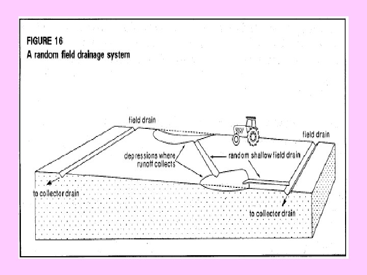
Parallel field drainage system • The parallel field drains collect the surface runoff and discharge it into the collector drain. The spacing between the field drains depends on the size of fields that can be prepared and harvested economically, on the tolerance of crops to ponding, and on the amount and costs of land forming. The system is suitable in flat areas with an irregular micro-topography and where farming operations require fields with regular shapes.
Subsurface drainage systems • A subsurface drainage system is a manmade system that induces excess water and dissolved salts to flow through the soil to pipes or open drains, from where it can be evacuated.
Subsurface drainage systems • If it is decided to install a subsurface drainage system, a choice has to be made between open drains or pipe drains. Open drains have the advantage that they can receive overland flow and can thus also serve as surface drainage. The disadvantages are the loss of land, the interference with the irrigation system, the splitting up of the land into small farm blocks, which hampers farming operations, and that they are a maintenance burden.
Subsurface drainage systems • The choice between open drains or pipe drains has to be made at two levels: for field drains and for collector drains. If the field drains are to be pipes, there are still two options for the collectors: • open drains, so that there is a singular pipe drainage system; • pipe drains, so that there is a composite pipe drainage system.
A singular drainagesystem is a drainage system in which the field drains are buried pipes and all field drains discharge into open collector drains.
A composite drainage system is a drainage system in which all field drains and all collector drains are buried pipes.
Combined Drainage System • Sometimes, combined surface and subsurface drainage systems are used. • Whether this is needed or not depends on a combination of factors: the intensity and duration of the rainfall, surface storage, the infiltration rate, the hydraulic conductivity and groundwater condition.
Example for combined system in arid and semi-arid region
Example for combined system in arid and semi-arid region • Areas with occasional high-intensity rainfall (say more than 50 mm/day), which causes water to pond at the soil surface, even when a subsurface drainage system has been installed.
Drainage of Irrigation Lands Chapter 4 Factors related to drainage
1 - Drainage Requirement • The drainage requirement is the amount of water that must be removed from an area within a certain period so as to avoid an unacceptable rise in the levels of the groundwater or surface water.
• To calculate the drainage requirement, an analysis has to be made of the overall water balance of the study area (Figure 22).
The main factors of drainage requirement Amount of Surface Runoff Fluctuating Water table
Surface Runoff • Surface flow must be considered in drainage analysis because this water must be carried away from agriculture lands. • Surface flow originates from precipitation and from irrigation waste.
Two methods of estimating surface runoff originate from precipitation (Storm flow) • Mc. Math method • SCS Method (Soil Conservation Service) It is suitable for Watersheds up to 800 ha size
Mc. Math Formula
Determining C
Return period (recurrence interval) of design • Surface drains should be designed to handle flows from 5 to 15 years storm frequencies. • In the special Condition ( for expensive structures) 25 year storm frequency should be used.
Intensity of precipitation in return period Where Pmax is the maximum percipitation in return period in inches tc is the time of concentration in hours
Time of concentration (tc)
SCS Methods (Figure 2 -10) 1 2 3 4
SCS (Figure 2 -11)
Fluctuating water table The main factors of drainage requirement Amount of Surface Runoff Fluctuating Water table
The Water Table • Below the water table, all the soil pores are filled with water. This is known as the saturated zone (Figure 23). Above the water table, there is a zone where the soil pores are filled partly with water and partly with air. This is the unsaturated zone. The unsaturated zone is very important for plant growth. This is the zone where roots take up water.
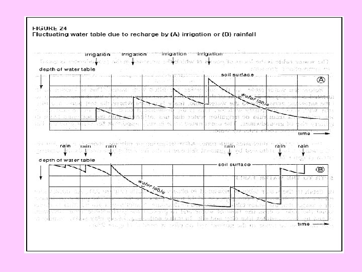
Water table • The water table fluctuates with time. After irrigation or rainfall, there is a sudden rise of the water table, followed by a gradual fall due to the flow of water towards the drainage system (Figure 24).
Variation of Water Table • For calculating water table level, in first stage, the designer must be estimated the volume of infiltration, holding capacity and Deep percolation.
Infiltration • Infiltration is the process of entry of the water into soil. • Soil texture and vegetation have major influence on the infiltration rate. • Infiltration rate depends on initial moisture content of soil, hydraulic conductivity, soil structure, presence of impeding soil layers in the profile, exchangeable cations, organic matter content, kind of clay and tendency to crust even in the same texture class.
Estimating infiltration based on irrigation • Cumulative infiltration also known as accumulated infiltration is the total quantity of water that enters the soil in a given time. • Cumulative infiltration is represented as:
Cumulative infiltration
Problem • Calculate the amount of infiltrated water in the following condition: • Time of irrigation: 5 hours • Cumulative infiltration based on Ans. : t=300 minute→ D= 27. 8 cm or 278 mm
Estimating infiltration based on precipitation (SCS Method)
Problem Calculate deep percolation form the root zone in the following condition: • Time of irrigation: 3 hours • Cumulative infiltration based on • Root zone 60 cm • Initial moisture equal m. PWP Soil Depth cm m. FC % m. PWP % b g/cm 3 0 -15 26. 2 10 1. 5 15 -30 25. 5 10. 5 1. 52 30 -45 24. 3 9. 6 1. 56 45 -60 25. 6 10. 2 1. 65
Moisture holding capacity • Moisture holding capacity is the physical property of the soil that determines the maximum amount of water held in the root zone under free drainage conditions. • When the available moisture in the critical quarter is completely exhausted, the plant will be unable to extract sufficient moisture from the remaining quarters to maintain rapid crop growth.
Estimating of Moisture holding capacity based on readily available water Critical quarter
Another Example for critical quarter Critical quarter
Estimating Deep percolation
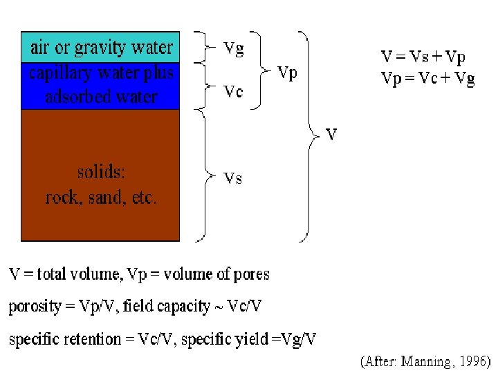
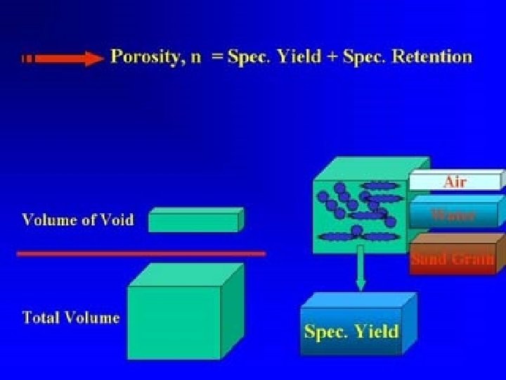
Specific yield Saturation Point Field Capacity Permanent Wilting Point Volume of Soil Solid Air and Water Available Water Deep percolation Total Porosity Effective Porosity
Specific Yield • Specific yield may be defined as the volume of water released from a known volume of saturated soil under the force of gravity and inherent soil tension.
Specific Yield Sy min ma x 610 16 -18 K Soil Text ure heavy light Note: When the specific yield is less than 3 percent, drainage become difficult and expensive.
Estimating Specific yield by Hydraulic Conductivity
Estimating of variation of water table • The variation of water table is calculated as follow: h 2= final level in meter h 1=initial value in meter Dp=deep percolation in mm S= Specific yield in percent
Problem • Find the variation of water table in the following condition: Root zone depth: 60 cm Infiltration: 215 mm Quarte Soil r texture FC PWP 1 Loam 31 14 2 Clay Loam 37 18 3 Clay Loam 37 18 4
Problem (continue) Da Daily Time te consump Perio tive use d Total Consum ptive (Day) (mm/per iod Remai ning RAW mm Infiltra tion mm Total Moist ure mm 0 215 Endi ng RA W mm D p m m R D H m p m m mm H m 910 2 1230 4. 5 90 180 -52. 5 215 162. 5 127. 35 90 -55 -. 55 2. 67 5 5 210 5 40 180 -52. 5 215 162. 5 127. 35 40 -5 -. 05 2. 72 5 5 3 -9 7 30 150 -22. 5 215 192. 5 127. 65 30 35 5 . 35 2. 37 5 20 140 -12. 5 215 202. 5 127. 75 20 35 5 . 55 1. 82 5 329 127. 8 5 7. 5 0 87. 0. 8 2. 12 5 75 5
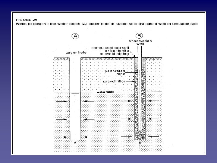
Measurement of water table The depth to the water table is measured in observation wells (Figure 25). An observation well is a small-diameter plastic pipe (> Ø 12 mm), placed in the soil. The pipe is perforated over a length that the water table is expected to fluctuate. Sometimes a gravel filter is placed around the pipe to ease the flow of water and to prevent the perforations from becoming clogged by fine particles like clay and silt. In stable soils (e. g. heavy clay soils), simply an auger hole can be made in the ground and no pipe is needed (Figure 25 A).
Measurement of water table 1. Wetted tape method A steel tape (calibrated in millimeters), with a weight attached to it, is lowered into the pipe or auger hole to below the water level. The lowered length of tape from the reference point (e. g. the top of the pipe) is noted. The tape is then pulled up and the length of its wetted part is measured.
Measurement of water table 2. Mechanical sounder This consists of a small steel or copper tube (10 to 20 mm in diameter and 50 to 70 mm long), which is closed at its upper end, open at its bottom end, and connected to a calibrated steel tape. When lowered into the pipe, it produces a characteristic plopping sound upon hitting the water. The depth to the water level can be read directly from the steel tape.
Measurement of water table 3. With an electric water-level indicator This consists of a double electric wire with electrodes at their lower ends. The upper ends of the wire are connected to a battery and an indicator device (lamp, amp meter, sounder). When the wire is lowered into the pipe and the electrodes touch the water, the electrical circuit closes, which is shown by the indicator.
Measurement of water table 4. Floating level indicator or recorder This consists of a float (60 to 150 mm in diameter) and a counterweight attached to an indicator or recorder. Recorders can generally be set for different lengths of observation period. They require relatively large pipes. The water levels are either drawn on a rotating drum or punched into a paper tape.
Measurement of water table 5. Electronic water-level logger The pressure recordings are controlled by a microcomputer and stored in an internal, removable memory block. The recorded data are read by a personal computer. Pressure loggers have a small diameter (20 to 30 mm) and are thus well suited for measurements in small-diameter pipes.
MEASURING GROUNDWATER SALINITY The EC expresses the total concentration of soluble salts in the groundwater, but gives no information on the types of salts. These may be calcium, magnesium, sodium, potassium, carbonate, bicarbonate, chloride, sulphate, and nitrate, and need to be determined in the laboratory. Since these chemical analyses are costly, not all the observation points need be sampled for detailed analysis. A selection of sites should be made, based on the results of the EC-measurements.
Drainage Coefficient Drainage coefficients are used in determining the design capacity of a system. The drainage coefficient is that rate of water removal to obtain the desired protection of crops from excess surface and subsurface water.
Drainage Coefficient For subsurface drainage, the coefficient is usually expressed as a depth of water to be removed over a safe period of time, usually 24 hours. For surface drainage, the coefficient may be expressed as a flow rate per unit area.
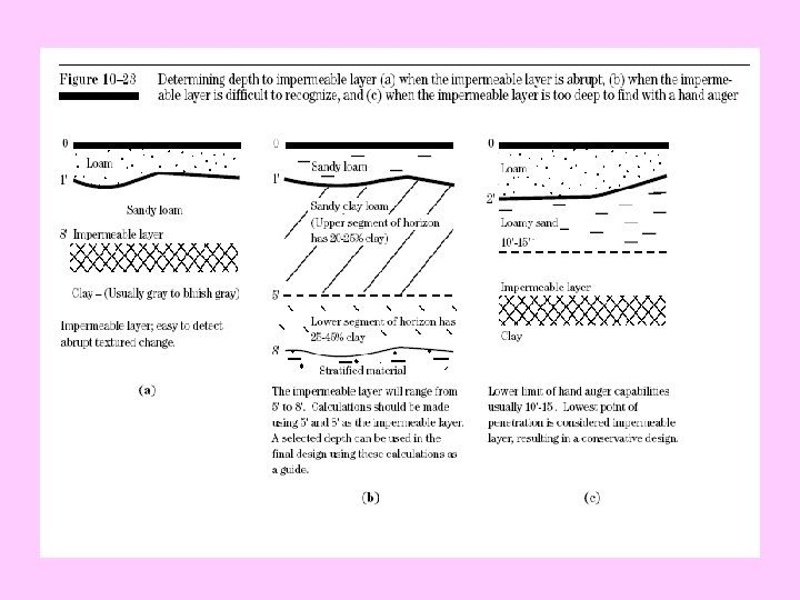
Determine the depth to the impermeable layer In the field, the depth to the impermeable layer (horizon) is usually determined by boring holes and observing the textural changes that occur between horizons. Generally, an impermeable layer is considered to be where the permeability is in the order of one tenth of the layer above. In many cases the depth to the impermeable layer cannot be determined without a drill rig. As a result, holes are bored 10 to 15 feet deep with hand augers. If an impermeable layer is not found, it is considered to be the deepest point of penetration. This results in a conservative design, which will be adequate (fig. 10– 23).
HYDRAULIC CONDUCTIVITY The hydraulic conductivity (also known as the K-value) is a measure of the water-transmitting capacity of soils. There are big differences between the Kvalues of soil types, mainly depending on their texture (Table 2).
HYDRAULIC CONDUCTIVITY
Methods of Hydraulic Conductivity measurement Libratory methods Field methods
Field methods Above the Water Table Below the Water Table
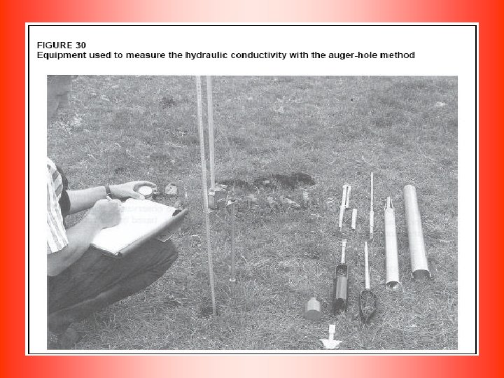
Auger Hole Test Below the W. T. Well Permeameter Method Piezometer Test
Well Permeameter Method The Well Permeameter Method is a field test for determining the permeability of soil in place is used by the Bureau of Reclamation (17). This method, consisting of measuring the rate at which water flows outward from an uncased well under constant head, is particularly useful for estimating the need for lining an irrigation canal before construction. The apparatus required for the test and the procedure are described in the Bureau's Earth Manual
Impermeable Layer