DR MANU JOSEPH CT BASICS History Basic Principle

DR MANU JOSEPH

CT BASICS History Basic Principle Structural Components Core physics : Image reconstruction and display Brief review: Image quality-Noise, Resolution Dose and Patient exposure parameters CT Artifacts

XRAYS WERE A DISCOVERY…. …. CT WAS AN INVENTION !

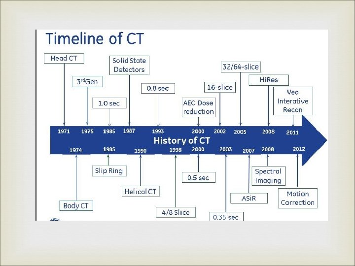
MILESTONES IN CT DEVELOPMENT YEAR EVENTS 1969 G. N. Hounsfield developed first clinically useful CT head scanner 1971 First clinically useful CT head scanner was installed at Atkinson. Morley Hospital (England) 1972 First paper on CT presented to British Institute of Radiology by Hounsfield and Dr. Ambrose 1974 Dr. Ledley introduced the whole body CT scanner (ACTA scanner) 1979 G. N. Hounsfield shared the Nobel Prize with Allan Mac. Leod Cormack

SIR GODFREY HOUNSFIELD

BASIC PRINCIPLE Z axis The internal structure of an object can be reconstructed from multiple projections of that object.

STRUCTURAL COMPONENTS Basic components and Scanner generations Individual components

SCANNER COMPONENTS Xray Tube. Collimators and Filters. Detectors : v Xenon gas ionisation chamber. v Scintillation detectors

BASIC COMPONENTS :

T GANTRY INTERNAL COMPONENTS

CT XRAY TUBE Arranged with Anode-Cathode axis parallel to axis of rotation of gantry. Minimizes the Anode heel effect. Capable of prolonged exposure times (>90 s) at high ampearage(200 m. A and 120 k. V). Has high heat loading as well as Heat dissipation capabilities. Heat exchangers to cool the oil, and air is maintained at low temp. Two Focal spot sizes : v Smallest being 0. 6 mm.

COLLIMATORS : Mounted on the Xray tube. Width : 50 cm at the axis of rotation – sufficient to cover the full cross-section of patient. Along z axis : Variable v In single slice scanners defines the slice thickness. v Fixed width settings avaliable 1 to 10 mm. v Post patient collimators : to reduce scatter radiation.

FILTERS : May be used to filter out low energy photons to make the beam uniform(Minimize beam hardening) BOW TIE Filters : Low tissue thickness in beam path at periphery of patient. Noise levels are poorly matched being max at centre Also dose at the periphery and on skin is unneccesarily high. Special filters which are thin at centre and thick at periphery are used “ BOW TIE “ Filters.

DETECTORS : IDEAL DETECTOR Charecteristics : v v Small in size - For better spatial resolution Have high detection efficiency. Have a fast response with negligible afterglow. Have a wide dynamic range – must respond to a wide range of Xray beam intensity. v Have a stable noise free response.
 when")
SCINTILLATION DETECTORS Solid state devices made of materials which will produce light (scintillate) when ionising radiation reacts with them. Made up of two components : v Polished Scintillation crystal. v Light detector – Converts the light output to a electrical signal. Electrical signal output of detectors is proportional to the incident photon. Overall efficiency is 80 %.

THE HISTORIC EMI SCANNER : Typical 1 st generation scanner. Designed specifically for imaging of brain. Head was enclosed in a water bath between Xray tube above and Detectors below. Oil cooled stationary anode tube of focal spot size 2. 25 x 12 mm used. Xray beam was heavily filtered with a half-value layer of 6 mm of aluminium. Pair of slit like collimators, one near Xray tube and other near detectors. Two Detectors side-by-side : Na. I Scintillation crystals + Photomultiplier tubes. Time : 5 min for a pair of slices 25 -30 min for a complete scan.

SCANNER GENERATIONS Represent gradual evolution of CT technology. Refers to the betterment of the mechanical construction of the scanner. Main aim of improvisation was Reducing scan time. Four generations are known with an arbitrary 5 th generation/Recent advancements.

1 st. GENERATION/TRANSLATE-ROTATE SCANNER Xray tube – Emitting a pencil like Xray beam. Single detector(1 detector per tomographic section). Both fixed on a rigid Gantry, and could not move independent of each other. Had both linear motion (Translate) and rotary motion (Rotate) TIME : 5 min per tomographic slice 25 – 30 min per brain scan.

1 st. GENERATION/TRANSLATE-ROTATE SCANNER

2 nd GENERATION/TRANSLATE-ROTATE SCANNER Xray tube – Fan shaped Xray beam Multiple detectors (as many as 30 detectors ) Extent of translation movements required are reduced. Rotation angle per aquisition is increased – depending upon the no. of detectors (About 30 degrees ) TIME : 10 – 90 sec per tomographic section.

2 nd GENERATION/TRANSLATE-ROTATE SCANNER

3 rd GENERATION/ROTATE-ROTATE SCANNER Xray tube – Fan shaped X-ray beam – wide enough to cover the entire pt cross section. Detectors – Large no. of small detectors arranged in an arc to cover the complete cross section of the patient. Both the tube and detectors rotate about the patient in a circle with centre coinciding the patients centre. Need for linear translation eliminated. Allowed continuous data collection through 360 degree rotation. TIME : 4. 9 sec per scan

3 rd GENERATION/ROTATE-ROTATE SCANNER

4 th GENERATION /ROTATE – FIXED SCANNERS Xray tube – Fan shaped Xray beam. Detectors – Form a stationary ring outside the path of movement of the rotating Xray tube. Overcame problems of detector stability and made reconstruction simpler.

4 th GENERATION /ROTATE – FIXED SCANNERS

5 th GENERATION SCANNER / ELECTRON BEAM SCANNER Electron gun with focussing and deflecting coils. High voltage tungsten target ring covering a 210 degree arc below the patient. Xrays are produced and after passing through patient and collimation, are detected on a 216 degree arc of detectors above. No mechanical moving parts. TIME – 50 ms for sweeping the electron beam across the arc. - Used predominantly for cardiac imaging.

5 th GENERATION SCANNER / ELECTRON BEAM SCANNER

RECENT ADVANCEMENTS MAYO CLINIC’S DYNAMIC SPATIAL RECONSTRUCTER : v 28 Xray tubes positioned along a semicircular gantry. v Aligned with 28 light amplifiers and TV cameras behind a single curved fluorescent screen behind the pt. v Entire assembly rotates at 15 revolutions/min. v TIME : 1 image in 15 ms. v High cost , mechanical motion not eliminated.

HELICAL SCANNING : Also known as Volume scan/ Spiral scan. Evolved by a mechanistic breakthrough technology “Slipring “ in the construction of the scanner. Stationary metal ring mounted on the gantry. It continously maintains contact with the rotating gantry, Supplying power to the Xray tube and also receiving signals from the detectors. Thus continuous 360 degree rotation of gantry is possible without an intervening reverse rotation and without entangling of rigid wiring system.

HELICAL SCANNING : SCANNING TERMS : Acquisition • The process by which a single , continuous volume of CT data is acquired without a pause. Revolution • One complete 360 degree rotation of the Xray tube around the patient or object of interest. Pitch factor Interpolation • The distance the couch or patient travels through the gantry during one 360 degree beam rotation. • A unitless parameter by which he pitch can be designated, defined as the pitch (mm) divided by the collimated slice thickness (mm). • A mathematical technique used to estimate the value of a function from values on either side of it.

ADVANTAGES OF HELICAL CT : Minimized motion artefacts : As a result of faster scan times. Decreased misregistration between adjacent slices. Reduced patient dose : Increasing pitch to 1. 5 from 1 leads to a 33 % decrease in patient dose. However this occurs at the cost of decreased spatial resolution. Improved resolution on along z axis. Enhanced multiplanar or three dimensional rendering :

MULTIDETECTOR CT: Evolved for the need of 3 D imaging and Faster scan acquisition. 3 D reconstruction requires isotropy I; e Voxel size must be equal in all 3 dimensions. Also the 3 D resolution is better, when the voxel size is as smaller as possible.

MULTIDETECTOR CT : Theorotically single slice helical scanners have the capability of collimating down to a slice width of 1 mm. Thus it has 3 D imaging capability but it is restricted by the scanning time. Total scanning time is limited to 90 sec due to Xray tube limitations. Thus with 1 sec rotation speed volume to be imaged will be restricted to 90 mm at max resolution.

MULTIDETECTOR CT : Two new modifications are made to the existing system: v Instead of a fan beam which is flat along the z axis, a divergence is added to the fan beam along the z axis creating a cone shaped beam. v Instead of a single row of detectors along the z axis, multiple rows of detectors are used. These modifications overcome the shortcomings of the single slice helical detector for 3 D imaging.

MULTIDETECTOR CT :

MULTIDETECTOR CT : DETECTOR DESIGN : Equal width detector : v Detectors of equal width are stacked back to back along the z axis. Variable width detector : v Combines fewer detectors of variable widths and a postpatient collimator to define slice width.

1 st GEN : Pencil beam, Single detector. 2 nd GEN : Fan beam, Single row array of detectors. 3 rd GEN : Wide Fan beam, wide single row detectors to eliminate translation. 4 th GEN : Wide fan beam, Complete circular single row of detectors to eliminate one rotation component. HELICAL SCANNING : Continuous 360 degree rotation and Data acquisition possible with Sliprings. MULTIDETECTOR CT : Cone beam, Multiple row array of detectors, with Slipring. ELECTRON BEAM SCANNER : Staionary source, Stationary detectors, Electron gun and focussers used.

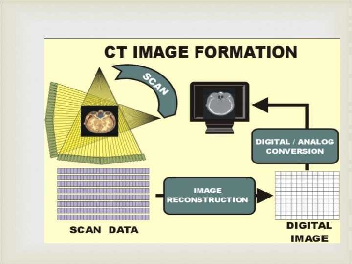
CT NUMBER / HOUNSFIELD UNITS : From all collected data, computer calculates the linear attenuation coefficient for each pixel. This value is converted in a new number, THE CT NUMBER = K x (uo – uw) u w K = Constant (1000 in currently avaliable units) U 0 = Pixel linear attenuation coefficient Uw = Water linear attenuation coefficient.

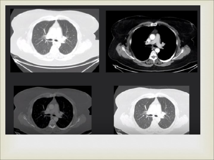
CT NUMBERS / HOUNSFIELD UNITS Thus the range CT values for common entities is : TISSUE RANGE OF CT NUMBERS Bone 500 – 1500 Muscle 40 – 60 Brain – Grey matter 35 – 45 Brain – White matter 20 – 30 Fat - 60 to – 150 Lung - 300 to - 800 The original EMI machine used a K constant value as 500.

CONCEPT OF WINDOWING CT image will have pixels with CT values ranging from – 1000 to + 1000. If all these are displayed by distinct graded shades of grey, it will result in the image appearing too flat due to the limited ability of human eye to distinguish the shades. Hence windowing is applied in digital imaging to bring out the most relevant detail in the image.

CONCEPT OF WINDOWING A CT number is selected – which is about the average CT number of the body tissue being examined. A range of CT numbers is then selected –appropriate for that tissue which is then distributed into two halves on either side of the above selected CT number. The range of CT values is known as Window Width. The previously selected CT number now comes to lie in the centre of the window width and is known as Window Level.
 : PRESET WL")
PRESET WL AND WW ON OUR GE WORKSTATION (AW VOLUMESHARE 2) : PRESET WL WW ACTUAL RANGE Head 35 100 - 65 Abdomen 40 400 - 360 to + 440 Lung - 700 1000 - 1700 to + 300 Vertebrae 350 2000 - 1650 to + 2350 Mediastinum 40 350 - 310 to + 390 Spine 35 300 - 265 to + 335 to + 135
. v")
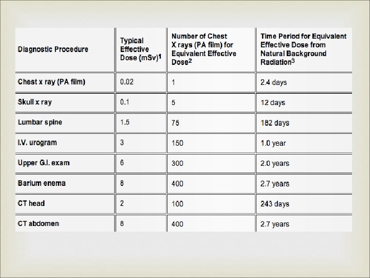
XRAY DOSE IN CT : Dosimetry parameters : v CT Dose Index (CTDI). v Dose-Length Product (DLP). v Effective dose. Factors affecting patient dose.
∙dz T Dose at position z, D(z),")
DOSIMETRY PARAMETERS : CTDI : CTDI = ∫D(z)∙dz T Dose at position z, D(z), is integrated over the complete dose profile and divided by the nominal slice width T. There are internationally accepted standards for CTDI that involve measurement in cylindrical perspex phantoms.

FACTORS AFFECTING PATIENT DOSE : k. V : v Commonly set to 120 k. V. v Increases dose exposure. m. A : v Constant m. A technique. v m. A modulation technique : 10 – 40 % dose reduction is possible. Helical or Axial Acquisition : v Slight greater in helical due to small amount of overscanning at start and end.

FACTORS AFFECTING PATIENT DOSE : Pitch : Inversely proportional to pitch. Use of pitch 1. 5 rather than 1. 0 leads to a 33 % dose reduction.

What we see

CT ARTIFACTS

CT ARTEFACTS : Refers to any systematic discrepancy between the CT numbers in the reconstructed image and the true attenuation coefficient of the object. CT images are inherently more prone to artifacts than conventional techniques because the image is reconstructed based on about a million of independent detector readings. The reconstruction technique assumes that all the measurements are accurate, thus any error in measurement is reflected as an artefact.

CLASSIFICATION OF CT ARTIFACTS : Based on Appearance : v Streaking : Due to an inconsistency in a single measurement. v Shading : Due to a group of channels or views deviating gradually from the true measurement. v Rings : Due to errors in individual detector calibration. v Distortion : Due to helical reconstruction.

CLASSIFICATION OF CT ARTIFACTS : Based on Origin : v Physics based artifacts : Result from physical processes involved in the acquisition of CT data. v Patient based artifacts : Caused by such factors as patient movement, or the presence of metallic materials in or on the pt. v Scanner based artifacts : Result from imperfections in scanner function. v Helical and Multisection artifacts : Produced by the image reconstruction process.

CT ARTIFACTS : PROTOCOL OF DISCUSSION : Mechanism of generation. Inbuilt Minimizing techniques. Techniques for avoidance by operator.

PHYSICS BASED ARTIFACTS : Beam hardening and resultant artifacts. Partial volume effect. Photon starvation Undersampling

BEAM HARDENING AND RESULTANT ARTIFACTS : Xray beam is composed of individual photons with a wide range of energies. As the beam passes through an object it becomes HARDER , its mean energy increases , because lower energy photons are absorbed more rapidly than higher energy photons. This can result in two types of artifacts : v Cupping artifacts v Appearance of dark bands / streaks between dense objects in the image.

BEAM HARDENING EFFECT : CUPPING ARTIFACTS : Xrays passing through middle portion of a uniform cylindrical phantom are hardened more than those at periphery because it passes through more material. As the beam becomes harder the rate at which it is attenuated decreases. Beam reaching the detector is more intense than if it had not been hardened. Resultant attenuation profile differs from the ideal profile that would be obtained without beam hardeneing.

BEAM HARDENING EFFECT : CUPPING ARTIFACTS :

BEAM HARDENING EFFECT : STREAK AND DARK BANDS : In very heterogenous cross sections , dark bands or streaks can appear between two dense objects in an image. Occur because the portion of beam that passes through one of the objects at certain tube positions is hardened less than when it passes through both objects at other tube positions. Can occur both in bony regions of body and in scans where a contrast medium is used.

BEAM HARDENING EFFECT : STREAK AND DARK BANDS :

BEAM HARDENING EFFECT : BUILT-IN MINIMIZING FEATURES : Filtration : v A flat piece of attenuating material, usually metal, is used to pre-harden the beam by filtering out lower energy components before it passes through pt. v Bow-tie filter can also be used.

BEAM HARDENING EFFECT : BUILT-IN MINIMIZING FEATURES : Calibration correction : v Scanners are calibrated using phantoms in a range of sizes. . v Thus detectors are calibrated with compensation tailored for beam hardening effects of different bodyparts of pt. v Since pt anatomy never exactly matches a cylindrical calibration phantom, there may always be a slight residal cupping artifact or a slight “capping” artifact with higher central CT value due to overcorrection.

BEAM HARDENING EFFECT : BUILT-IN MINIMIZING FEATURES : CALIBRATION CORRECTION :

BEAM HARDENING EFFECT : BUILT-IN MINIMIZING FEATURES : Beam hardening correction software : v Iterative correction algorithm applied when images of bony regions are being reconstructed. v Helps minimizing blurring of bone-soft tissue interface in brain scans. v Reduces appearance of dark bands in nonhomogenous cross sections.

BEAM HARDENING EFFECT : BUILT-IN MINIMIZING FEATURES :

BEAM HARDENING EFFECT : AVOIDANCE BY OPERATOR : Using proper patient positioning and tilting of gantry. Select appropriate FOV. Using appropriate bow-tie filters.

PARTIAL VOLUMING : Not an artifact in itself but a limitation of image reconstruction. Refers to the smallest unit of spatial resolution of a CT machine being a single voxel. Thus all the components present within a voxel will influence its final attenuation coefficient or CT number. Thus the appearance of an entire voxel may be adversely affected due to the presence in it of a small part of a high or low attenuation or object.

PARTIAL VOLUMING : MAY LEAD TO ARTIFACT GENERATION : Artifact may occur when a dense object lying offcentre protrudes partly into the width of Xray beam. Inconsistencies between the views cause shading artefacts to appear in the image.

PARTIAL VOLUMING : AVOIDANCE : Using a thin acquisition section width – especially in imaging a body part whose anatomy is rapidly changing in the z axis such as the posterior fossa.

PHOTON STARVATION : Occurs in highly attenuating areas such as the shoulders. Xray beam travelling horizontally is greatly attenuated and insufficient no. of photons reach the detector. Very noisy projections are produced at these tube angulations. Reconstruction process has the effect of greatly magnifying the noise, resulting in horizontal streaks in the image.

PHOTON STARVATION :

PHOTON STARVATION : IN-BUILT MINIMIZING TECHNIQUES : Automatic tube current modulation : v Tube current is automatically varied during the course of each rotation, this process is known as Milliamperage modulation. v This allows sufficient photons to pass through the widest parts of the pt. without unneccesary dose to narrower parts.

PHOTON STARVATION : IN-BUILT MINIMIZING TECHNIQUES : Adoptive filtration : v Software correction which smoothens the attenuation profile in areas of high attenuation before the image is reconstructed.

PHOTON STARVATION : IN-BUILT MINIMIZING TECHNIQUES : Multidimensional adaptive filtration : v Being developed for use on multisection scanners. v For the projection data that exceeds a selected attenuation threshold, smoothing is carried out between adjacent in-plane detectors and between successive projection angles. v Streaking is reduced while maintaining spatial resolution.

PHOTON STARVATION : USE OF MULTIDIMENSIONAL ADAPTIVE FILTRATION :

UNDERSAMPLING : The number of projections used to reconstruct a CT image is one of the determining factors in image quality. Too large an interval between projections (ie undersampling ) results in misregistration of information relating to sharp edges and small objects. This leads to VEIW ALIASING , where fine stripes appear to be radiating from the edge of, but at a distance from a dense structure. Stripes appearing close to the structute are called RAY ALIASING and is caused by undersampling within a projection.

UNDERSAMPLING : AVOIDANCE : Must be avoided where resolution of fine detail is important. VIEW ALIASING – minimized by acquiring largest possible number of projections per rotation. which may be done by a slow rotating speed. RAY ALIASING – minimized by using specialized high resolution techniques, such as Quarter detector shift, or Flying focal spot which increase the number of samples within a projection.

PATIENT BASED ARTIFACTS : Metal artifacts Motion artifacts Incomplete projection.

METAL ARTIFACTS : Presence of metal objects in scan field leads to severe streaking artefacts. They occur because the density of metal is beyond the normal range that can be handled by the computer, resulting in incomplete attenuation profiles. Additional artefacts due to beam hardening, partial voluming and aliasing compound the problem.

METAL ARTEFACTS : AVOIDANCE : Ask patients to remove all metal objects and jewellry before scanning. For nonremovable items, it is sometimes possible using gantry angulation to exclude the metal inserts from scans of nearby anatomy. When absolutely impossible to eliminate them, v Using high k. Vp may help penetrate some objects. v Using thin sections will reduce contribution due to partial volume artifacts.

METAL ARTIFACTS : IN-BUILT MINIMIZING TECHNIQUES : Special software corrections apply interpolation techniques to substitute the overrange values in attenuation profiles. Usefulness is limited because, although streaking distant from the metal implant is reduced, there still remains a loss of detail around the metal-tissue interface, which is often the main area of diagnostic interest. Beam hardening correction software must also be applied when scanning metal objects to minimize additional artifacts.

MOTION ARTIFACTS : Patient motion causes misregistration artifacts, which appear as shading/streaking in the image.

MOTION ARTIFACTS : IN-BUILT MINIMIZING TECHNIQUES : OVERSCAN AND UNDERSCAN MODES : v Maximum discrepancy in detector readings occurs between veiws obtained towards the beggining and end of a 360 degree rotation. v In overscan mode an extra 10 degree is added to standard 360 degree rotation, which helps reduce artifacts. v Underscan mode can also reduce artifacts but at the expense of poorer resolution.

MOTION ARTIFACTS : IN-BUILT MINIMIZING TECHNIQUES : . Software correction : v Automatic applying of reduced weighting to the beginning and end views to supress their contribution to the final image. v Additional specialised motion correction is also avaliable.

MOTION ARTIFACTS : IN-BUILT MINIMIZING TECHNIQUES : Cardiac gating : v Images are produced by using data from just a fraction of the cardiac cycle when there is least cardiac motion. v Achieved by combining ECG gating techniques.

MOTION ARTIFACTS : AVOIDANCE BY OPERATOR : Use of positioning aids to prevent voluntary movement. Sedation. Shortest possible scan times. Breath hold. Start and end position of tube is aligned with the primary direction of motion because sensitivity of an image to motion artifacts depends upon orientation of motion. For eg vertically above or below for a chest scan.

INCOMPLETE PROJECTION : If any portion of the patient lies outside the scan FOV the computer will have incomplete information relating to this portion and streaking or shading artifacts will be generated. This will also occur of object not to be scanned lies close to pt and interferes with xray beam transmission. Eg Pt scanned with arms down instead of being raised out of the way of scan. Blocking of reference channels at the sides of detector array may also interfere with data normalisation and cause streaking artefacts.

INCOMPLETE PROJECTION : AVOIDANCE : Position the pt properly. Some machines monitor the reference data channels for inconsistencies and avoid using reference data that appears suspicious.

SCANNER BASED ARTIFACT : RING ARTIFACT : If one of the detectors is out of calibration on a third-generation (rotating x-ray tube and detector assembly) scanner, the detector will give a consistently erroneous reading at each angular position, resulting in a circular artifact. AVOIDANCE : Detector recalibration v Repai services. v Selecting the correct FOV and using calibration data that fits more closely to pt anatomy.

HELICAL ARTIFACTS IN SINGLE SECTION SCANNING : In general, the same artifacts are seen in helical scanning as in sequential scanning. However, there additional artifacts that can occur in helical scanning due to the helical interpolation and reconstruction process. The artifacts occur when anatomic structures change rapidly in the z direction (eg, at the top of the skull) and are worse for higher pitches. If a helical scan is performed of a coneshaped phantom lying along the z axis of the scanner, the resultant axial images should appear circular. In fact, their shape is distorted because of the weighting function used in the helical interpolation algorithm.

HELICAL ARTIFACTS IN SINGLE SECTION SCANNING : To keep helical artifacts to a minimum, steps must be taken to reduce the effects of variation along the z axis. This means using, where possible, a low pitch. a 180° rather than 360° helical interpolator if there is a choice thin acquisition sections rather than thick. Sometimes, it is still preferable to use axial rather than helical imaging to avoid helical artifacts (eg, in brain scanning)

HELICAL ARTIFACTS IN MULTISECTION SCANNING : The helical interpolation process leads to a more complicated form of axial image distortion on multisection scanners than is seen on single-section scanners. The typical windmill-like appearance of such artifacts is due to the fact that several rows of detectors intersect the plane of reconstruction during the course of each rotation. As helical pitch increases, the number of detector rows intersecting the image plane per rotation increases and the number of “vanes” in the windmill artifact increases.

CONE BEAM EFFECT : As the number of sections acquired per rotation increases, a wider collimation is required and the x-ray beam becomes cone-shaped rather than fanshaped. As the tube and detectors rotate around the patient (in a plane perpendicular to the diagram), the data collected by each detector correspond to a volume contained between two cones, instead of the ideal flat plane. This leads to artifacts similar to those caused by partial volume around off-axis objects. The artifacts are more pronounced for the outer detector rows than for the inner ones , where the data collected correspond more closely to a plane.

CONE BEAM EFFECT :

- Slides: 104