Dr DYPIEMR AKURDI Mr Siddharth Shete Syllabus Part

Dr. DYPIEMR, AKURDI Mr. Siddharth Shete

Syllabus Part A: Mechanical Elements Function, sketch, description and uses of shaft, axle, key (parallel key), coupling, (rigid flange), bearing (ball), clutch (single plate clutch), brake Part B: Power transmission devices Construction, working, comparison and applications of: Belt drive (flat and V-belt), chain drive and spur gear drive arranged with simple gear train.

Part A Mechanical Elements Syllabus Function, sketch, description and uses of shaft, axle, key (parallel key), coupling, (rigid flange), bearing (ball), clutch (single plate clutch), brake
 Machine (arrangement of elements) Output (prescribed task)")
Introduction to machine Input (source of energy) Machine (arrangement of elements) Output (prescribed task) Ø Device consisting of various elements arranged together so as to perform the prescribed task to satisfy human needs. Ø Examples- pump set, I. C. engine, turbine, screw jack, C-clamp etc.

Introduction to machine elements Ø It is individual part or component of a machine which performs specific task. Machine E 1 E 2 E 3 E 4 Ø Functions of machine elements are holding, supporting, transforming. Ø Types of machine elements 1. Holding- Nuts and bolts, cotters, rivets, clamps etc. 2. Supporting- Axle, bearing, brackets, body or frameetc. 3. Power transmitting- shafts, pulleys, belts, sprocket, chains, gears etc.

Shafts Ø Rotating member usually of circular C/S used to transmit power or motion. Ø For this purpose, various rotating members such as gears, pulleys, sprockets etc. are mounted on it. Fig. Shaft Ø Types of shafts 1. Transmission shaft 2. Machine shaft

Types of shafts 1. Transmission shaft M F G G Machine Fig. Transmission shaft Ø Used to transmit power between the source and the machines absorbing power. Ø They carry machine elements like pulleys, gears, flywheels, etc. Ø These shafts are subjected to bending and torsional moment.
")
Types of shafts 2. Machine shafts Spindle Drill Fig. machine shaft (drilling machine spindle) Ø They form an integral part of the machine itself. Ø They are also subjected to bending and torsional moment. Ø For example: Cam-shaft, crankshaft, machine spindle, etc.

Axle Ø An axle is a non-rotating or stationary machine element which carries no torque. Ø It is used to support the rotating machine elements like pulleys, brake drum, wheels, etc. Ø Though it is similar to shaft, it does not transmit torque; but it is subjected to bending moment only. Axle W h e e l

Comparison between shaft and axle Sr. No. Shaft 1. Rotating element of a machine 2. 3. 4. Axle Non-rotating or stationary element Subjected to bending and torsional moment Used to transmit torque and support rotating elements. Subjected to only bending moment Used to support rotating elements. for. example: Machine shaft, transmission shaft For example: front axle in 4 wheelers, 2 - wheelers.

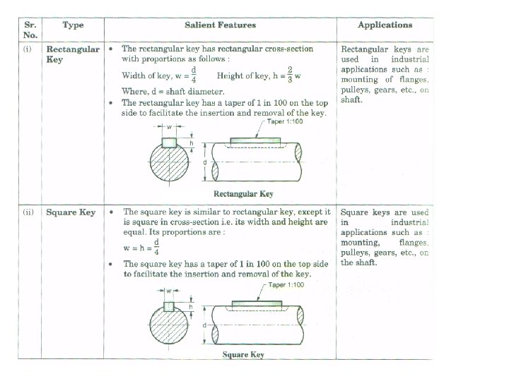
KEYS Ø A key is the piece inserted in a axial direction between a shaft and hub to prevent relative rotation but allow sliding movement along the shaft if required. Ø Keys are temporary fastening and are always made of mild steel because they are subjected to shearing and compressive stresses caused by the torque they transmit. Ø a keyway is the groove cut in the shaft or hub to accommodate a key. Key ways can be milled horizontally or vertically.

KEYS Defination: The key can be defined as a machine element which is used to connect the transmission shaft to rotating elements like pulleys, gears, sprockets or flywheels. Functions: • To prevent the relative motion between the shaft and the hub of rotating element like : gear, pulley, or sprocket. • To transmit the torque from the shaft to the rotating element or vice-versa. • The selection of the type of key for a given application depends upon the following factors: – Power to be transmitted – Tightness of fit – Stability of connection – Cost

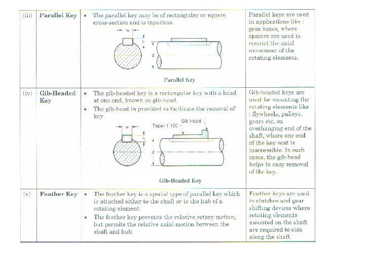
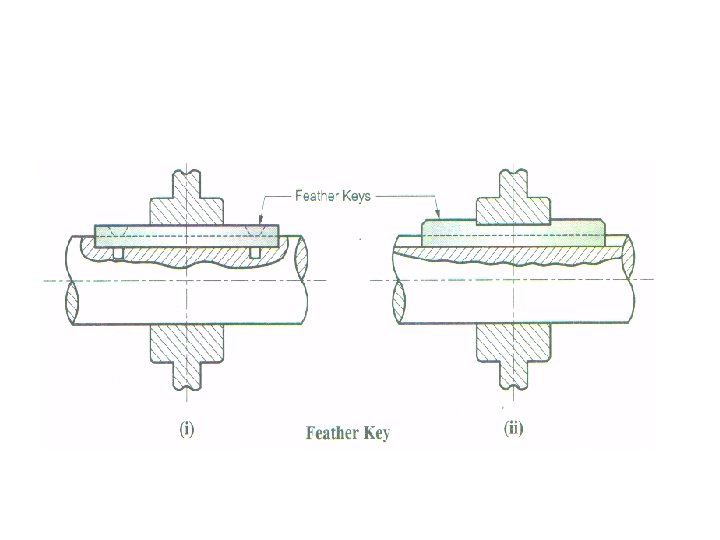
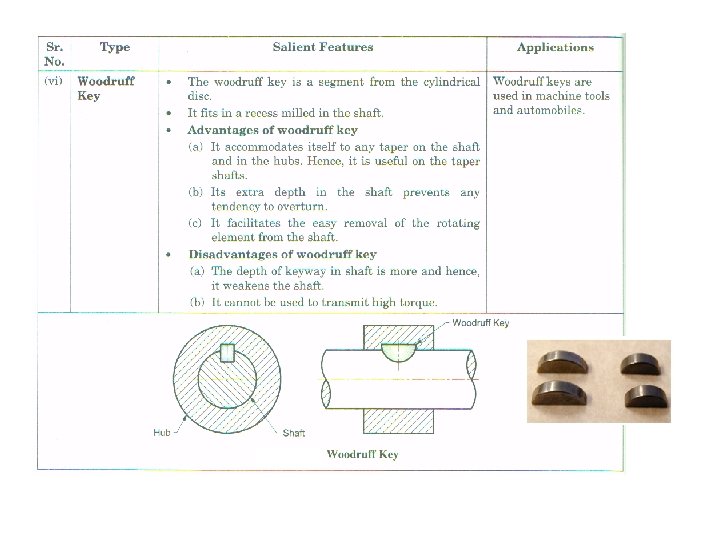
Types of keys Ø Saddle keys » Hollow saddle key » Flat saddle key Ø Sunk keys » Taper sunk keys » Parallel sunk keys » Feather keys – Woodruff key (adjustable key) Taper sunk key Ø Round keys Taper sunk key Ø Tangent keys Ø Splines Gib-headed key » Parallel pin » Taper pin Woodruff key

Kennedy keys consist of two tapered square keys placed 90 apart. Applications : Kennedy keys are used in heavy duty industrial applications. A round key is a straight pin of circular crosssection, fitted into a common hole drilled at the interface of shaft and hub Applications : Round keys and taper pins are commonly used for low power drives. A taper pin is a pin of circular cross-section, fitted into a common hole drilled through the hub and shaft, which is perpendicular to the axis of the shaft.

COUPLING Ø Coupling is the mechanical element used to connect two shafts of a transmission system and transmit the torque from one shaft to another. Shaft 1 (driving) Shaft 2 (driven) Fig. Coupling

Functions of Coupling Ø It connects the shafts of two different units such as an electric motor and machine. Ø It introduces mechanical flexibility between two connected units and tolerates small misalignment between the connecting shafts. Ø It reduces the transmission of vibrations and shocks between two connected units.

Requirements of good coupling Ø It should transmit the full power from one shaft to another. Ø It should keep the shafts in perfect alignment. Ø It should absorb the slight misalignment that may be present between the driver and drive shaft. Ø It should be easy to connect and disconnect. Ø It should have no projecting parts.

Types of Couplings • Rigid coupling Ø Muff or sleeve coupling Ø Split muff or clamp coupling Ø Flange coupling • Flexible Coupling ØBushed-pin type ØUniversal or Hooke's ØOldham’s coupling Bushed-pin type

Types of couplings • Oldham's coupling • Universal coupling

Rigid Couplings Ø Rigid couplings are used to connect two shafts which are perfectly aligned. Ø These couplings are not capable of tolerating any misalignment between two shafts. Ø These couplings are not capable of absorbing shocks and vibrations. Ø These are simple and inexpensive.

Protected type rigid flange coupling • It consists of two flanges: one keyed to the driving shaft and other to the driven shaft. One of the flange has projected portion and other has a corresponding recess. This helps to bring two shafts in line and maintain the alignment. • The two flanges are coupled together by means of bolts and nuts. The number of bolts used are generally three, four or six. The two keys are staggered at right angles along the circumference of the shafts. • The flanges are made of cast iron, cast steel, or steel. The torque is transmitted from the driving shaft to the left side flange through the key. It is then transmitted from the left side flange to the right side flange through the bolts. Finally, it is transmitted from the right side flange to the driven shaft through the key. Advantages 1. The flange coupling is easy to assemble and disassemble. 2. It has high torque transmitting capacity. Disadvantages 1. The flange coupling cannot tolerate misalignment between driving and driven shafts. 2. It requires more radial space. Applications The flange coupling is used for connecting electric motor to pump or compressor.

Protected type rigid flange coupling

Bearings Ø Bearing is a machine element which supports another moving machine element called as journal. Ø It permits a relative motion between the contact surfaces of the members. Ø Due to relative motion between the contact surfaces, there is friction and wear hence lubricant is required. Ø The commonly used lubricants are vegetable oil, silicon oil, grease, etc. Bearing

Function of a Bearing Ø The main function of a rotating shaft is to transmit power from one end of the line to the other. – It needs a good support to ensure stability and frictionless rotation. The support for the shaft is known as “bearing”. Ø The shaft has a “running fit” in a bearing. All bearing are provided some lubrication arrangement to reduced friction between shaft and bearing. Ø It also sustains the forces acting on the shaft or axle and transmits them to the frame of the machine.

Bearings are classified under two main categories: – Plain or slider bearing : • In which the rotating shaft has a sliding contact with the bearing which is held stationary. Due to large contact area friction between mating parts is high requiring greater lubrication. – Rolling or anti-friction bearing : • Due to less contact area rolling friction is much lesser than the sliding friction , hence these bearings are also known as antifriction bearing.

Rolling contact bearing- Ball bearing Major parts: • • Outer race Inner race Rolling element Separator or retainer

Types of ball bearings 1. 2. 3. 4. Single row deep-groove ball bearings Double row deep-groove ball bearings Angular contact bearings Self-aligning bearings

Roller bearing

Clutches Ø Clutch is a mechanism to transmit rotary motion from one shaft (driving shaft) to another coincident shaft, (driven shaft), as and when required, without stopping the driver shaft. Ø Clutches are also required to disengage the drive from engine to gearbox for changing the gears. Ø During slowing of vehicle or stopping, the clutch is used to disengage engine from drive wheels and enable smooth stopping of vehicle. Ø Since clutch is of friction material, it also takes care of speed and torque variation from engine crankshaft to gearbox input shaft.
, the clutch")
Functions of the clutch • When clutch is engaged (clutch pedal position-up), the clutch transmits maximum power from engine crankshaft to gearbox input shaft. • When clutch is disengaged (clutch pedal positiondown), the clutch allows driver to shift the transmission in various gear positions (first, second, third, etc. ) • When clutch is engaging (clutch pedal positionmoving up), the clutch accommodates for minor slippages and hence provides smooth drive transmission without jerks.

Types of Clutches 1. Friction clutches ØThese clutches work on the friction principle that when two independent disc have relative motion between them, friction is caused. ØFriction clutches are the most commonly used clutches. 2. Positive clutches ØThese clutches are used when positive drive is required. ØThese type of clutches are used in sprocket wheels, gears, pulleys, etc.

Single Plate Clutch ØSingle plate is the most commonly used type of clutch on automobiles. ØIt provides quicker disengagement. ØIt consists of clutch disc, pressure plate, and a cover assembly which are bolted to the engine flywheel.

Single plate clutch Major components • • Flywheel Friction plate Pressure plate Thrust spring Release lever Clutch cover Clutch shaft Thrust bearing

Advantages & Disadvantages Advantages : • • Simple design of construction and working. Better heat dissipation from single plate. Gear changing with single plate clutch is easier. It has better torsional vibration absorbing capacity. Disadvantages : • For higher power transmission, the surface area of clutch plate increases and thereby increasing the overall size of clutch. • Clutch pedal force required is higher.

Brakes Ø Brake is a device with the help of which artificial frictional resistance is applied to a moving machine member, in order to stop or retard the motion of a machine. Ø While performing this function, the brake absorbs either kinetic energy of the moving member or potential energy given by objects being lowered by cranes, elevators, etc. Ø The energy absorbed by the brake is dissipated in the form of heat in the surrounding air, so that excessive heating of the brake lining does not take place.

Types of brakes Mechanical brakes Hydraulic brakes Brakes Magnetic brakes 1. Block brakes 2. Disc brakes 3. Band brakes 4. Internal or external shoe brake Electric brakes

Disc Brake Ø Disc brakes are more efficient and now-a-days being adopted on large scale in the automotive segment. Ø It consists of a rotating brake disc mounted on the wheel and two friction pads positioned on either side of the disc. Ø The pressing of the stationary brake pads on the revolving disc causes friction, resulting in braking.
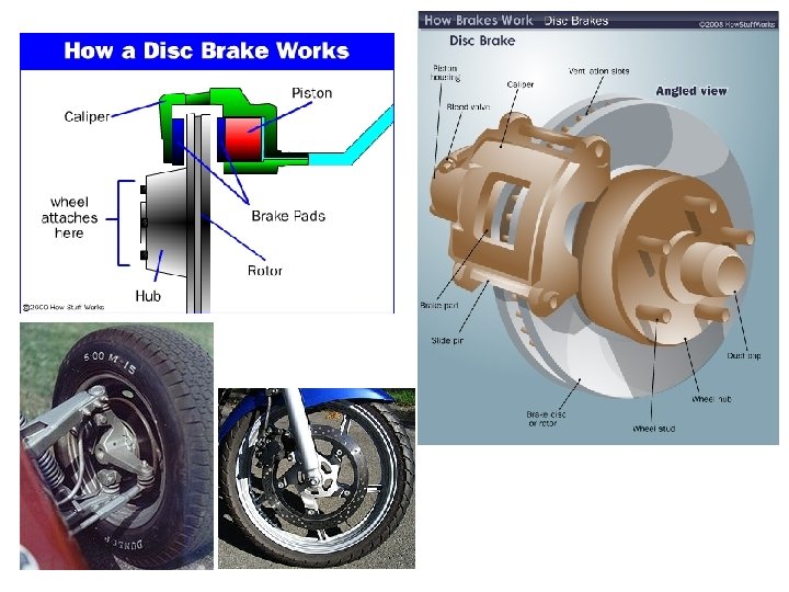

Advantages & Disadvantages Advantages : • The operation and assembly of disc brake is much simpler. • As the friction pads are flat, the wear and tear is uniform. • Heat dissipation is faster. Disadvantages : • The overall system cost is higher due to hydraulic caliper and fluid lines. • The frictional area of pads is less, thereby requiring high pressure intensity fluid.

Part B Power transmission devices Syllabus • Construction, working, comparison and applications of: Belt drive (flat and V-belt), chain drive and spur gear drive arranged with simple gear train.

Introduction Ø Usually power is transmitted by means of belts, ropes, chains and gears. Ø For large distances, belt, ropes and chains are used and for smaller distances, gears are used. Ø Belts, ropes and chains are flexible type of connectors. Ø Owing to slipping and straining action, belts and ropes are not positive drive. Ø On the other hand, chains and gears are positive drives (rigid).

Belt drives q It consists of 3 elements: • Driving or head pulley • Driven or tail pulley • Endless belt q Power is transmitted because of frictional grip. Belt drive q. Speed ratio of belt drive: • speed ratio = speed of driving pulley/speed of driven pulley = n/N = D/d = (D+t)/(d+t) Where, n and N = speed of driving and driven pulley in RPM d and D = diameters of driving and driven pulleys in mm t = thickness of belt in mm.

Types of belts Materials used for belts • Leather • Cotton • Rubber Sr. No. Type Characteristics 1. Flat belt § § Rectangular C/S Moderate amount of power Used when pulleys are not more than 8 m apart Crowned pulleys are used 2. V-Belt § Trapezoidal C/S § Large amount of power and pulleys are nearer § Pulleys are provided with groove 3. Circular belt § § Circular C/S Large amount of power Pulleys are more than 8 m apart Pulleys are provided with groove

Comparison between flat and V-belt Sr. No. Parameter Flat belt V-belt 1. Cost Low Higher 2. Maintenance Low Higher 3. Multiple speed ratio Can be used Cannot be used 4. Simplicity of design Simple to design Complex 5. Efficiency Higher Lower 6. Long center distance Can be used Short distances 7. Power trans. Capacity Lower High 8. High speed reduction Upto 4: 1 Upto 7: 1 9. Overall size of drive Bigger size Compact size 10. Use of multiple belts Restricted for single belt Multiple belts can be used 11. Smoothness of drive More noisy at higher speeds Relatively smooth

Types of flat belt drives Open belt with idler pulley drive Open belt drive Crossed belt drive Compound belt drive

Advantages and disadvantages of belt drive • Advantages ØCan be used for long Centre distances ØAbsorb shocks and vibrations ØLubrication is not required ØNot affected due to dirt and dust ØDo not require precise alignment of shaft and pulley • Disadvantages ØLow power transmitting capacity ØCan not be used at extremely high speeds ØShorter life and more space as compared to gear drive ØNot positive drive

Chain drive Ø To avoid slipping, chain drives are used Ø Chain drive consists of chain and sprocket Ø Chains are made up of no of rigid links hinged together Ø Sprockets have projecting teeth of special profile and fit into the corresponding recesses in the chain links. Ø This drive is commonly used to transmit motion from shafts having shorter centre distances. Ø Used in bicycles, motor cycles, conveyors, road rollers, rolling mill, agricultural machinery, etc.
 chains • Good flexibility in all direction")
Types of chain drive 1. Hoisting (crane) chains • Good flexibility in all direction • Operate at maximum velocity • Links may be of oval or square shape • Oval shape is commonly used 2. Conveyor or hauling (tractive)chains • • Used for conveying materials Operate at moderate speed Chains are made of CI Links may be of hook joint or closed joint type

Advantages and disadvantages of chain drive over belt drive • Advantages ØNo slip hence perfect speed ratio ØLess space in width than belt drive ØOffers/provides less loads on the shafts ØCan be operated under low/high temperatures ØMore power transmitting capacity • Disadvantages ØMore cost ØNeeds accurate mounting and careful maintenance ØNoisy operation

Comparison between chain and belt drive Sr. No. Parameter Chain drive Belt drive 1. Drive elements Chain and sprockets Belt and pulleys 2. Type of drive Positive Non-positive 3. Power transmitting capacity High Low 4. Space requirement Less More 5. Operating conditions Can operate in adverse conditions Can not be operated in adverse conditions 6. Lubrication Required Not required 7. Operating noise More Less 8. Precise alignment Required Not required 9. Manufacturing cost More less

Gear drive Ø Gears are defined as toothed wheels which can transmit power and motion from one shaft to another shaft by means of successive engagement of teeth. Ø It is a positive drive and used for smaller centre distances. Spur gear drive Ø Smaller gear is called as pinion and larger gear is called as gear. Ø Speed ratio = speed of pinion/speed of gear = np /ng = dg /dp = Zg /Zp Where , np , ng = pinion and gear speed in RPM dg and dp = diameters of gear and pinion Zg and Zp = no of teeth on gear and pinion

Spur gear drive Ø Spur gears are used to transmit motion between two parallel shafts. Ø Simplest of all gears and easiest in production Ø Teeth of spur gear are cut along the periphery and parallel to the axis of gear. Ø They are made of steel, brass, other metals and plastics. • Advantages Ø Spur gears are easy to manufacture Ø They are made in variety of sizes from less than 25 mm to several cm in diameter. Ø Less expensive • Applications : commonly used in Ø High efficiency (upto 98 %) machine tool gear box, watches, etc. • Disadvantages Ø Not used for high speed applications Ø Noisy operation.

Gear train • A gear train is a combination of two or more gears which is used for power transmission. • It is used to obtain large speed reduction within a small space. • The nature of gear train used depends upon the required velocity ratio and the relative positions of the axes of the shafts. • They are commonly used in various machines, automobiles, clocks, ships, watches, etc. • Different types of gear trains are simple gear train, compound gear train, reverted gear train and epicyclic gear train.

Simple gear train Ø If only one gear is mounted on each shaft then it is called as simple gear train. Ø If the distance between the two gears is large, then the intermediate gears are used. Ø If number of intermediate gears are odd then the motion of driver and driven gear is same. Ø Similarly, if the number of intermediate gears are even the motion of driver and driven gear is opposite.

Comparison between gear drive and belt drive Sr. No. Parameter Gear drive Gear and pinion Belt drive 1. Drive elements Belt and pulleys 2. Power transmitting capacity High Low 3. Space requirement Less More 4. Lubrication Required Not required 5. Operating noise Moderate Less 6. Precise alignment Required Not required 7. Manufacturing cost More Less 8. Type of drive Positive Non-positive
- Slides: 59