
Dr Apiwat Muttamara Introduction Modern Manufacturing FMS CIM
- Slides: 104
Dr. Apiwat Muttamara
Introduction Modern Manufacturing FMS, CIM Workholder (Jig & fixture)
• What ’s different between Jig and Fixture • Basic Principle of workholder • Identify the types of locators and support used fro jigs and fixtures
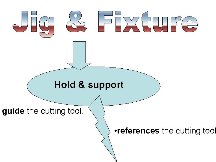
Hold & support guide the cutting tool. • references the cutting tool
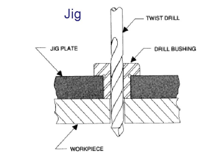
Jig
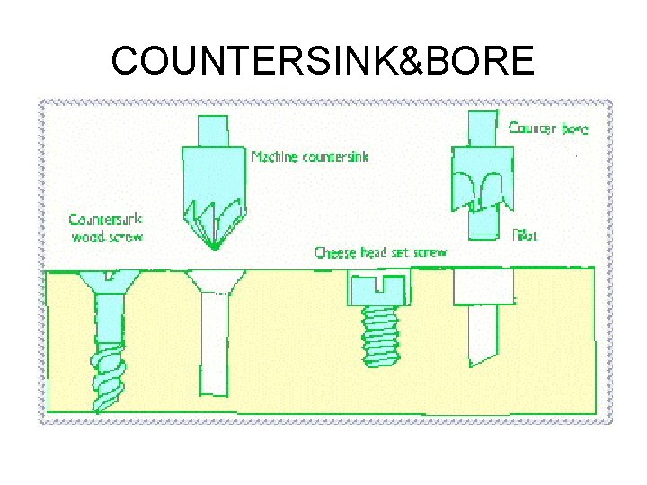
COUNTERSINK&BORE
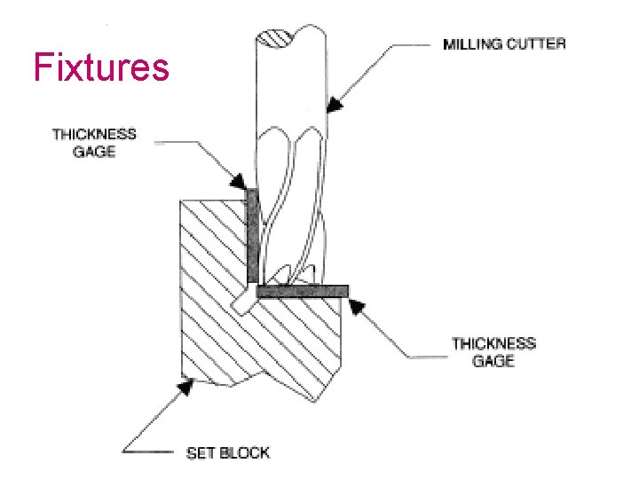
Fixtures
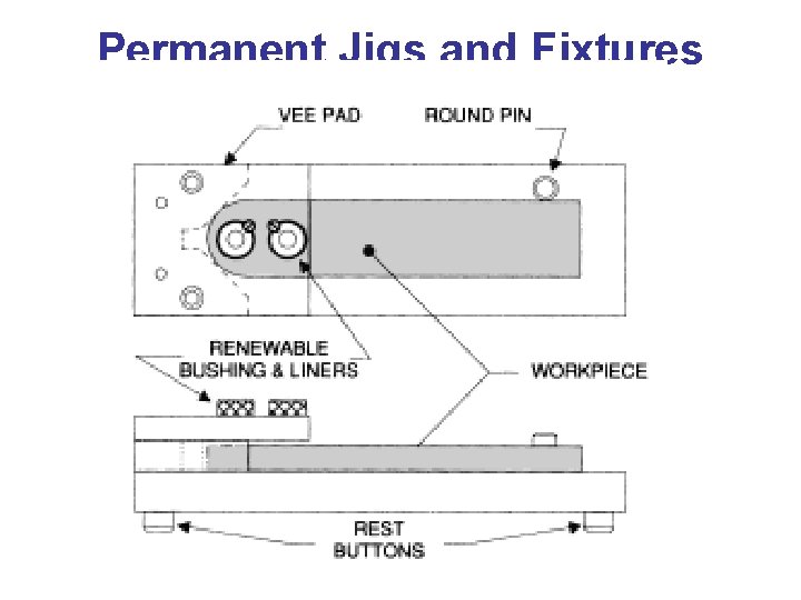
Permanent Jigs and Fixtures
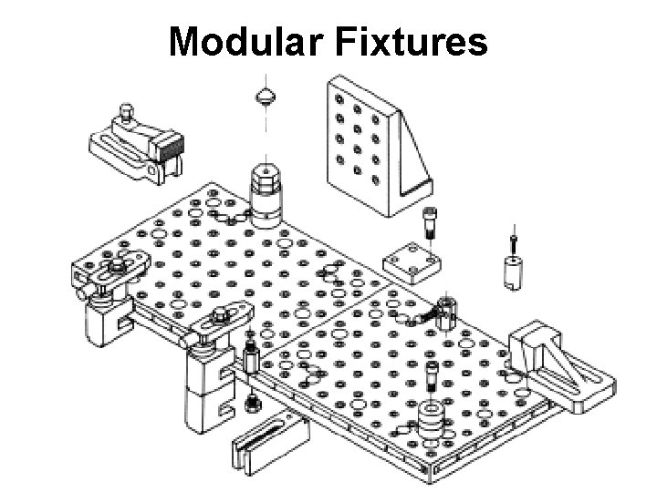
Modular Fixtures
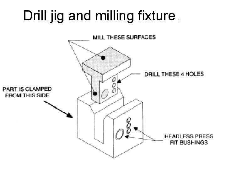
Drill jig and milling fixture.
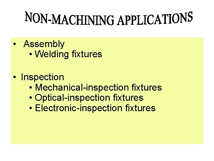
• Assembly • Welding fixtures • Inspection • Mechanical-inspection fixtures • Optical-inspection fixtures • Electronic-inspection fixtures
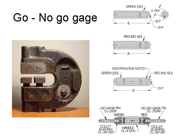
Go - No go gage
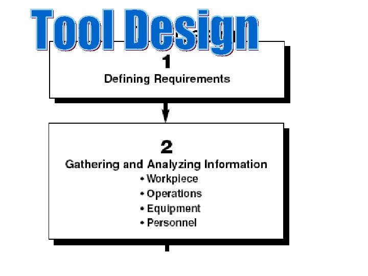
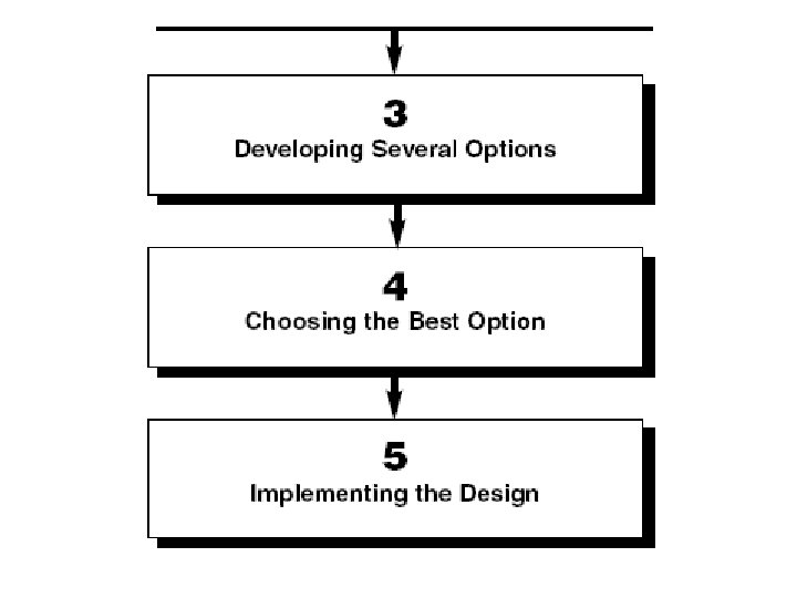
Tool Design
• Purpose and function of work holders • Consistently position workpiece relative to the tool • Hold workpiece in position against tool forces • Restrict deflection of the workpiece due to tool and holding forces
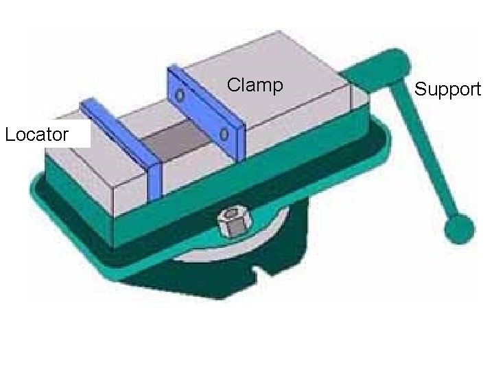
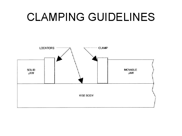
• A locator is usually a fixed part of a fixture, the purpose of which is to restrict movement of the workpiece. • A clamp is a moveable part of a fixture, the purpose of which is to provide a holding force. • A support is a fixed or moveable part of a fixture, the purpose of which is to prevent workpiece deflection under the action of imposed cutting forces or clamping forces.
Clamp Locator Support
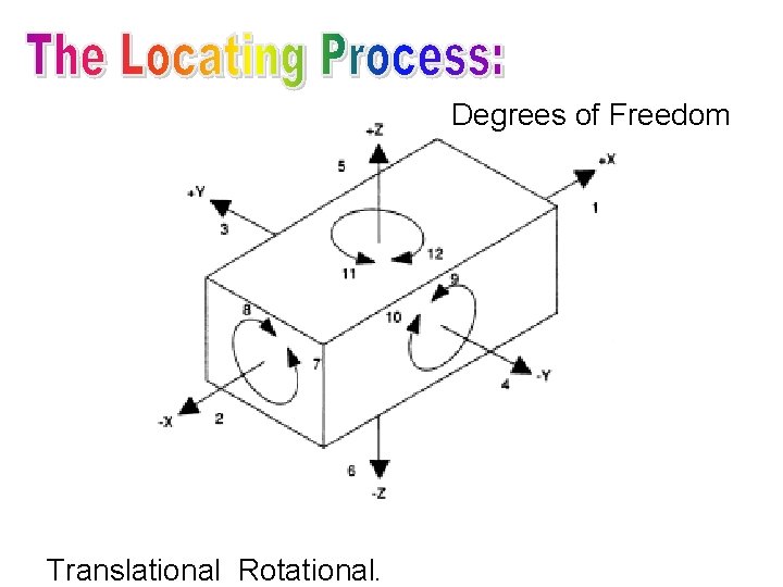
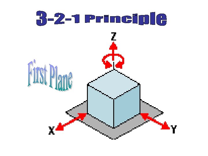
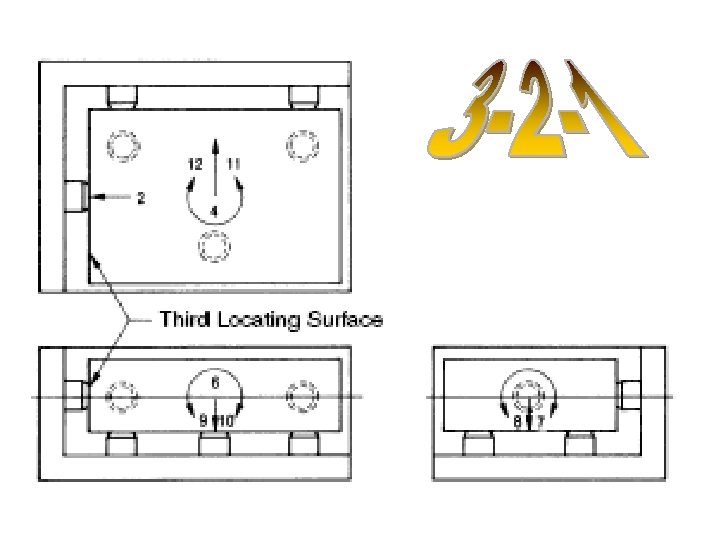
Degrees of Freedom Translational Rotational.
Two objectives when mounting a part in a fixture for machining: • . 1 Accurately position the part at the desired coordinates. • . 2 Restrict all six degrees of freedom so that the part cannot move.
First Plane
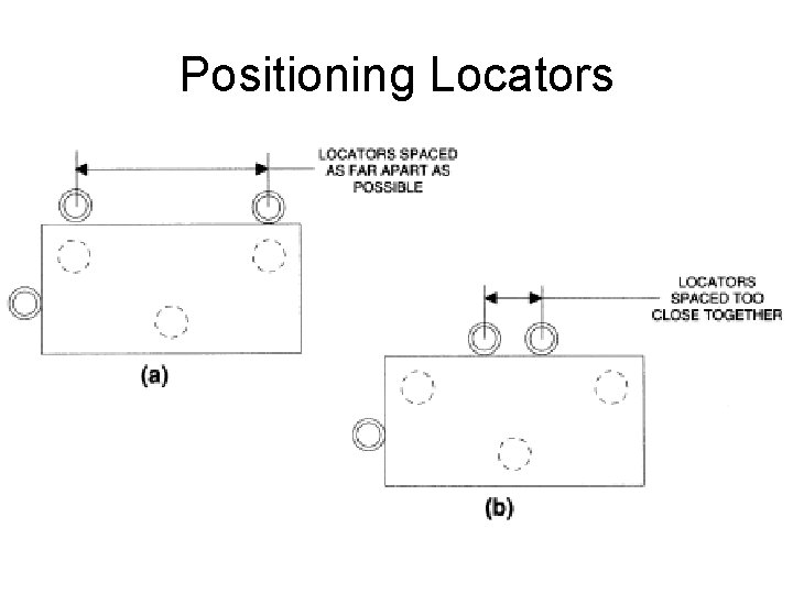
TIPS • Use the largest surface of the part for the first ("primary") reference plane. • Position the three support points as far apart as possible. • If more than three support points are required to prevent deflection, make the additional points adjustable.
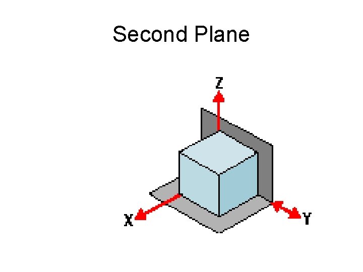
Second Plane
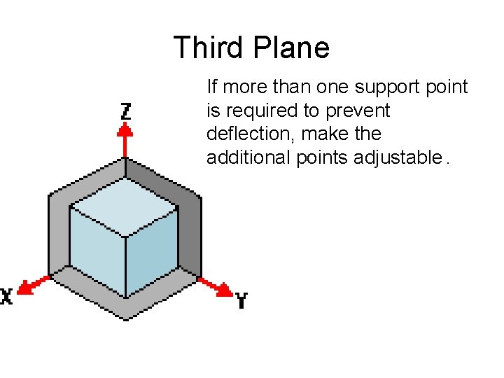
Third Plane If more than one support point is required to prevent deflection, make the additional points adjustable.
9 degrees fix
Positioning Locators
BASIC PRINCIPLES OF LOCATING • To perform properly, workholders must accurately and consistently position the workpiece relative to the cutting tool, part after part. To accomplish this, the locators must ensure that the workpiece is properly referenced and the process is repeatable.
• Workpiece should automatically come to rest against locators despite operators skill or effort. • Location system must consistently position all workpieces in relations to the tool despite the variations in the working environment. • e. g. surface irregularities, wear of locators, dirt, temperatures difference.
• . 1 Establishing a locating plane • Surface should be machined to insure accurate location • Choose locating point as far as possible.
• . 2 Part size • Number of locator used to reference a part normally depends on the part size. • 3 -2 -1 principle determines the minimum number required • When holding force cannot be applied more than six locators can be used • Less operator skill is required when placing the workpiece in the holder • To Increase center line control
. 3 Stability • • • Workpiece is unstable when placed on the locators, the workpiece tends to lift or rock away from one or more locators. Place locators far for more stability and to minimize the effect of wear of locators and workpiece irregularity. Top heavy workpiece may led to stability Poorly placed holding force Not enough locators
. 4 Cutting pressures • Try to place locator opposite of the tool force to avoid deflection of the workpiece. • Where possible, tool-forces should be such that they force the workpiece into contact with the locators. • Holding forces should not be in the opposite direction to the tool forces
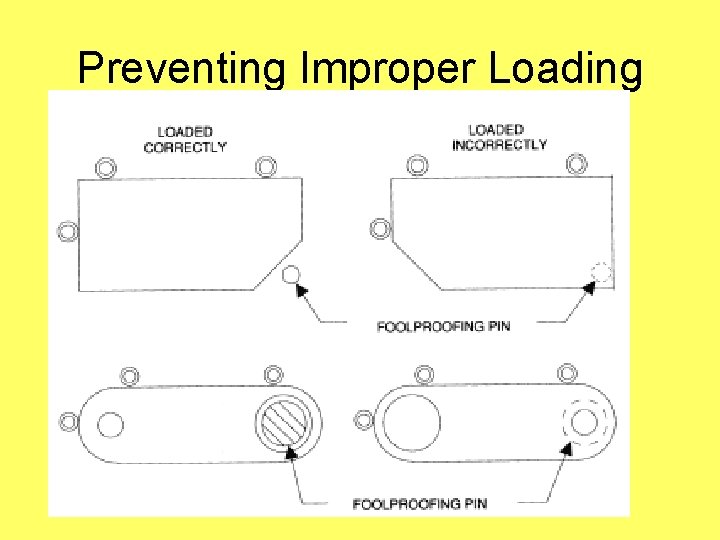
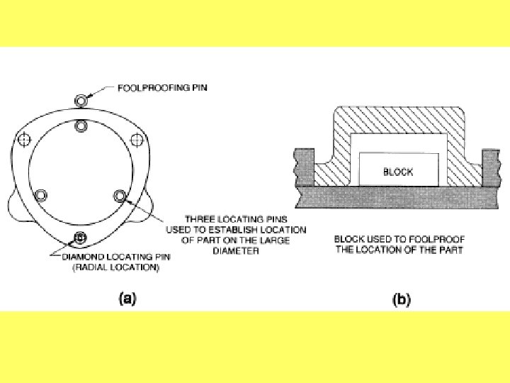
. 6 Fool-proofing • Process of position locators such that part will only fit in the proper position. Achieved by foolproofing pin.
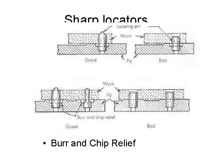
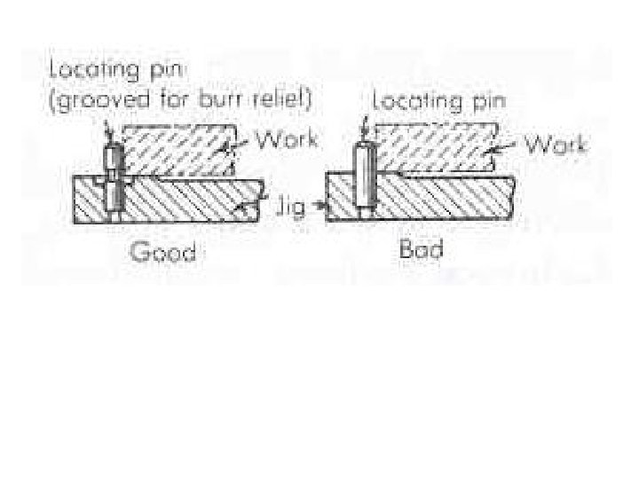
Chip removal • Chips and burr on locating surface can cause wear and disturb proper location. • . 1 Make locators easy to clean 2. Make them self cleaning 3. Protect them
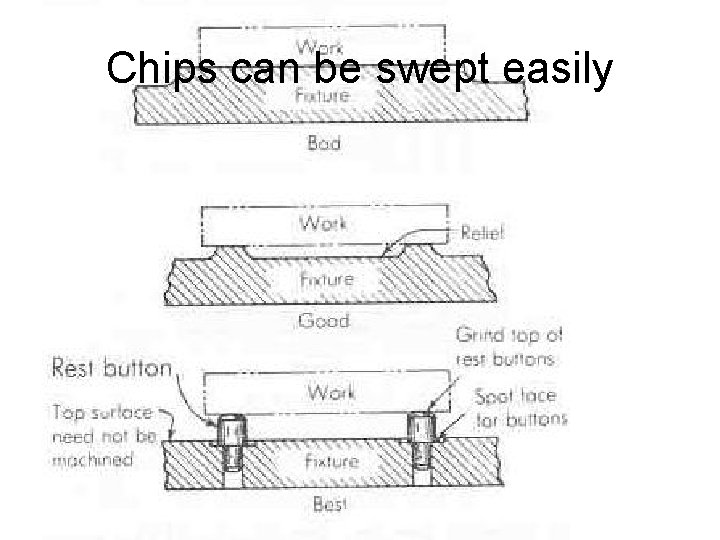
Chips can be swept easily
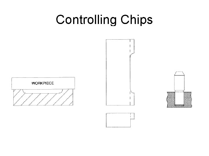
Controlling Chips
Sharp locators • Burr and Chip Relief
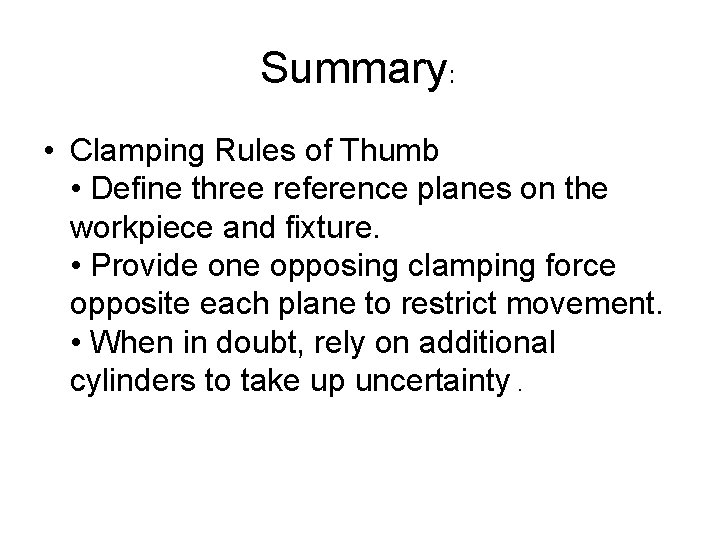
Summary: • Clamping Rules of Thumb • Define three reference planes on the workpiece and fixture. • Provide one opposing clamping force opposite each plane to restrict movement. • When in doubt, rely on additional cylinders to take up uncertainty.
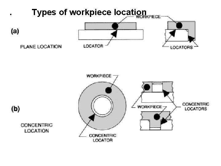
. Types of workpiece location
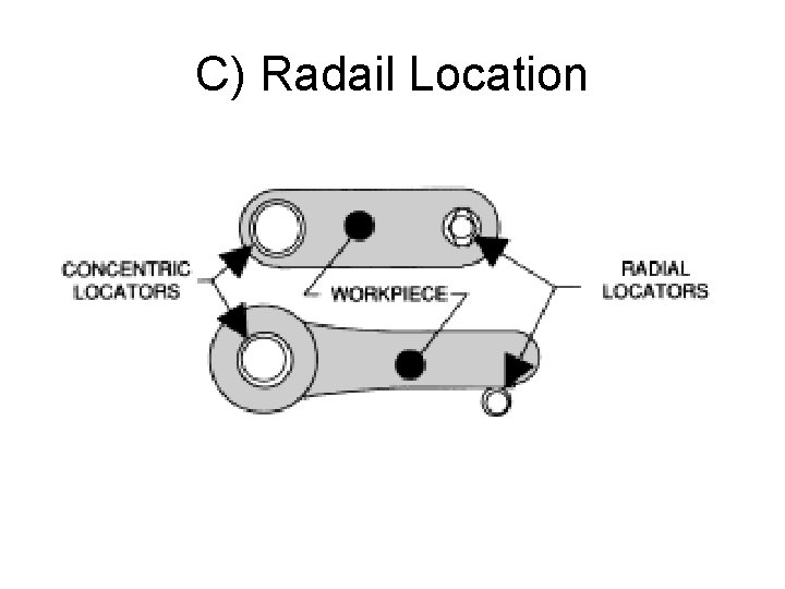
C) Radail Location
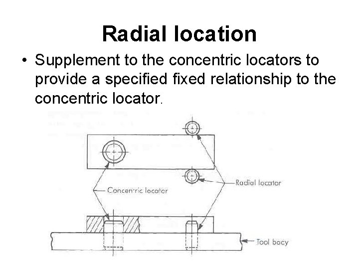
Radial location • Supplement to the concentric locators to provide a specified fixed relationship to the concentric locator.
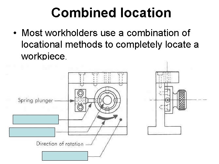
Combined location • Most workholders use a combination of locational methods to completely locate a workpiece.
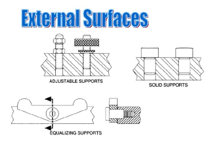
• . 1 External locators • Devices used to locate the part from external surface. • Two basic forms of external locators are fixed or adjustable. •
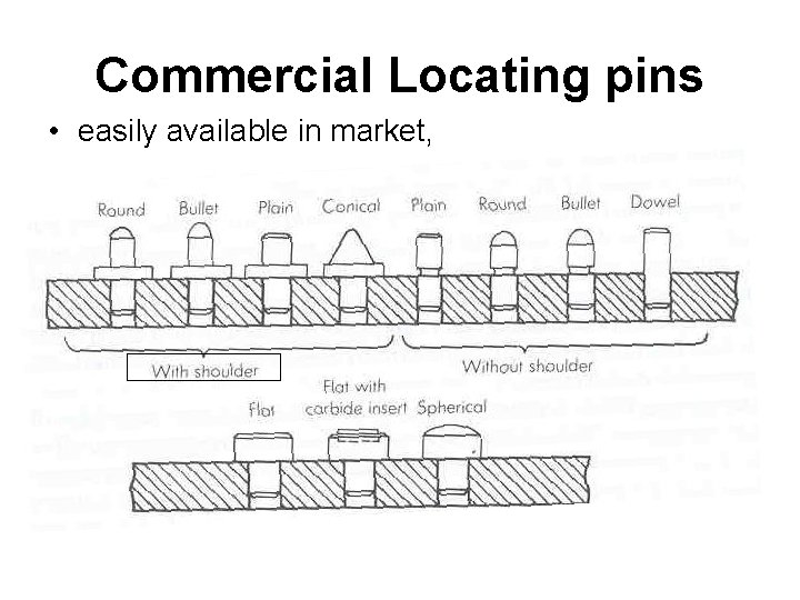
Commercial Locating pins • easily available in market,
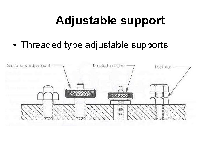
Adjustable support • Threaded type adjustable supports
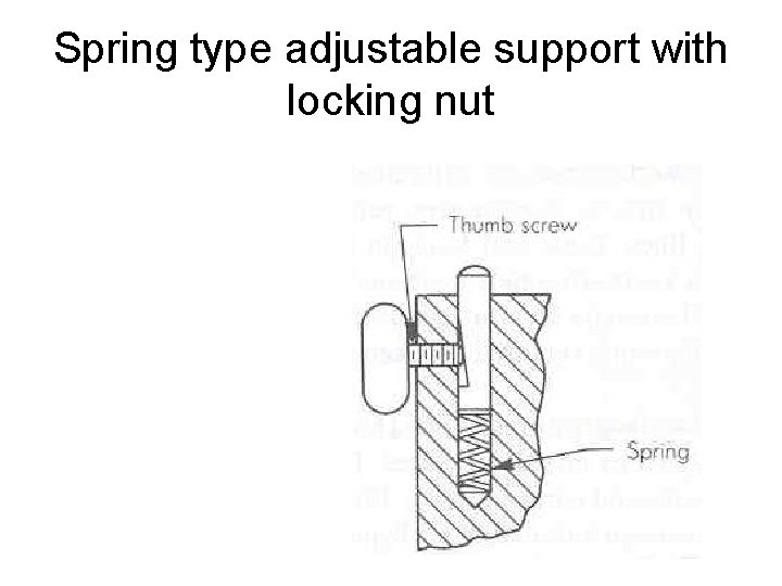
Spring type adjustable support with locking nut
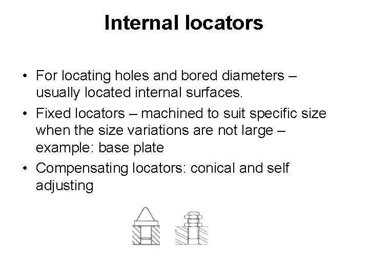
Internal locators • For locating holes and bored diameters – usually located internal surfaces. • Fixed locators – machined to suit specific size when the size variations are not large – example: base plate • Compensating locators: conical and self adjusting
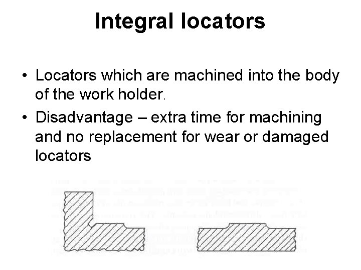
Integral locators • Locators which are machined into the body of the work holder. • Disadvantage – extra time for machining and no replacement for wear or damaged locators
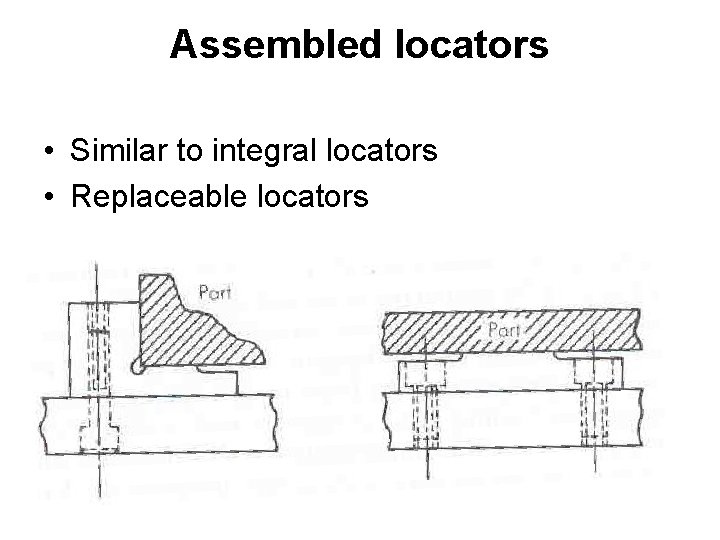
Assembled locators • Similar to integral locators • Replaceable locators
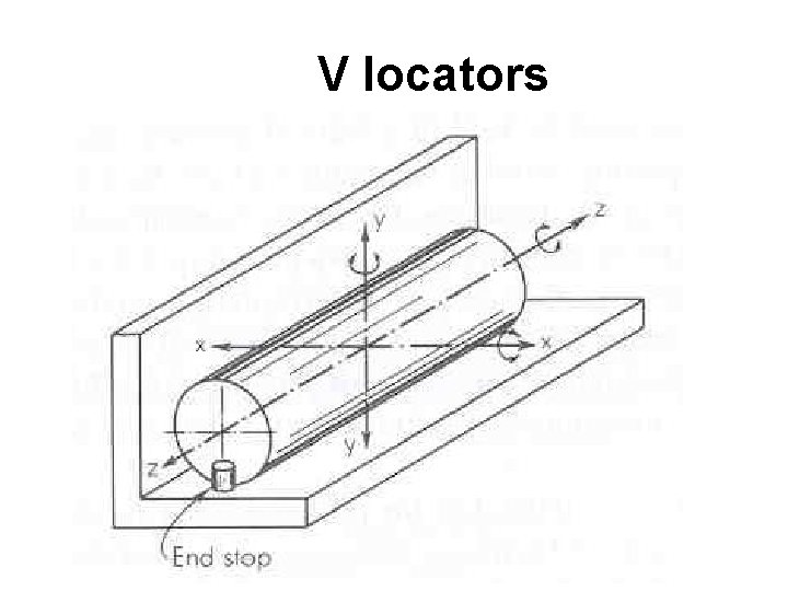
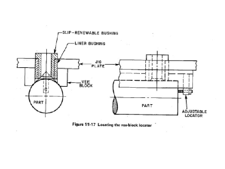
V locators
• Cylinder can come along upward Y (1), forward X(1) , Backward Z(1) and rotation along Z ( 2) – 5 movement is possible.
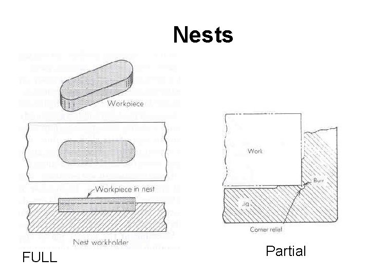
Nests FULL Partial
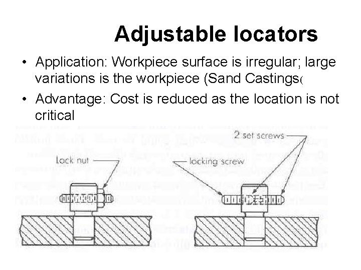
Adjustable locators • Application: Workpiece surface is irregular; large variations is the workpiece (Sand Castings( • Advantage: Cost is reduced as the location is not critical
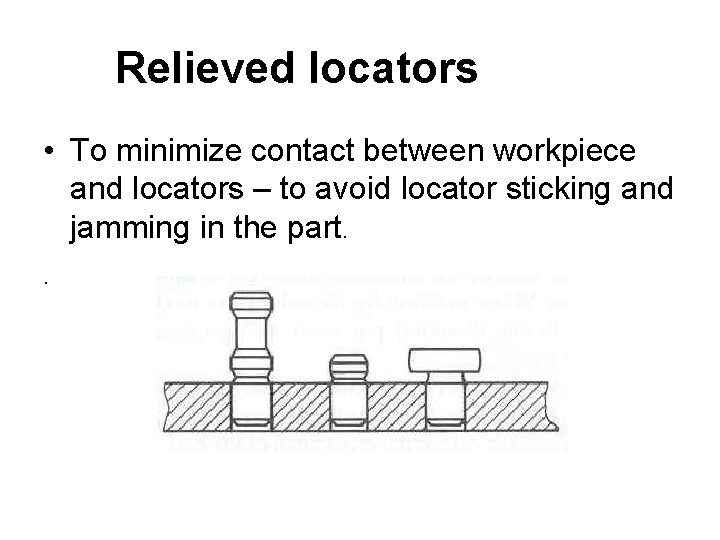
Relieved locators • To minimize contact between workpiece and locators – to avoid locator sticking and jamming in the part. .
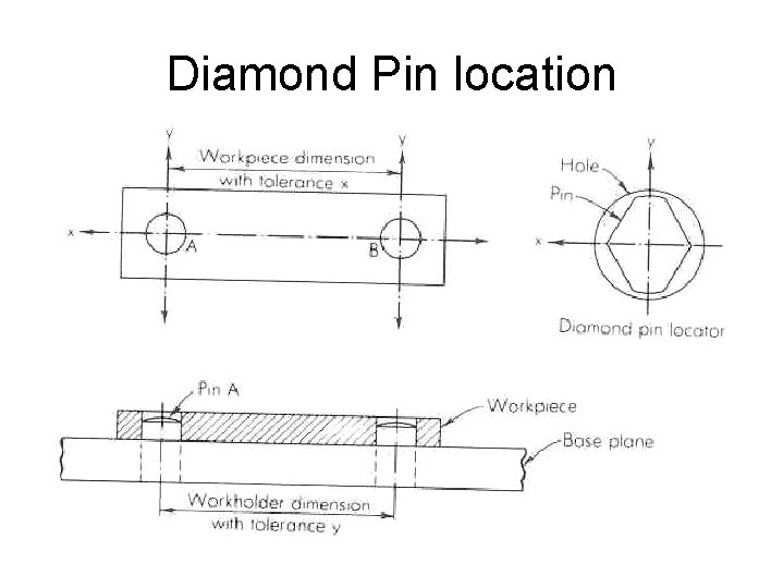
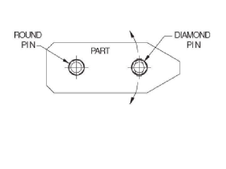
Diamond Pin location
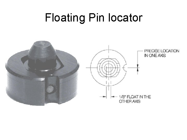
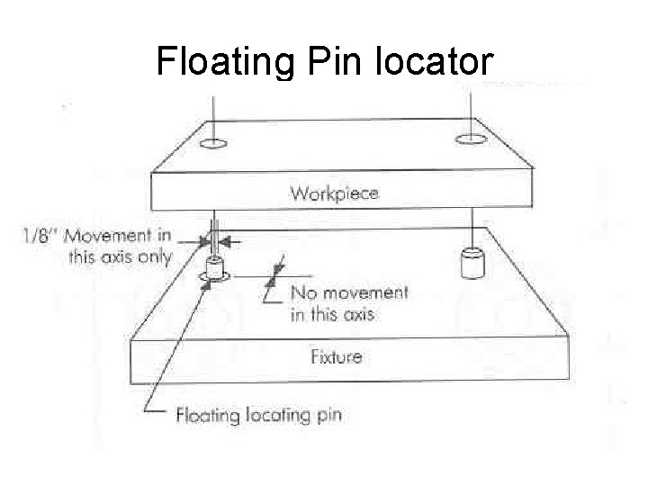
Floating Pin locator
Floating Pin locator
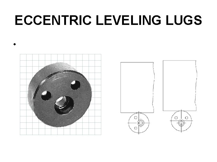
ECCENTRIC LEVELING LUGS •
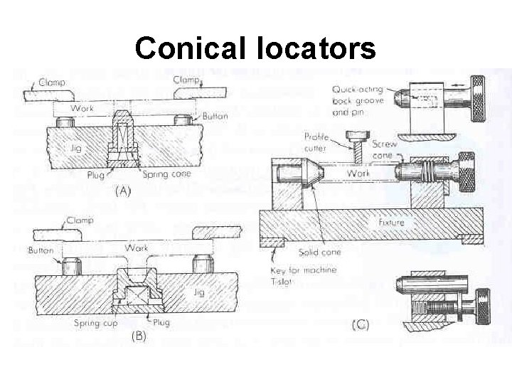
Conical locators
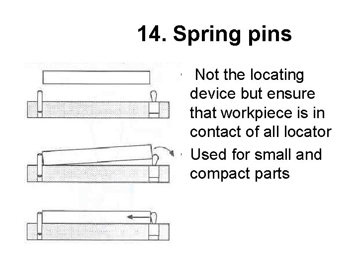
14. Spring pins • Not the locating device but ensure that workpiece is in contact of all locator • Used for small and compact parts
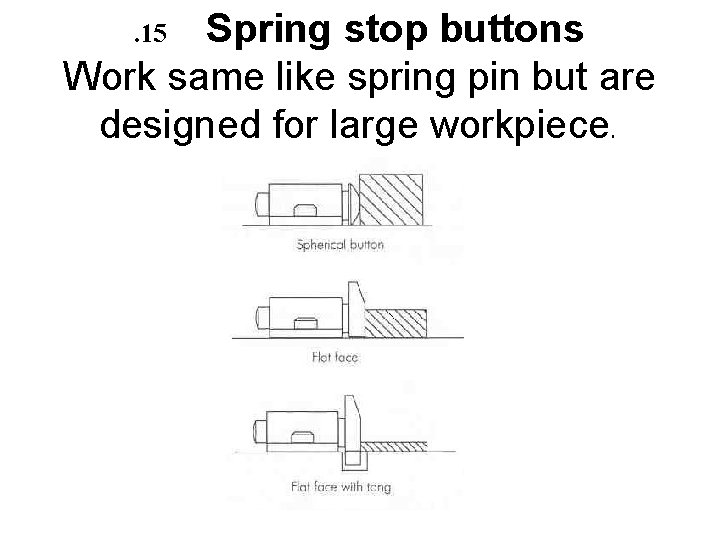
. 15 Spring stop buttons Work same like spring pin but are designed for large workpiece.
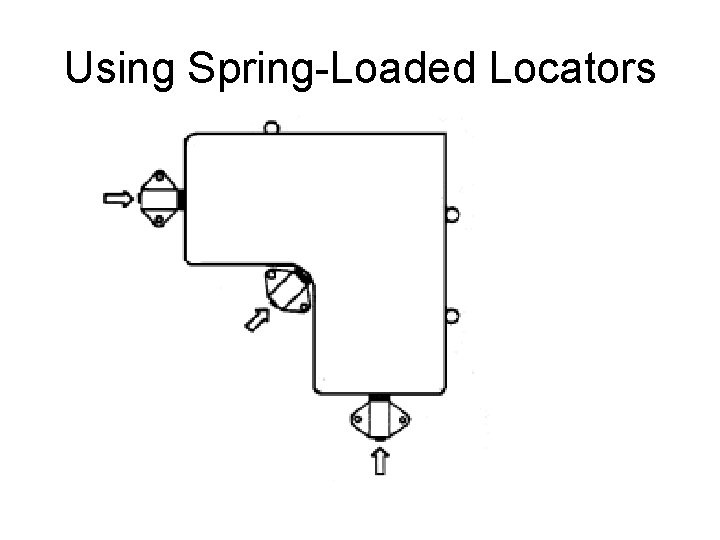
Using Spring-Loaded Locators
Today’s Agenda • • Type of Locator Trick of Design Clamping Principle Jig Design
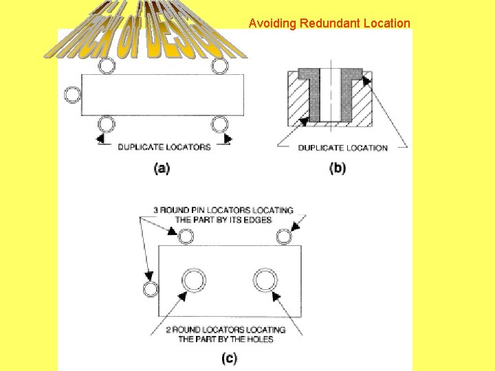
Avoiding Redundant Location
Preventing Improper Loading
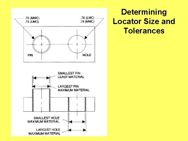
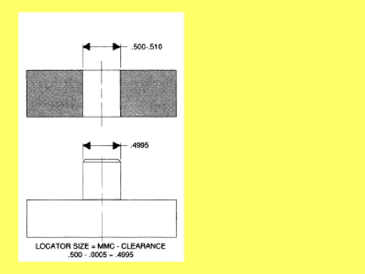
Determining Locator Size and Tolerances
CLAMPING GUIDELINES
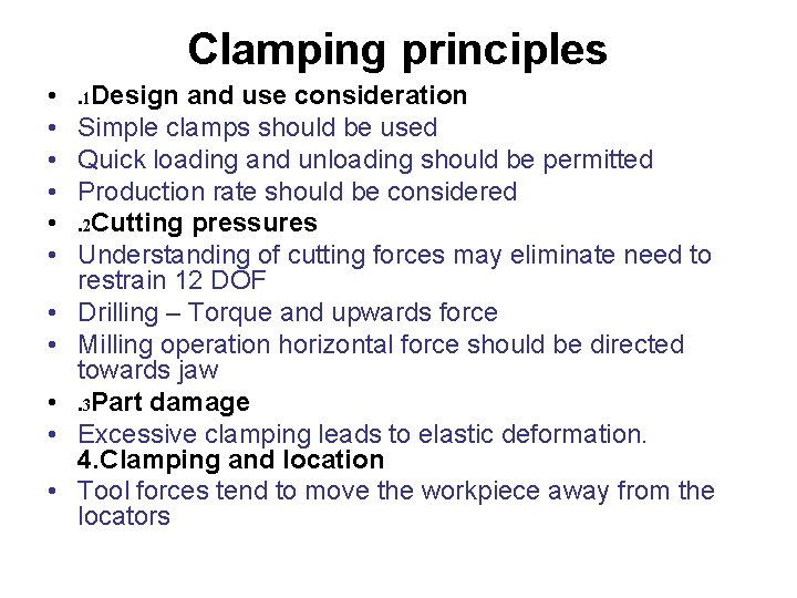
Clamping principles • • • . 1 Design and use consideration Simple clamps should be used Quick loading and unloading should be permitted Production rate should be considered. 2 Cutting pressures Understanding of cutting forces may eliminate need to restrain 12 DOF Drilling – Torque and upwards force Milling operation horizontal force should be directed towards jaw. 3 Part damage Excessive clamping leads to elastic deformation. 4. Clamping and location Tool forces tend to move the workpiece away from the locators
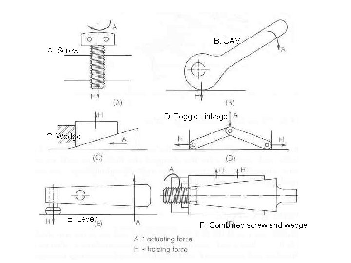
B. CAM A. Screw D. Toggle Linkage C. Wedge E. Lever F. Combined screw and wedge
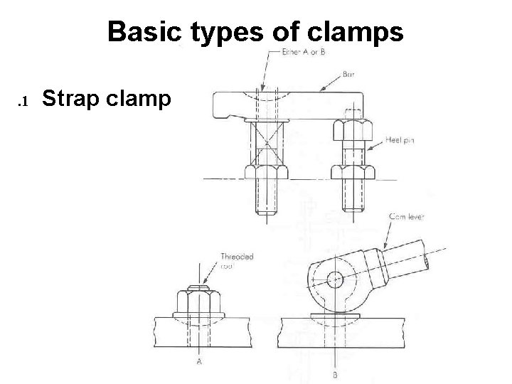
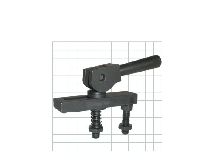
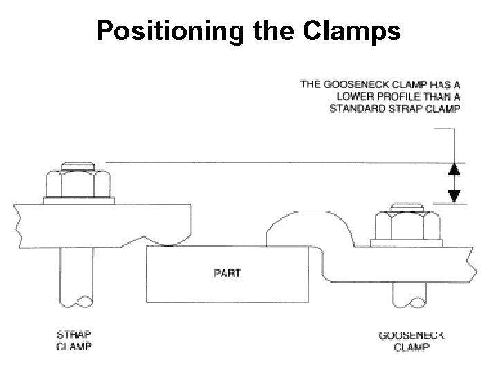
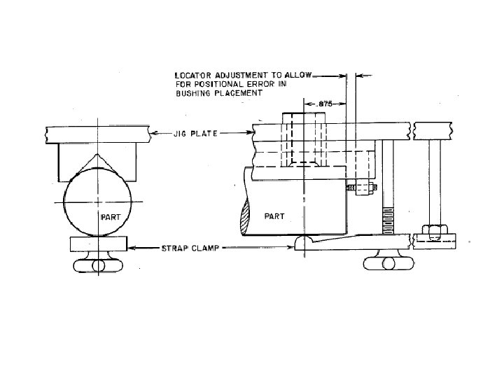
Basic types of clamps. 1 Strap clamp
Positioning the Clamps
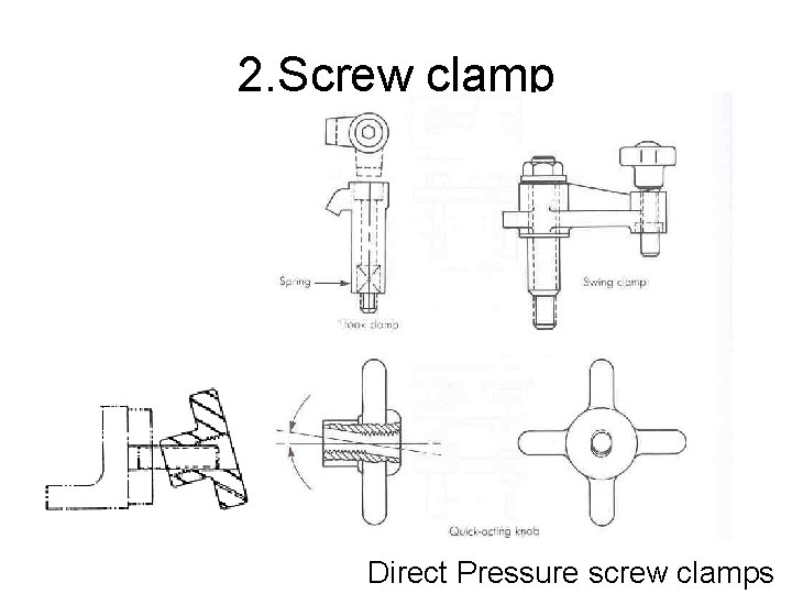
2. Screw clamp Direct Pressure screw clamps
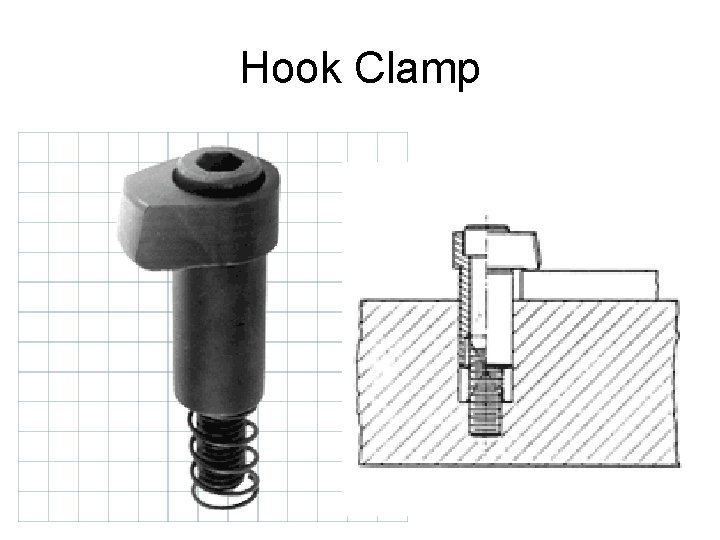
Hook Clamp
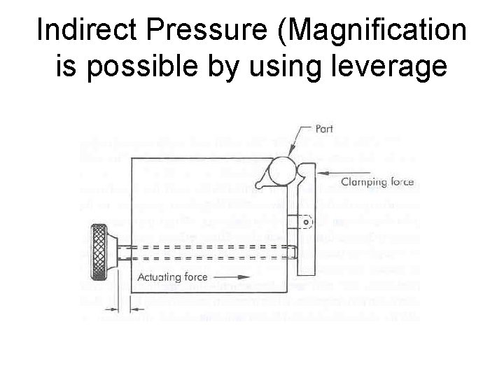
Indirect Pressure (Magnification is possible by using leverage
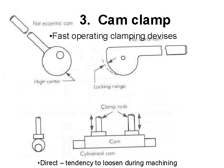
3. Cam clamp • Fast operating clamping devises • Direct – tendency to loosen during machining
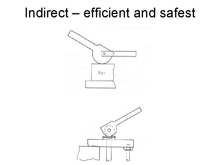
Indirect – efficient and safest
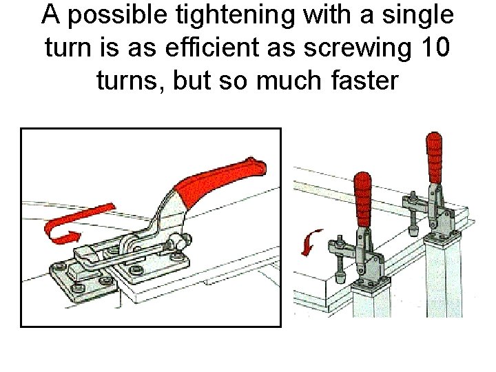
4. Toggle clamp • Fast clamping and release actions • Move completely clear of the workpiece • High ratio of holding force to actuation force • Limited range of movement • Inability to compensate for different thickness (suitable to only slight changes of workpiece thickness(
A possible tightening with a single turn is as efficient as screwing 10 turns, but so much faster
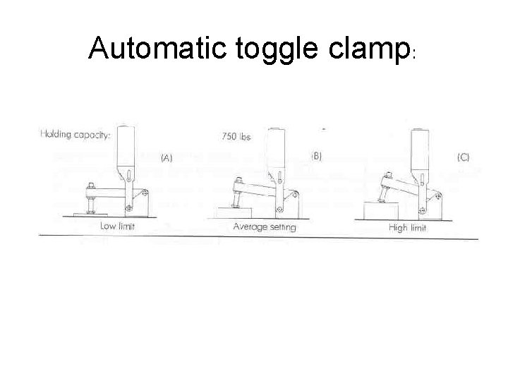
Automatic toggle clamp:
• • • • A. Definition Jigs are work holders, which are designed to hold, locate, and support a workpiece while guiding the cutting tool throughout its cutting cycle. Drill jigs are – drilling, tapping, reaming, countersinking, counter boring, chamfering, and spot facing. B. Design considerations. 1 General, machine and process General Consideration Justification of manufacturing cost reduction Machine Consideration. 1 Size, Type, and Capabilities of machine. 2 Machine should be capable of handling the part – shape, size and accuracy. 3 Enough space to mount Workholding device. 4 Tool designer must know about – table size, “T” slot size, machine travel axis
Jig Design • Process Consideration • . 1 Consider all manufacturing steps • . 2 If the part is not pre-processed first-operating jigs are used to make hole to serve for location purpose is subsequent steps. • . 3 Multiple jigs and fixtures can be used for one part • . 4 Chip removal should be considered for each manufacturing step •
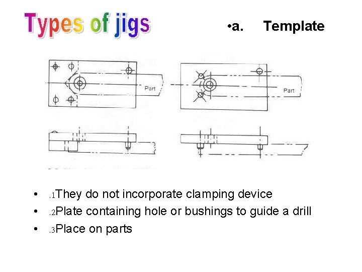
• a. Template • . 1 They do not incorporate clamping device • . 2 Plate containing hole or bushings to guide a drill • . 3 Place on parts
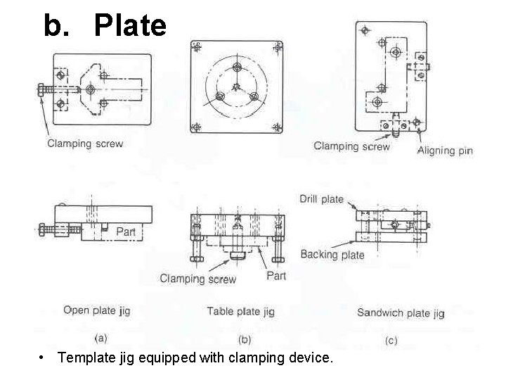
b. Plate • Template jig equipped with clamping device.
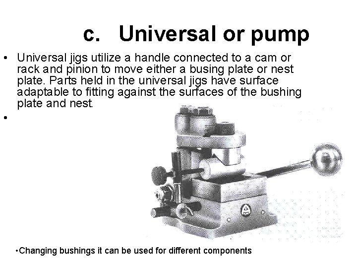
c. Universal or pump • Universal jigs utilize a handle connected to a cam or rack and pinion to move either a busing plate or nest plate. Parts held in the universal jigs have surface adaptable to fitting against the surfaces of the bushing plate and nest. • • Changing bushings it can be used for different components
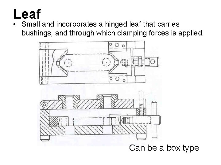
Leaf • Small and incorporates a hinged leaf that carries bushings, and through which clamping forces is applied. Can be a box type
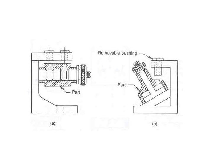
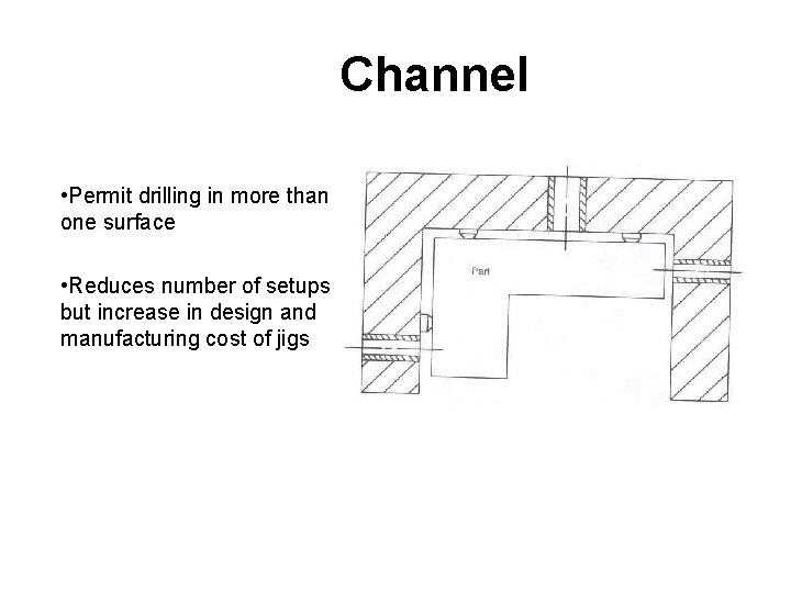
Channel • Permit drilling in more than one surface • Reduces number of setups but increase in design and manufacturing cost of jigs
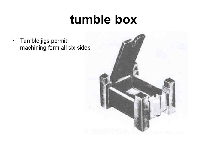
tumble box • Tumble jigs permit machining form all six sides.
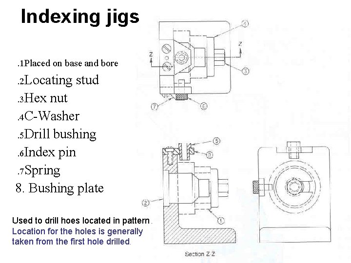
Indexing jigs. 1 Placed on base and bore. 2 Locating stud. 3 Hex nut. 4 C-Washer. 5 Drill bushing. 6 Index pin. 7 Spring 8. Bushing plate Used to drill hoes located in pattern. Location for the holes is generally taken from the first hole drilled.
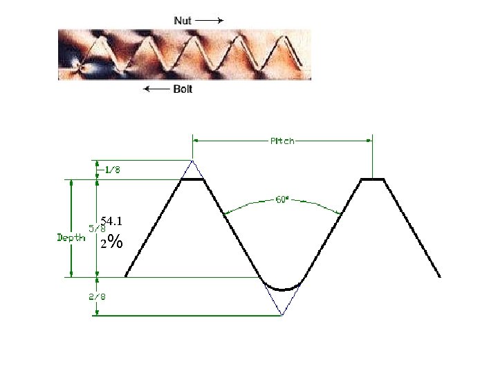
54. 1 2%
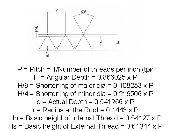
P = Pitch = 1/Number of threads per inch (tpi( H = Angular Depth = 0. 866025 x P H/8 = Shortening of major dia = 0. 108253 x P H/4 = Shortening of minor dia = 0. 216506 x P d = Actual Depth = 0. 541266 x P r = Radius at the Root = 0. 1443 x P Hn = Basic height of Internal Thread = 0. 54127 x P Hs = Basic height of External Thread = 0. 61344 x P