DPT 213 MANUFACTURING PROCESS II Chapter 6 Electrical
 Wire Cut")
 Wire Cut n n n Introduction To EDM Cutting With")


 Wire Cut")


 and the XY wire guide")


- Slides: 35
DPT 213 MANUFACTURING PROCESS II Chapter 6 : Electrical Discharge Machine (EDM) Wire Cut
Electrical Discharge Machine (EDM) Wire Cut n n n Introduction To EDM Cutting With EDM Working Principles of EDM. Types Of Wire EDM Machines Machine Setup
Introduction n n EDM - Electrical Discharge Machining. The machine makes use of the effects of electrical discharges, first observed in the year 1770.
INTRODUCTION TO EDM v v v v EDM was once considered a nontraditional machining method. complex and intricate shapes that are very difficult and time consuming to machine. The wire EDM uses wire and electricity to cut and wire diameter usually between 0. 002 and 0. 013 inches. Made from brass, brass alloy, and molybdenum. Smaller wire diameters can be used to cut smaller radius and very intricate shapes. Tungsten or molybdenum wires are used because their high tensile strength and high melting point.
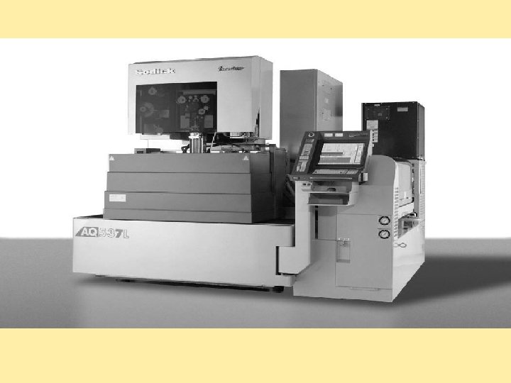
MAJOR COMPONENTS A Wire EDM system is comprised of four major components. n n (1) Computerized Numerical Control (CNC) Think of this as “The Brains. ” (2) Power Supply Provides energy to the spark. Think of this as “The Muscle. ” (3) Mechanical Section Worktable, workstand, taper unit, and wire drive mechanism. (This is the actual machine tool. ) Think of this as “The Body. ” (4) Dielectric System The water reservoir where filtration, condition of the water (resistivity/conductivity) and temperature of the water is provided and maintained
Structure of (EDM) Wire Cut
Working Principles of EDM üSimplified, the system is a two electrode system separated by a dielectric medium (nonconducting substance). üThe wire is one electrode and the workpiece being machined is the other electrode. üIt utilizes a voltage across these two electrodes which is greater than the breakdown voltage across the gap between the workpiece and the wire. üThis breakdown voltage is a function of the distance between the wire and workpiece, the insulating properties of the dielectric (fluid separating the electrodes), and the degree of pollution of the gap. üThe wire does not touch the workpiece, so there is no physical pressure imparted on the workpiece compared to grinding wheels and milling cutters. The amount of clamping pressure required to hold small, thin and fragile parts is minimal, preventing damage or distortion to the workpiece.
Working Principles of EDM When a voltage is applied, the electric field is strongest at this location and will thus be the location of a discharge. Ø This discharge is the result of the following process: Ø The electric field causes electrons and positive free ions to be accelerated to high velocities between the wire and the high point on the workpiece. Ø An ionized channel is formed across the gap between this point and the wire. Ø At this stage, current can flow and the spark takes place between the electrodes. Ø
Con’t
Con’t
STARTING A CUT FROM THE EDGE OF A WORKPIECE n n When starting a cut from the edge of a workpiece, cutting a form tool, slicing a tube or bar stock, or starting a cut from a large diameter start hole, is a slower process without submerged machining capabilities. There is a greater risk of breaking a wire if the flush is not set properly or if too much power is used. This condition is greatly reduced when cutting the part submerged.
Interrupted Flush n When parts with existing openings, slots or cross holes in them must be cut, conventional flushing produces air pockets and results in reduced performance or wire breaks. Submerged machining provides stable cutting of these parts.
IRREGULAR SHAPES AND SURFACES n When it is not possible to have the flushing nozzles close to the top or bottom of the workpiece, splash flush machines may require constant adjustment of the top and bottom flush. When machining submerged, you can adjust the flush once and forget it.
CUTTING ROUNDS n Cutting round stock or tubing presents a combination of adverse effects. Submerged cutting can efficiently cut these jobs without the flush being impaired. Thermal stability of the entire set-up is enhanced when submerged cutting, thus producing more accurate skim cuts, better surface finishes, and improved part accuracy.
Advantages v v v EDM machines can cut with extreme accuracy; within + 0. 0002 in. Produces very little heat and no machining forces on the material, Very good surface finishes. Effective on a variety of materials that is conductive, including steel, aluminum, supper alloy and even tungsten carbide. The workpiece can be hardened before EDM machining where can cut hardened steel 20% to 40% faster than it can cut cold rolled steel.
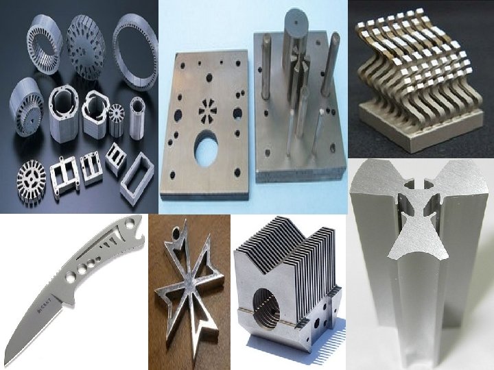
Figure 7 -3 Example of complex parts that were machined on a wire EDM machine.
Cutting With EDM Ø Ø Ø One important attribute: The materials to be cut must be an electrically conductive material. However: In general, The important characteristics 1. cutting speed 2. melting point 3. conductivity of the material 4. length and strength of the electrical pulses Cuts by creating sparks between the wire and the workpiece. Fluid run between the wire and workpiece called dielectric meaning nonconductive act like resistor until enough voltage is applied. The dielectric fluid is normally de-ionized water and a good insulator to avoid short circuit between the wire and the workpiece. Wire wear and cutting rate depend on the characteristic of the workpiece material.
Con’t The flow rate is crucial to efficient, accurate cutting and control by two valve one for top flow and second valves for bottom. Ø The color of sparks also can be used to adjust flow rate: a) Blue sparks are desirable. b) Red sparks indicate an insufficient flow rate. Ø The electrical control on the machine maintains a gap of 0. 001” to 0. 002” between the wire electrode and workpiece. Ø The wire never touches the workpiece. If it did, it would short out /short circuit/wire brakage and the machine would sense it and make a correction. Ø
Type Of Wire EDM Machine - There are three main types of wire EDM. 1. two-axis EDM – simple XY table that can make only simple right-angle cuts. Figure 7 -4 A simple XY machine cut. Note that there is no taper in the hole.
Con’t 2. Simultaneous four-axis EDM – can cut tapers through the workpiece, but the top and bottom of the cut must be the same shape. Example: If the top of the cut is a square, the bottom of the cut must also be a square, although it can be a different size. Figure 7 -5 A workpiece that required a tapered hole. This would require a four-axis wire EDM.
Con’t 3. Independent four-axis system – the top shape and the bottom shape can be different. Has a UV axis guides the wire above the workpiece, and XY axis guides the wire below the workpiece.
Con’t Figure 7 -6 The UV wire guide (top) and the XY wire guide (bottom). Figure 7 -7 A part that requires two cut. The straight cut through the piece would be made first, and then taper would be cut.
Parts Of The Wire-Feed EDM The main parts of a wire-feed EDM are: 1. Bed 2. Saddle 3. Column 4. UV and XY axis 5. Wire-feed system 6. dielectric fluid system 7. machine control
Con’t Ø Wire-feed machines have several servo systems to control various aspects of the machining process. Ø The servo control senses the current and adjusts the drive motors to speed up or slow down to retain the proper gap between wire and workpiece. Ø Sometimes called adaptive control, this control can also adjust the feed rate to compensate for workpiece thickness and changing cutting conditions.
Con’t Important Machining Considerations One of the problems of EDM machining is called recast. Ø This extreme heat on the molecular structure on the surface of the part that is cut. Ø Recast layer is material that has been vaporized and has reattached itself to the remaining material and solidified before it was flushed away. Ø
Con’t Ø The heat-affected zone below these particles is a thin region that was heated to the melting point and then cooled very rapidly. Ø Region can very hard and brittle, which makes it very susceptible to surface cracks because it cools more rapidly than the region below. Ø Works at high current for short on-time cycle, which helps minimize the heat-affected zone. Ø The energy should be reduced on skim cuts (finish cuts), and they should remove the heat-affected zone from the previous pass.
Con’t When machining corners, EDM will leave a sharp edge on the inside of the turn and a radius on the outside of the turn. Ø In the example : Ø Ø The smaller radius possible would be 0. 007”: 0. 006” (radius of the wire) + 0. 001” (the smallest spark gap possible). Ø The wire also tends to deflect in the middle because of the electromagnetic field generated.
Machine Setup Ø Ø Ø The workpiece is clamped to the table, which must be open in the middle to allow the wire to travel through the table. Make sure that the piece that is cut out will not move and short the wire. This could potentially damage the workpiece and/or the machine. The workpiece must be properly aligned on the table. Accurate alignment is fundamental to producing a quality part. The wire tension must then be set using a wire tension gauge (tensiometer). The amount of tension used depends on the type and diameter of the wire.
Con’t Edge Detection Ø Many machine have an automatic edge detection function. Ø The operator locates the wire close to an edge and turns on the wire tension control switch (the wire should be running and the flushing should be on). Ø The operator starts the edge-finding control. The machine move in the direction the operator has been chosen until the control sense continuity (a short circuit) between the wire and the workpiece.
Con’t Hole Location Detection The operator threads the wire trough a hole in the workpiece and aligns the table so that the wire is approximately in the center of the hole. Ø The operator chooses the hole direction mode on the control and turns on the wire tension control switch (the wire should be running and the flushing should be on). Ø The operator chooses a slow feedrate and presses the desired axis button. Ø The machine then begins the hole detection sequence and accurately centers the wire in the hole. Ø
Con’t Slot Location Detection Ø The operator threads the wire through a slot in the workpiece and aligns the table so that the wire is approximately in the center of the slot. Ø The operator chooses the slot-direction mode on the control and turns on the wire tension control switch (the wire should be running and the flushing should be on). Ø The operator chooses a slow feedrate and presses the desired axis button. Ø The machine then begins the slot detection sequence and accurately centers the wire in the slot.
Con’t Test Square The test square program, often run before cutting the actual part, cuts a 0. 100 -inch square. Ø This permits the operator to make any offset adjustments that may be required. Ø It also allows the operator to check the surface finish and make any changes to the cutting conditions before the actual part is cut. Ø
Any Material Can Be Machining by EDM Wire Cut It can machine anything that is electrically conductive regardless of the hardness, from relatively common materials such as tool steel, aluminum, copper, and graphite, to exotic space-age alloys including hastaloy, waspaloy, inconel, titanium, carbide, polycrystalline diamond compacts and conductive ceramics.