Dose Distribution and Scatter Analysis Phantoms Depth Dose

Dose Distribution and Scatter Analysis • • • Phantoms Depth Dose Distribution Percentage Depth Dose Tissue-Air Ratio Scatter-Air Ratio

Phantoms • Water phantom: closely approximates the radiation absorption and scattering properties of muscle and other soft tissues; universally available with reproducible

PHANTOMS • Basic dose distribution data are usually measured in a water phantom, which closely approximates the radiation absorption and scattering properties of muscle and other soft tissue • Another reason for the choice of water as a phantom material is that it is universally available with reproducible radiation properties.

PHANTOMS • Solid dry phantoms – tissue or water equivalent, it must have the same • effective atomic number • number of electrons per gram • mass density – For megavoltage photon beams in the clinical range, the necessary condition for water equivalence • same electron density (number of electrons per Compton effect is the cubic centimeter) main interaction

Solid dry phantoms
 phantoms")
Solid dry (Slab) phantoms

Alderson Rando Phantom • anthropomorphic phantom – Frequently used for clinical dosimetry – Incorporates materials to simulate various body tissues, muscle, bone, lung, and air cavities

RANDO phantom CT slice through lung Head with TLD holes

Depth Dose Distribution • The absorbed dose in the patient varies with depth • The variation depends on depth, field size, distance from source, beam energy and beam collimation • Percentage depth dose, tissue-air ratios, tissuephantom ratios and tissue-maximum ratios--measurements made in water phantoms using small ionization chambers

Percentage Depth Dose • Absorbed dose at any depth: d • Absorbed dose at a fixed reference depth: d 0 collimator surface d 0 d D d 0 Dd phantom
 and lower")
PERCENTAGE DEPTH DOSE • For orthovoltage (up to about 400 k. Vp) and lower -energy x-rays, the reference depth is usually the surface (do = 0). • For higher energies, the reference depth is taken at the position of the peak absorbed dose (do = dm).

Percentage Depth Dose • For higher energies, the reference depth is at the peak absorbed dose ( d 0= d m) • D max : maximum dose, the dose maximum, the given dose collimator surface dm d D max Dd phantom
Dependence on beam quality and depth • (b)Effect of field")
Percentage Depth Dose • (a)Dependence on beam quality and depth • (b)Effect of field size and shape • (c)Dependence on SSD
Dependence on beam quality and depth • Kerma— (1) kinetic energy")
Percentage Depth Dose (a)Dependence on beam quality and depth • Kerma— (1) kinetic energy released per mass in the medium; (2) the energy transferred from photons to directly ionizing electron; (3) maximum at the surface and decreases with depth due to decreased in the photon energy fluence; (4) the production of electrons also decreases with depth
Dependence on beam quality and depth • Absorbed dose: • (1)")
Percentage Depth Dose (a)Dependence on beam quality and depth • Absorbed dose: • (1) depends on the electron fluence; • (2) high-speed electrons are ejected from the surface and subsequent layers; • (3) theses electrons deposit their energy a significant distance away from their site of origin

Fig. 9. 3 central axis depth dose distribution for different quality photon beams
Effect of field size and shape • Geometrical field size: the")
Percentage Depth Dose (b)Effect of field size and shape • Geometrical field size: the projection, on a plane perpendicular to the beam axis, of the distal end of the collimator as seen from the front center of the source • Dosimetric ( Physical ) field size: the distance intercepted by a given isodose curve (usually 50% isodose ) on a plane perpendicular to the beam axis

PDD - Effect of Field Size and Shape • Field size – Geometrical – Dosimetrical or physical SAD FS
Effect of field size and shape • As the field size")
Percentage Depth Dose (b)Effect of field size and shape • As the field size is increased, the contribution of the scattered radiation to the absorbed dose increases • This increase in scattered dose is greater at larger depths than at the depth of D max , the percent depth dose increases with increasing field size Scatter dose Dmax Dd
Effect of field size and shape • Depends on beam quality")
Percentage Depth Dose (b)Effect of field size and shape • Depends on beam quality • The scattering probability or cross-section decreases with energy increase and the higherenergy photons are scattered more predominantly in the forward direction, the field size dependence of PDD is less pronounced for the higher-energy than for the lower-energy beams
Effect of field size and shape • PDD data for radiotherapy")
Percentage Depth Dose (b)Effect of field size and shape • PDD data for radiotherapy beams are usually tabulated for square fields • In clinical practice require rectangular and irregularly shaped fields • A system of equating square fields to different field shapes is required: equivalent square • Quick calculation of the equivalent

c B c rectangular field A square field c=2 x Ax. B A+B
Effect of field size and shape • Quick calculation of the")
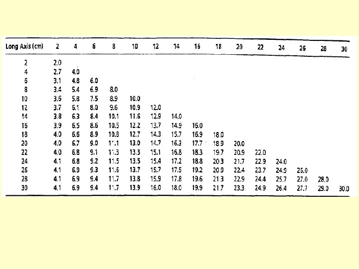
Percentage Depth Dose (b)Effect of field size and shape • Quick calculation of the equivalent field parameters: for rectangular fields • For square fields, since a = b, • the side of an equivalent square of a rectangular field is a b
--(b)Effect of field size and shape • Equivalent circle has the same")
Percentage Depth Dose(3)--(b)Effect of field size and shape • Equivalent circle has the same area as the equivalent square a b r
 dependence on SSD • Photon fluence emitted by a point")
Percentage Depth Dose (c) dependence on SSD • Photon fluence emitted by a point source of radiation varies inversely as a square of the distance from the source • The actual dose rate at a point decreases with increase in distance from the source, the percent depth dose, which is a relative dose, increases with SSD • Mayneord F factor

PDD - Dependence on Source. Surface Distance • Dose rate in free space from a point source varies inversely as the square of the distance. (IVSL) – scattering material in the beam may cause deviation from the inverse square law. • PDD increases with SSD – IVSL SSD’ SSD dm d
 dependence on SSD F 1+dm F 2+dm F 1+d F")
Percentage Depth Dose (c) dependence on SSD F 1+dm F 2+dm F 1+d F 2+d Fig. 9. 5 Plot of relative dose rate as inverse square law function of distance from a point source. Reference distance = 80 cm

f 1 f 2 r dm r d dm d

f 1 f 2 r dm r d dm d PDD increases with SSD the Mayneord F Factor ( without considering changes in scattering )

PDD - Dependence on Source-Surface Distance • PDD increases with SSD

Example The PDD for a 15× 15 field size, 10 -cm depth, and 80 -cm SSD is 58. 4 -Gy (C 0 -60 Beam). Find the PDD for the same field size and depth for a 100 -cm SSD Assuming dm=0. 5 -cm for (C 0 -60 Gamma Rays). F=1. 043 P= 58. 4*1. 043=60. 9
 dependence on SSD • Under extreme conditions such as lower")
Percentage Depth Dose (c) dependence on SSD • Under extreme conditions such as lower energy, large field (the proportion of scattered radiation is relatively greater), large depth, and large SSD, the Mayneord F factor is significant errors • In general, the Mayneord F factor overestimates the increase in PDD with increase in SSD

PDD - Dependence on Source-Surface Distance • PDD increases with SSD – the Mayneord F Factor • works reasonably well for small fields since the scattering is minimal under these conditions. • However, the method can give rise to significant errors under extreme conditions such as lower energy, large field, large depth, and large SSD change.
 at a")
Tissue-Air ratio • The ratio of the dose ( D d ) at a given point in the phantom to the dose in free space ( D f s ) • TAR depends on depth d and field size rd at the depth: (BSF) Equilibrium mass phantom d rd rd Dd D fs
 Effect of Distance • Independent of the distance from")
Tissue-Air ratio ( a ) Effect of Distance • Independent of the distance from the source • The TAR represents modification of the dose at a point owing only to attenuation and scattering of the beam in the phantom compared with the dose at the same point in the miniphantom ( or equilibrium phantom ) placed in free air
 Variation with energy, depth, and field size • For")
Tissue-Air ratio ( b ) Variation with energy, depth, and field size • For the megavoltage beams, the TAR builds up to a maximum at the d m and then decreases with depth • As the field size is increased, the scattered component of the dose increases and the variation of TAR with depth becomes more complex
 Variation with energy, depth, and field size: BSF •")
Tissue-Air ratio ( b ) Variation with energy, depth, and field size: BSF • Backscatter factor (BSF) depends only on the beam quality and field size • Above 8 MV, the scatter at the depth of Dmax becomes negligibly small and the BSF approaches its minimum value of unity

Fig. 9. 8 Variation of backscatter factors with beam quality

The meaning of Backscatter factor • For example, BSF for a 10 x 10 cm field for 60 Co is 1. 036 means that D max will be 3. 6% higher than the dose in free space • This increase in dose is the result of radiation scatter reaching the point of D max from the overlying and underlying tissues
 relationship between TAR and PDD")
Tissue-Air ratio ( c ) relationship between TAR and PDD
 relationship between TAR and PDD-- Conversion of PDD from")
Tissue-Air ratio ( c ) relationship between TAR and PDD-- Conversion of PDD from one SSD to another : The TAR method Burns’s equation:
 calculation of dose in rotation therapy d=16. 6")
Tissue-Air ratio ( d ) calculation of dose in rotation therapy d=16. 6
 • Calculating scattered dose in the medium • The ratio of the")
Scatter-Air Ratio(SAR) • Calculating scattered dose in the medium • The ratio of the scattered dose at a given point in the phantom to the dose in free space at the same point • TAR(d, 0): the primary component of the beam Equilibrium mass phantom d rd rd Dd D fs

Scatter-Air Ratio--Dose calculation in irregular fields: Clarkson’s Method Based on the principle that the scattered component of the depth dose can be calculated separately from the primary component Average tissue-air ratio Average scatter-air ratio TAR ( 0 ) = tissue-air ratio for 0 x 0 field
- Slides: 45