
Distributed Energy Systems Ali Keyhani Professor of Electrical
Distributed Energy Systems Ali Keyhani Professor of Electrical and Computer Engineering Keyhani. 1@OSU. edu Amirkabir University of Technology, May 18 , 2004, Tehran, Iran Mechatronic Systems Laboratory Department of Electrical and Computer Engineering The Ohio State University 1 Mechatronics Lab.
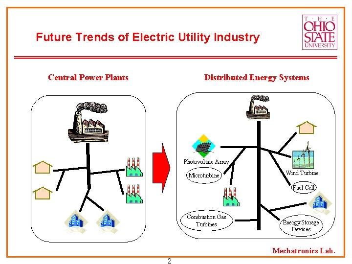
Future Trends of Electric Utility Industry Central Power Plants Distributed Energy Systems Photovoltaic Array Microturbine Wind Turbine Fuel Cell Combustion Gas Turbines Energy Storage Devices Mechatronics Lab. 2
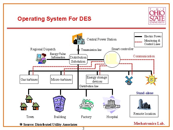
Operating System For DES Electric Power Monitoring & Control Lines Central Power Station Transmission line Regional Dispatch Energy Value Information Gas turbines Smart controller Communication Distribution Substation Energy storage devices Micro-turbines Distribution line Stand-alone Town Building Source: Distributed Utility Associates Factory Hospital Remote location Mechatronics Lab. 3
Technologies for DES n Technologies for Distributed Energy Systems (DES) Ø Gas technologies Combustion gas turbines Micro-turbines Fuel cells Ø Renewable Energy Technologies Biomass power Small wind turbines Photovoltaic Arrays Ø Energy Storage Devices Battery Flywheel Superconducting Magnetic Energy Storage (SMES) Ultracapacitor (Supercapacitor) Compressed Air Energy Storage (CAES) 4 Mechatronics Lab.
Applications for DES n Applications of DES Ø Stand-alone Ø Standby Ø Grid-interconnected Ø Cogeneration (Combined Heat and Power (CHP)) Ø Peak shaving Mechatronics Lab. 5
Benefits of DES n Benefits of DES Ø Environmental-friendly and modular electric generation Ø Increased reliability/stability Ø High power quality Ø Load management Ø Fuel flexibility Ø Uninterruptible service Ø Cost savings Ø On-site generation Ø Expandability Mechatronics Lab. 6
Barriers of DES n Barriers Ø Technical Barriers Protective equipment Safety measures Reliability and power-quality concerns Ø Business-Practices Barriers Contractual and procedural requirements for interconnection Procedures for approving interconnection, application and interconnection fees, Insurance requirements Operational requirements Ø Regulatory Barriers Tariff structures applicable to customers Backup or standby charges Net metering Environmental permitting Mechatronics Lab. 7
What supports Technologies of DES? n What supports Technologies of DES? Ø Power Electronics Technologies Advanced Power Converter Design Technique High-speed/high-power/low-losses power switches New control techniques Digital signal processors with high performance Ø New communications in the form of the Internet Ø Planning and valuation tools Value to grid Capacity needs assessment Mechatronics Lab. 8
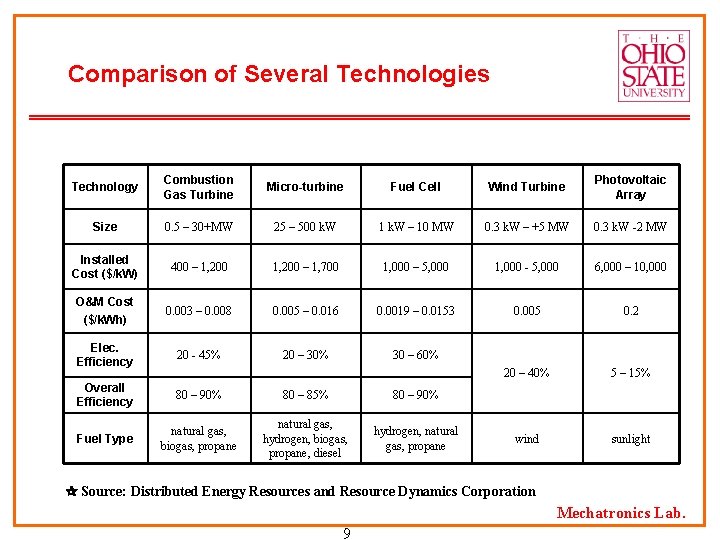
Comparison of Several Technologies Technology Combustion Gas Turbine Micro-turbine Fuel Cell Wind Turbine Photovoltaic Array Size 0. 5 – 30+MW 25 – 500 k. W 1 k. W – 10 MW 0. 3 k. W – +5 MW 0. 3 k. W -2 MW Installed Cost ($/k. W) 400 – 1, 200 – 1, 700 1, 000 – 5, 000 1, 000 - 5, 000 6, 000 – 10, 000 O&M Cost ($/k. Wh) 0. 003 – 0. 008 0. 005 – 0. 016 0. 0019 – 0. 0153 0. 005 0. 2 Elec. Efficiency 20 - 45% 20 – 30% 30 – 60% 20 – 40% 5 – 15% Overall Efficiency 80 – 90% 80 – 85% 80 – 90% Fuel Type natural gas, biogas, propane natural gas, hydrogen, biogas, propane, diesel hydrogen, natural gas, propane wind sunlight Source: Distributed Energy Resources and Resource Dynamics Corporation Mechatronics Lab. 9
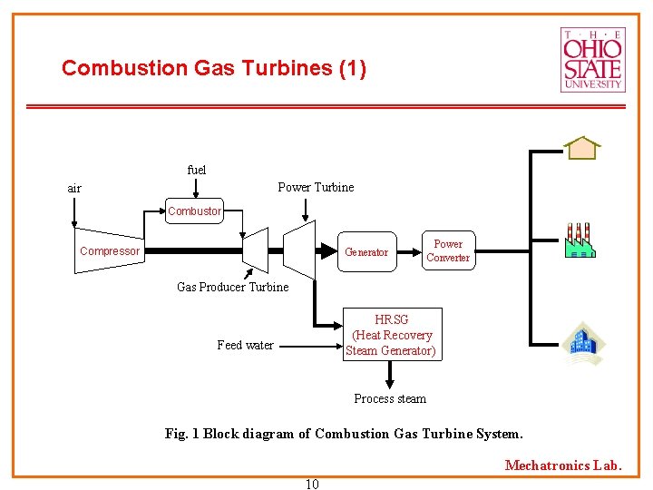
Combustion Gas Turbines (1) fuel Power Turbine air Combustor Compressor Generator Power Converter Gas Producer Turbine HRSG (Heat Recovery Steam Generator) Feed water Process steam Fig. 1 Block diagram of Combustion Gas Turbine System. Mechatronics Lab. 10
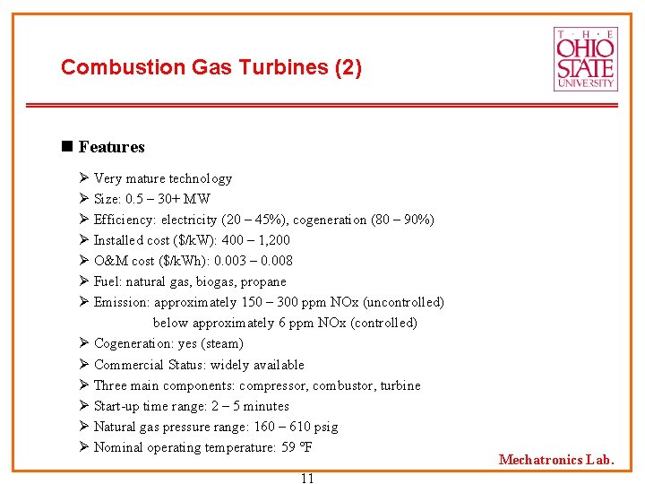
Combustion Gas Turbines (2) n Features Ø Very mature technology Ø Size: 0. 5 – 30+ MW Ø Efficiency: electricity (20 – 45%), cogeneration (80 – 90%) Ø Installed cost ($/k. W): 400 – 1, 200 Ø O&M cost ($/k. Wh): 0. 003 – 0. 008 Ø Fuel: natural gas, biogas, propane Ø Emission: approximately 150 – 300 ppm NOx (uncontrolled) below approximately 6 ppm NOx (controlled) Ø Cogeneration: yes (steam) Ø Commercial Status: widely available Ø Three main components: compressor, combustor, turbine Ø Start-up time range: 2 – 5 minutes Ø Natural gas pressure range: 160 – 610 psig Ø Nominal operating temperature: 59 F 11 Mechatronics Lab.
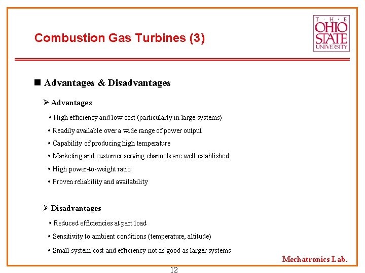
Combustion Gas Turbines (3) n Advantages & Disadvantages Ø Advantages High efficiency and low cost (particularly in large systems) Readily available over a wide range of power output Capability of producing high temperature Marketing and customer serving channels are well established High power-to-weight ratio Proven reliability and availability Ø Disadvantages Reduced efficiencies at part load Sensitivity to ambient conditions (temperature, altitude) Small system cost and efficiency not as good as larger systems Mechatronics Lab. 12
Combustion Gas Turbines (4) n Future Research Issues Ø 10 – 20% cost lower than conventional power systems Ø Break the 60% barrier in net thermal efficiency Ø Reduce Sox and NOx emissions Ø Development of next generation turbine system for product commercialization in 2002 and market entry around 2008 n Vendors Alstom, General Electric Power Systems, IHI, Kawasaki Gas Turbines-Americas, Pacific Power Solutions, Pratt & Whitney, Rolls-Royce, Siemens Westinghouse Power Corporation, Solar, Vericor Power Systems Mechatronics Lab. 13
Micro-turbines (2) n Features Ø Size: 25 – 500 k. W Ø Efficiency: unrecuperated (15%), recuperated (20 – 30%), with heat recovery (up to 85%) Ø Installed cost ($/k. W): 1, 200 – 1, 700 Ø O&M cost ($/k. Wh): 0. 005 – 0. 016 Ø Fuel: natural gas, hydrogen, biogas, propane, diesel Ø Emission: below approximately 9 - 50 ppm NOx Ø Cogeneration: yes (50 – 80 C water) Ø Commercial Status: small volume production, commercial prototypes now Ø Rotating speed: 90, 000 – 120, 000 Ø Maintenance interval: 5, 000 – 8, 000 hrs Mechatronics Lab. 15
Micro-turbines (3) n Advantages & Disadvantages Ø Advantages Small number of moving parts Compact size Light-weight Good efficiencies in cogeneration Low emissions Can utilize waste fuels Long maintenance intervals Ø Disadvantages Low fuel to electricity efficiencies Loss of power output and efficiency with higher ambient temperatures and elevation Mechatronics Lab. 16
Micro-turbines (4) n Future Research Issues Ø Improve the micro-turbine design Ø Lowering costs Ø Increasing performance Ø Heat recovery/cogeneration Ø Fuel flexibility Ø Vehicles Ø Hybrid systems (e. g. , fuel cell/micro-turbine, flywheel/micro-turbine) n Vendors Bowman Power Systems, Capstone Turbine Corporation, Elliott Energy Systems, Ingersoll Rand Energy Systems, Turbec AB Mechatronics Lab. 17
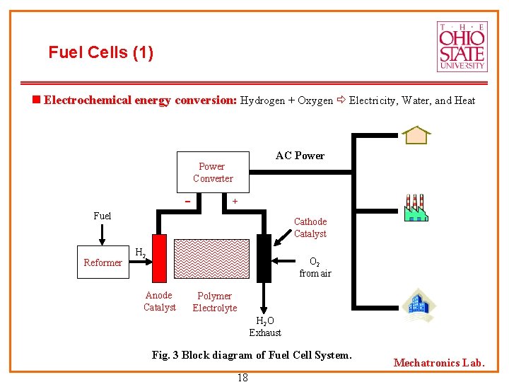
Fuel Cells (1) Electrochemical energy conversion: Hydrogen + Oxygen Electricity, Water, and Heat AC Power Converter + Fuel Reformer Cathode Catalyst H 2 O 2 from air Anode Catalyst Polymer Electrolyte H 2 O Exhaust Fig. 3 Block diagram of Fuel Cell System. 18 Mechatronics Lab.
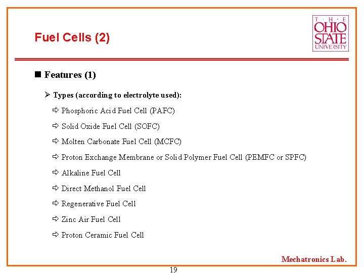
Fuel Cells (2) n Features (1) Ø Types (according to electrolyte used): Phosphoric Acid Fuel Cell (PAFC) Solid Oxide Fuel Cell (SOFC) Molten Carbonate Fuel Cell (MCFC) Proton Exchange Membrane or Solid Polymer Fuel Cell (PEMFC or SPFC) Alkaline Fuel Cell Direct Methanol Fuel Cell Regenerative Fuel Cell Zinc Air Fuel Cell Proton Ceramic Fuel Cell Mechatronics Lab. 19
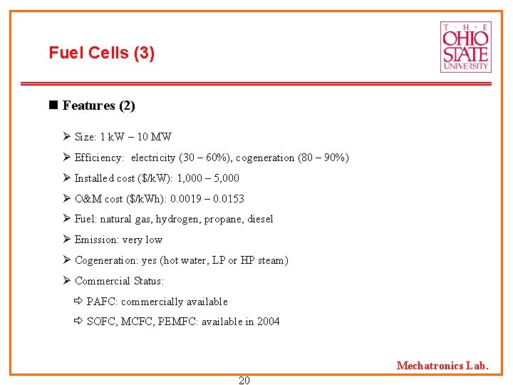
Fuel Cells (3) n Features (2) Ø Size: 1 k. W – 10 MW Ø Efficiency: electricity (30 – 60%), cogeneration (80 – 90%) Ø Installed cost ($/k. W): 1, 000 – 5, 000 Ø O&M cost ($/k. Wh): 0. 0019 – 0. 0153 Ø Fuel: natural gas, hydrogen, propane, diesel Ø Emission: very low Ø Cogeneration: yes (hot water, LP or HP steam) Ø Commercial Status: PAFC: commercially available SOFC, MCFC, PEMFC: available in 2004 Mechatronics Lab. 20
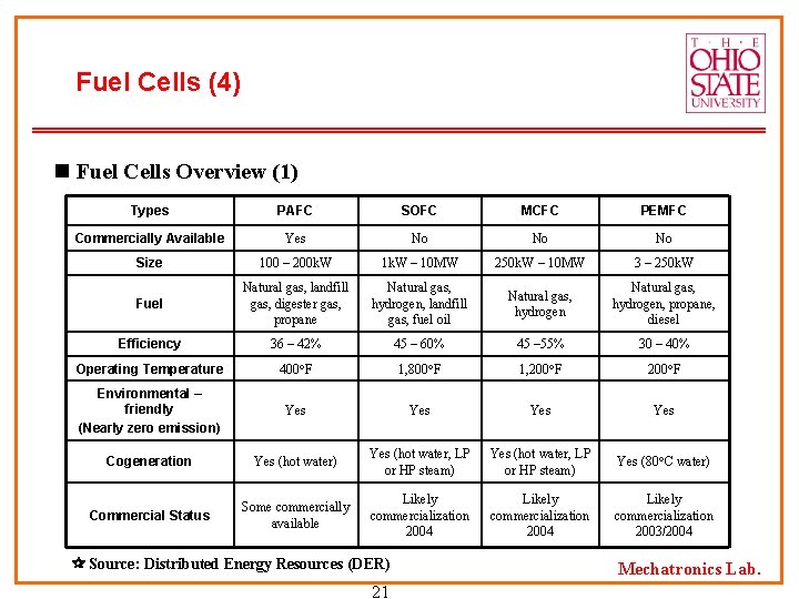
Fuel Cells (4) n Fuel Cells Overview (1) Types PAFC SOFC MCFC PEMFC Commercially Available Yes No No No Size 100 – 200 k. W 1 k. W – 10 MW 250 k. W – 10 MW 3 – 250 k. W Fuel Natural gas, landfill gas, digester gas, propane Natural gas, hydrogen, landfill gas, fuel oil Natural gas, hydrogen, propane, diesel Efficiency 36 – 42% 45 – 60% 45 – 55% 30 – 40% Operating Temperature 400 F 1, 800 F 1, 200 F Environmental – friendly (Nearly zero emission) Yes Yes Cogeneration Yes (hot water) Yes (hot water, LP or HP steam) Yes (80 C water) Commercial Status Some commercially available Likely commercialization 2004 Likely commercialization 2003/2004 Source: Distributed Energy Resources (DER) 21 Mechatronics Lab.
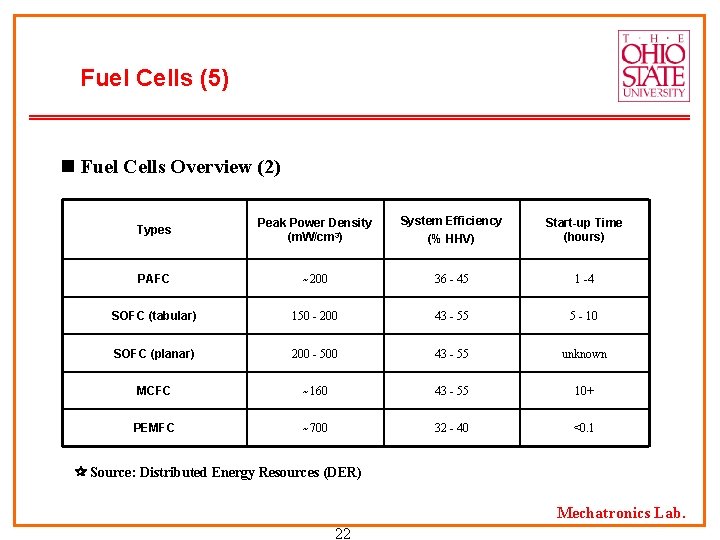
Fuel Cells (5) n Fuel Cells Overview (2) Types Peak Power Density (m. W/cm 3) System Efficiency (% HHV) Start-up Time (hours) PAFC ~200 36 - 45 1 -4 SOFC (tabular) 150 - 200 43 - 55 5 - 10 SOFC (planar) 200 - 500 43 - 55 unknown MCFC ~160 43 - 55 10+ PEMFC ~700 32 - 40 <0. 1 Source: Distributed Energy Resources (DER) Mechatronics Lab. 22
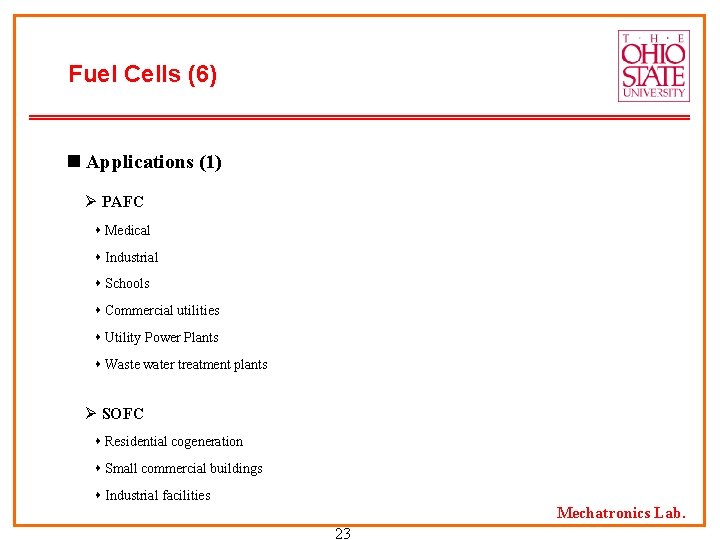
Fuel Cells (6) n Applications (1) Ø PAFC Medical Industrial Schools Commercial utilities Utility Power Plants Waste water treatment plants Ø SOFC Residential cogeneration Small commercial buildings Industrial facilities Mechatronics Lab. 23
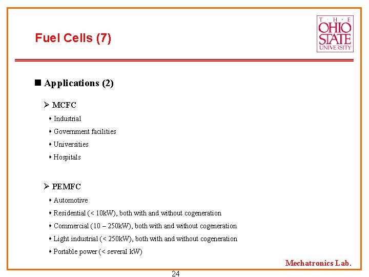
Fuel Cells (7) n Applications (2) Ø MCFC Industrial Government facilities Universities Hospitals Ø PEMFC Automotive Residential (< 10 k. W), both with and without cogeneration Commercial (10 – 250 k. W), both with and without cogeneration Light industrial (< 250 k. W), both with and without cogeneration Portable power (< several k. W) Mechatronics Lab. 24
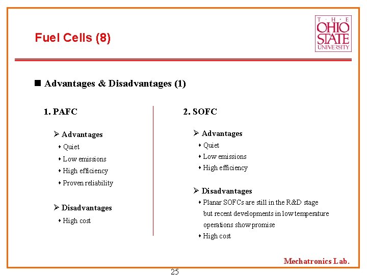
Fuel Cells (8) n Advantages & Disadvantages (1) 1. PAFC 2. SOFC Ø Advantages Quiet Low emissions High efficiency Proven reliability Ø Disadvantages Planar SOFCs are still in the R&D stage Ø Disadvantages but recent developments in low temperature High cost operations show promise High cost Mechatronics Lab. 25
Fuel Cells (9) n Advantages & Disadvantages (2) 3. MCFC 4. PEMFC Ø Advantages Quiet Low emissions High efficiency Synergy with automotive Ø Disadvantages Need to demonstrate long term dependability High cost Ø Disadvantages Limited field test experience Low temperature waste heat may limit cogeneration potential High cost Mechatronics Lab. 26
Fuel Cells (10) n Future Research Issues (1) 1. PAFC Ø Increase anode CO tolerance with operating temperature : Simplify reformer design, and increase the lifetime of reformate-fueled stacks Ø Lower the moderate stack temperature to allow rapid start-up and shutdown Ø Increase the temperature difference between the stack and the environment thermal and water management functions of the fuel cell system are greatly simplified Ø Decrease the system water requirements and increase the flexibility of operation Mechatronics Lab. 27
Fuel Cells (11) n Future Research Issues (2) 2. SOFC Ø Cost reduction Ø Identify configurations to require less stringent material purity specifications Ø Identify routes to reduce the amount of insulation in the system Ø Move manufacturing processes towards net-forming rather than machining in order to minimize scrap production Ø Use of less exotic alloys Ø Maintenance of seals and manifolds under severe thermal stresses Ø Long-term mechanical integrity of planar systems Ø Long-term material compatibility of planar systems Mechatronics Lab. 28
Fuel Cells (12) n Future Research Issues (3) 3. MCFC Ø Extend stack life Ø Increase the power density Ø Reduce the cost 4. PEMFC Ø Operate at pressures > 1. 5 atm. Ø Guarantee long-term operation Ø Produce 10 – 20 ppm CO in long-term, real-world environments Ø Operation of fully integrated systems in a broad range of thermal environments with adequate water recovery over extended periods Ø Operation of fully integrated systems in environments like freezing temperatures Mechatronics Lab. 29
Fuel Cells (13) n Vendors Ø Phosphoric Acid Fuel Cell (PAFC) Japan’s Fuji Electric Company, Ltd. , UTC Fuel Cells, Mitsubishi Electric Corporation Ø Solid Oxide Fuel Cell (SOFC) Global Thermoelectric, Siemens Westinghouse Power Corporation, SOFCo, ZTEK Corporation Ø Molten Carbonate Fuel Cell (MCFC) Fuel Cell Energy, Hitachi, Ltd. , Ansaldo Ricerche Srl Ø Proton Exchange Membrane Fuel Cell (PEMFC) Avista Labs, Ballard Generation Systems, Dais-Analytic Corporation, H Power, Ida. Tech, UTC Fuel Cells, Nuvera Fuel Cells, Plug Power, Proton Energy Systems Mechatronics Lab. 30
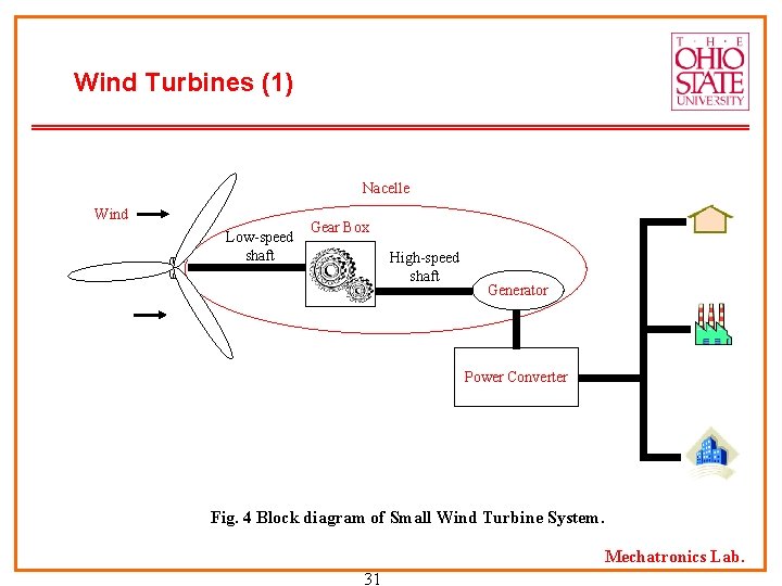
Wind Turbines (1) Nacelle Wind Low-speed shaft Gear Box High-speed shaft Generator Power Converter Fig. 4 Block diagram of Small Wind Turbine System. Mechatronics Lab. 31
Wind Turbines (2) n Features Ø Size: small (0. 3 - 50 k. W), large (300 k. W – +5 MW) Ø Efficiency: 20 – 40% Ø Installed cost ($/k. W): large-scale (900 - 1, 100), small-scale (2, 500 - 5, 000) Ø O&M cost ($/k. Wh): 0. 005 Ø Fuel: wind Ø Emission: zero Ø Other features: various types and sizes Ø Commercial Status: widely available Ø Wind speed: Large turbine: 6 m/s (13 mph) at average sites Small turbine: 4 m/s (9 mph) at average sites Ø Typical life of a wind turbine: 20 years Mechatronics Lab. 32
Wind Turbines (3) n Advantages & Disadvantages Ø Advantages Power generated from wind farms can be inexpensive Low cost energy No harmful emissions Minimal land use : the land below each turbine can be used for animal grazing or farming No fuel required Ø Disadvantages Variable power output due to the fluctuation in wind speed Location limited Visual impact : Aesthetic problem of placing them in higher population density areas Bird mortality Mechatronics Lab. 33
Wind Turbines (4) n Future Research Issues Ø Lower the cost of energy from wind to 2. 5 cents/k. Wh at sites with 6. 7 m/s [15 mph] winds Ø Reduce system cost Ø Improve efficiency of wind turbine generator Ø Improve power quality Ø New design of the airfoils for the wind turbine blades n Vendors Atlantic Orient Corporation, Bergey Wind. Power Company, Inc. , Enron Wind, Northern Power Systems, Southwest Windpower Inc. , Vestas-American Wind Technology, Inc. Mechatronics Lab. 34
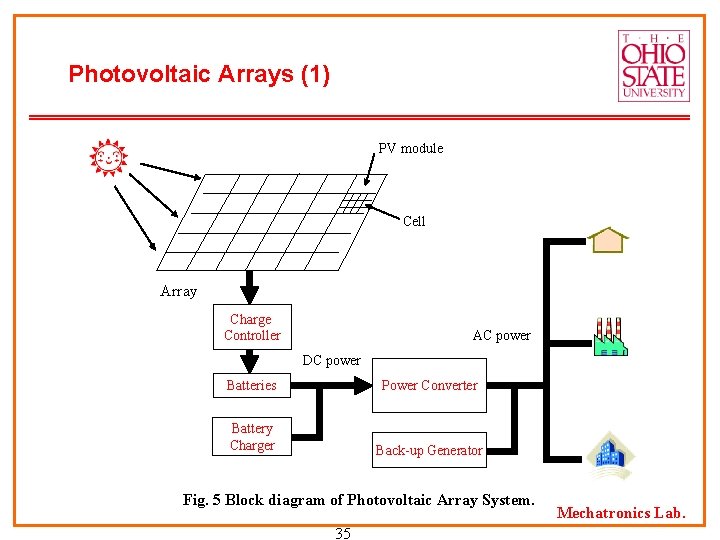
Photovoltaic Arrays (1) PV module Cell Array Charge Controller AC power DC power Batteries Power Converter Battery Charger Back-up Generator Fig. 5 Block diagram of Photovoltaic Array System. 35 Mechatronics Lab.
Photovoltaic Arrays (2) n Features (1) Ø Several types of solar electric technology (1): Crystalline silicon: Used in more than half of all solar electric devices Consists of a positive (p-type) layer and a negative (n-type) layer Applications: Small (watch, calculator), Large (satellites, electricity for utilities) Thin films: Lighter, more resilient, and easier to manufacture than crystalline silicon module Materials used: amorphous silicon (best), cadmium telluride, and copper indium diselenide Cost saving because of relatively little semiconductor materials Flexible solar electric roofing shingles Mechatronics Lab. 36
Photovoltaic Arrays (3) n Features (2) Ø Several types of solar electric technology (2): Concentrators: Need optical lenses or mirrors to concentrate the sunlight Components: a lens, a solar cell assembly, a housing element, a secondary concentrator, various contacts and adhesives Materials used: crystalline silicon, gallium arsenide, and gallium indium phosphide Cost saving because of using inexpensive semiconductor materials Thermophotovoltaics (TPV) Convert heat into electricity Advantages: cleaner, quieter, simpler, relatively maintenance free Mechatronics Lab. 37
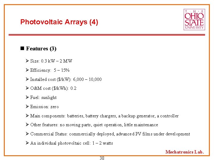
Photovoltaic Arrays (4) n Features (3) Ø Size: 0. 3 k. W – 2 MW Ø Efficiency: 5 – 15% Ø Installed cost ($/k. W): 6, 000 – 10, 000 Ø O&M cost ($/k. Wh): 0. 2 Ø Fuel: sunlight Ø Emission: zero Ø Main components: batteries, battery chargers, a backup generator, a controller Ø Other features: no moving parts, quiet operation, little maintenance Ø Commercial Status: commercially deployed, advanced PV films under development Ø An individual photovoltaic cell: 1 – 2 watts Mechatronics Lab. 38
Photovoltaic Arrays (5) n Advantages & Disadvantages Ø Advantages Work well for remote locations Require very little maintenance Environmentally friendly (No emissions) Ø Disadvantages Local weather patterns and sun conditions directly affect the potential of photovoltaic system. Some locations will not be able to use solar power Mechatronics Lab. 39
Photovoltaic Arrays (6) n Future Research Issues Ø Use of a concentrator technology to concentrate the solar energy over a large area onto a small area of solar cells Ø Increase energy density several hundred times using a freznel lens or reflective surface Ø Use of more exotic solar cell technology for greater efficiency Ø Lower an overall cost/watt competitive with flat plate technologies Ø Increase concentrator efficiency to above 30 % n Vendors Astro. Power, Baekert ECD Solar Systems LLC, BP Solar, Day. Star Technologies, Inc. , Solec international, Inc. , Xantrex Technology, Inc. Mechatronics Lab. 40
Energy Storage Devices (1) n Energy storage technologies To provide electric power over short periods of time To improve the efficiency and reliability of the electric utility system To accelerate adoption of renewable energy technologies To correct voltage sags, flicker, and surges To be used as an Uninterruptible Power Supply (UPS) n Types of Energy Storage Devices Ø Batteries Ø Flywheels Ø Superconducting Magnetic Energy Storage (SMES) Ø Ultracapacitor (Supercapacitor) Ø Compressed Air Energy Storage (CAES) Mechatronics Lab. 41
Energy Storage Devices (2) n Features (1) Ø Batteries To provide an interruptible supply of electricity to power substation To start backup power systems during power outage To increase power quality and reliability Size: 0. 14 – 2, 100 k. VA Operating time: 5 – 60 minutes Types: lead-acid (commercially available and widely used), sodium/sulfur, zinc/bromine, lithium/air Uninterruptible Power Supply (UPS): Cost of a complete UPS system: $200/k. VA - $1, 500/k. VA Battery cost of the complete UPS system: 60 – 70% Battery replacement frequency: every 5 – 7 years Mechatronics Lab. 42
Energy Storage Devices (3) n Features (2) Ø Flywheels Electromechanical device: an integral motor/generator provides power for short durations such as a power outage, voltage sag, or other disturbance Size: 120 – 700 k. W Operating time: 20 sec – 10 minutes RPM: a few thousand – 60, 000 Main components: flywheel, inverter, control system Commercial Status: commercially available as individual products or integrated with prime movers such as engine Mechatronics Lab. 43
Energy Storage Devices (4) n Features (3) Ø Superconducting Magnetic Energy Storage (SMES) To store energy in the field of a large magnetic coil with DC flowing To be used for short durations such as utility switching events Main components: SMES, inverter, control system Commercial Status: low temperature SMES cooled by liquid helium (commercially available) high temperature SMES cooled by liquid nitrogen (in development) Mechatronics Lab. 44
Energy Storage Devices (5) n Features (4) Ø Ultracapacitor To provide power during short duration interruptions and power sags The life of the batteries can be extended if a ultracapacitor is combined with a battery-based UPS system Commercial Status: small ultracapacitor (commercially available) large ultracapacitor (in development) Ø Compressed Air Energy Storage (CAES) To use pressurized air as the energy storage medium An electric motor-driven compressor and a modified turbine required Ideal location for CAES: aquifers, conventional mines in hard rock, hydraulically mined salt caverns Not widely utilized because of the significant space requirements Mechatronics Lab. 45
Energy Storage Devices (6) n Advantages & Disadvantages Ø Advantages Improved power quality and reliability (“premium power”) “Green power” dispatch/purchase options Reduced sizing of distributed generation systems Energy/demand cost saving from load leveling Decreased transmission and distribution infrastructure investment Ø Disadvantages High cost for long duration storage system Parasite power losses to keep unit charge High maintenance (e. g. frequent testing, charge assessment for batteries ) Mechatronics Lab. 46
Energy Storage Devices (7) n Future Research Issues Ø Lower costs Ø Longer life-time Ø Higher efficiency n Vendors Ø Batteries Energizer, Evonyx, Inc. , Ovonic Battery Company, Panasonic Industrial Company, Sony Corporation, Ultralife Batteries, Inc. Ø Flywheels Active Power, AFS Trinity, Beacon Power, Pentadyne, Precise Power Systems Ø Superconducting Magnetic Energy Storage (SMES) American Superconductor Ø Compressed Air Energy Storage (CAES) CAES Development Company LLC Ø Ultracapacitors Power. Cache (Maxwell Technologies, Inc. ), EPRI PEAC 47 Mechatronics Lab.
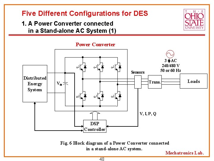
Five Different Configurations for DES 1. A Power Converter connected in a Stand-alone AC System (1) Power Converter 3 AC 240/480 V 50 or 60 Hz Sensors Distributed Energy System Trans. Vdc Loads V, I, P, Q DSP Controller Fig. 6 Block diagram of a Power Converter connected in a stand-alone AC system. Mechatronics Lab. 48
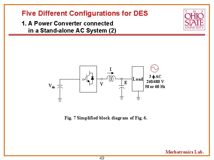
Five Different Configurations for DES 1. A Power Converter connected in a Stand-alone AC System (2) I Vdc V E Load 3 AC 240/480 V 50 or 60 Hz Fig. 7 Simplified block diagram of Fig. 6. Mechatronics Lab. 49
Five Different Configurations for DES 1. A Power Converter connected in a Stand-alone AC System (3) Research Issues (Focus on Power Electronics) Ø Autonomous power system Voltage, power quality and reliability requirements of the customers Ø Power factor correction Elimination of harmonic current and voltage components Compensation of the reactive power and harmonic load current components P and Q controls independently Ø Stability of frequency and voltage according to suddenly additional loads Mechatronics Lab. 50
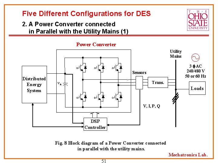
Five Different Configurations for DES 2. A Power Converter connected in Parallel with the Utility Mains (1) Power Converter Utility Mains 3 AC 240/480 V 50 or 60 Hz Sensors Distributed Energy System Trans. Vdc Loads V, I, P, Q DSP Controller Fig. 8 Block diagram of a Power Converter connected in parallel with the utility mains. Mechatronics Lab. 51
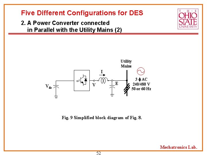
Five Different Configurations for DES 2. A Power Converter connected in Parallel with the Utility Mains (2) Utility Mains I Vdc E V 3 AC 240/480 V 50 or 60 Hz Fig. 9 Simplified block diagram of Fig. 8. Mechatronics Lab. 52
Five Different Configurations for DES 2. A Power Converter connected in Parallel with the Utility Mains (3) Research Issues (Focus on Power Electronics) Ø Distributed system control System protection: overcurrent, overvoltage, undervoltage Seamless connection and isolation from the utility grids Ø Autonomous power system Voltage, power quality and reliability requirements of the customer Ø Power factor correction P and Q controls independently Compensation of the reactive power and harmonic load current components Mechatronics Lab. 53
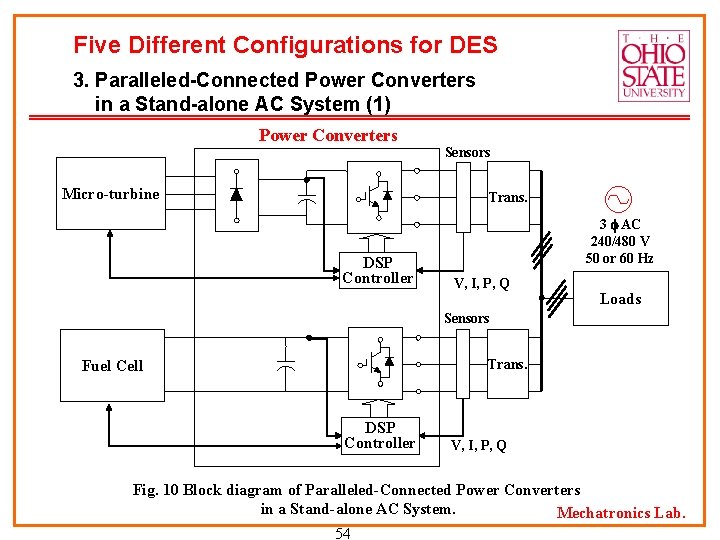
Five Different Configurations for DES 3. Paralleled-Connected Power Converters in a Stand-alone AC System (1) Power Converters Micro-turbine Sensors Trans. DSP Controller 3 AC 240/480 V 50 or 60 Hz V, I, P, Q Loads Sensors Trans. Fuel Cell DSP Controller V, I, P, Q Fig. 10 Block diagram of Paralleled-Connected Power Converters in a Stand-alone AC System. Mechatronics Lab. 54
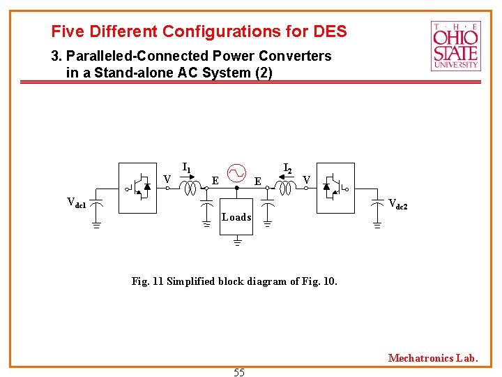
Five Different Configurations for DES 3. Paralleled-Connected Power Converters in a Stand-alone AC System (2) V I 1 E E I 2 V Vdc 1 Loads Vdc 2 Fig. 11 Simplified block diagram of Fig. 10. Mechatronics Lab. 55
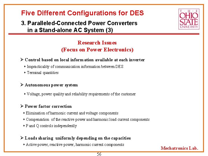
Five Different Configurations for DES 3. Paralleled-Connected Power Converters in a Stand-alone AC System (3) Research Issues (Focus on Power Electronics) Ø Control based on local information available at each inverter Impracticality of communication information between DES Terminal quantities Ø Autonomous power system Voltage, power quality and reliability requirements of the customer Ø Power factor correction Elimination of harmonic current and voltage components Compensation of the reactive power and harmonic load current components P and Q controls independently Ø Loads sharing uniformly depending on the capacities Active power, reactive power, harmonic current components 56 Mechatronics Lab.
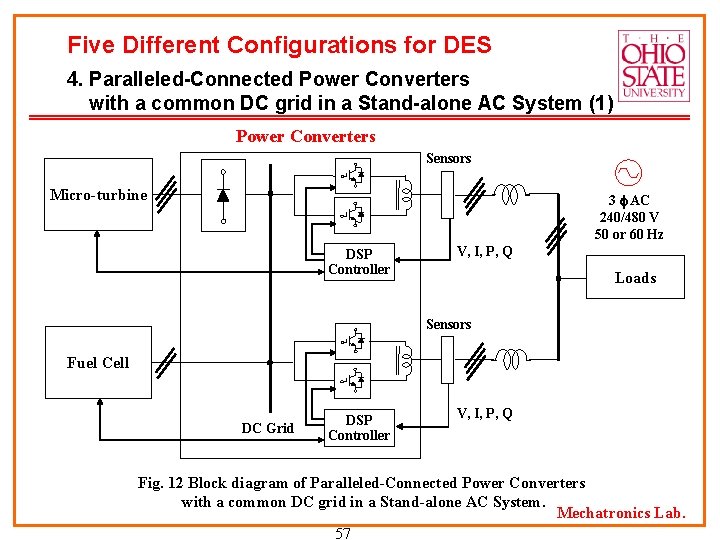
Five Different Configurations for DES 4. Paralleled-Connected Power Converters with a common DC grid in a Stand-alone AC System (1) Power Converters Sensors Micro-turbine 3 AC 240/480 V 50 or 60 Hz DSP Controller V, I, P, Q Loads Sensors Fuel Cell DC Grid DSP Controller V, I, P, Q Fig. 12 Block diagram of Paralleled-Connected Power Converters with a common DC grid in a Stand-alone AC System. Mechatronics Lab. 57
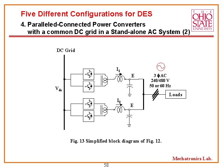
Five Different Configurations for DES 4. Paralleled-Connected Power Converters with a common DC grid in a Stand-alone AC System (2) DC Grid I 1 E Vdc 3 AC 240/480 V 50 or 60 Hz Loads I 2 E Fig. 13 Simplified block diagram of Fig. 12. Mechatronics Lab. 58
Five Different Configurations for DES 4. Paralleled-Connected Power Converters with a common DC grid in a Stand-alone AC System (3) Research Issues (Focus on Power Electronics) Ø Efficient control of the batteries for the long service life Ø Control based on local information available at each inverter Impracticality of communication information between DES Terminal quantities Ø Power factor correction Elimination of harmonic current and voltage components Compensation of the reactive power and harmonic load current components P and Q controls independently Ø Loads sharing uniformly depending on the capacities Active power, reactive power, harmonic current components 59 Mechatronics Lab.
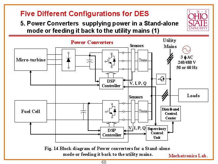
Five Different Configurations for DES 5. Power Converters supplying power in a Stand-alone mode or feeding it back to the utility mains (1) Power Converters Micro-turbine Utility Mains Sensors 3 AC 240/480 V 50 or 60 Hz Trans. DSP Controller V, I, P, Q Loads Sensors Fuel Cell Trans. DSP Controller Distributed Control Center V, I, P, Q Supervisory Control Unit Fig. 14 Block diagram of Power converters for a Stand-alone mode or feeding it back to the utility mains. Mechatronics Lab. 60
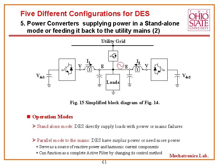
Five Different Configurations for DES 5. Power Converters supplying power in a Stand-alone mode or feeding it back to the utility mains (2) Utility Grid V I 1 E E I 2 V Vdc 1 Vdc 2 Loads Fig. 15 Simplified block diagram of Fig. 14. n Operation Modes Ø Stand alone mode: DES directly supply loads with power or mains failures Ø Parallel mode to the mains: DES have surplus power or need more power Serve as a source of reactive power and harmonic current components Can function as a complete Active Filter by changing its control method 61 Mechatronics Lab.
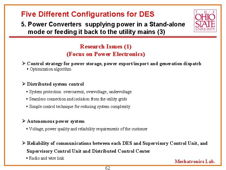
Five Different Configurations for DES 5. Power Converters supplying power in a Stand-alone mode or feeding it back to the utility mains (3) Research Issues (1) (Focus on Power Electronics) Ø Control strategy for power storage, power export/import and generation dispatch Optimization algorithm Ø Distributed system control System protection: overcurrent, overvoltage, undervoltage Seamless connection and isolation from the utility grids Simple control technique for reducing system complexity Ø Autonomous power system Voltage, power quality and reliability requirements of the customer Ø Reliability of communications between each DES and Supervisory Control Unit, and Supervisory Control Unit and Distributed Control Center Radio and wire link Mechatronics Lab. 62
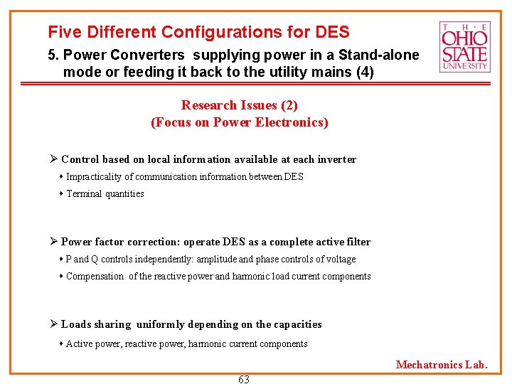
Five Different Configurations for DES 5. Power Converters supplying power in a Stand-alone mode or feeding it back to the utility mains (4) Research Issues (2) (Focus on Power Electronics) Ø Control based on local information available at each inverter Impracticality of communication information between DES Terminal quantities Ø Power factor correction: operate DES as a complete active filter P and Q controls independently: amplitude and phase controls of voltage Compensation of the reactive power and harmonic load current components Ø Loads sharing uniformly depending on the capacities Active power, reactive power, harmonic current components Mechatronics Lab. 63
• Load Management Techniques • Methods of Implementation • Integrated Load Management and Solar Energy Systems • Government Policies • Conclusions Mechatronics Lab. 65
• The annual consumption of electric energy is increasing around the world, and will continue to increase. • The electric power generated from fossil fuels would create pollution. • It is essential to look at distributed generation and generation of electric energy at the point of use by using all available renewable energy sources. Mechatronics Lab. 66
• Smart metering systems have been installed and a number of rates are being offered during the daily usage. • The daily load curve of energy usage reflects the type of generating units that are used to produce the energy. • The load management system will take advantage of the rate difference and schedule the none-essential loads to reduce the cost of energy to the users. Mechatronics Lab. 67
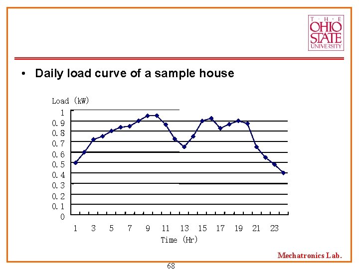
• Daily load curve of a sample house Load (k. W) 1 0. 9 0. 8 0. 7 0. 6 0. 5 0. 4 0. 3 0. 2 0. 1 0 1 3 5 7 9 11 13 15 Time (Hr) 17 19 21 23 Mechatronics Lab. 68
• We propose an energy management system where solar energy will be used to provide the peak load demand of a modern home. • The objective is to show the combined management of solar energy production and load management can reduce the cost of energy use at home and promote cleaner environment. Mechatronics Lab. 69
Load Management Techniques (1) • Importance of Load Management The load management systems is designed to reduce the demand factor by shaving the peak energy use where the production cost is the highest. The load control can create a load cycle where the production cost can be minimized by planning the generation systems with efficient base load units. Mechatronics Lab. 70
Load Management Techniques (2) • Definitions Connected Load: the rating of the installed devices in the user premises in KW Maximum Demand: the maximum energy in KW when some of the connected loads are used at the same time Load Factor: the ratio of maximum demand in KW and the connected load Load Factor = Average Load / Maximum Load Mechatronics Lab. 71
Load Management Techniques (3) • To plan the generation systems, the power companies need to calculate their annual load factor. • This information can also be used to plan an effective load management system. Mechatronics Lab. 72
Load Management Techniques (4) • The time and implementation an effective load management system depends on a number of factors: Time of day metering and tariff Government policies on renewable energy sources Government policies on clean air standard Mechatronics Lab. 73
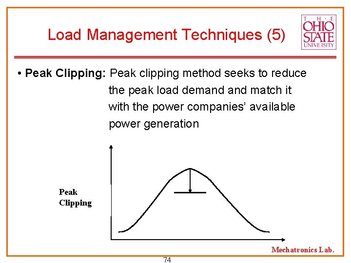
Load Management Techniques (5) • Peak Clipping: Peak clipping method seeks to reduce the peak load demand match it with the power companies’ available power generation Peak Clipping Mechatronics Lab. 74
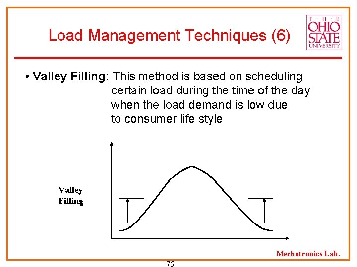
Load Management Techniques (6) • Valley Filling: This method is based on scheduling certain load during the time of the day when the load demand is low due to consumer life style Valley Filling Mechatronics Lab. 75
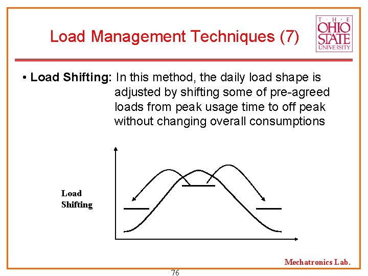
Load Management Techniques (7) • Load Shifting: In this method, the daily load shape is adjusted by shifting some of pre-agreed loads from peak usage time to off peak without changing overall consumptions Load Shifting Mechatronics Lab. 76
Methods of Implementation (1) • Time-of-use-Tariff (TOU): This tariff is based on the price of peak load energy. It is designed to inform the users the real cost of energy consumption. • Objectives: Reduce the rising demands and shape the daily profile Promote the alternative and renewable energy sources Promote distributed energy systems and remove the bottlenecks in transmission Mechatronics Lab. 77
Methods of Implementation (2) • Interruptible Load Control: This method is based on tariffs designed to add spinning reserve to the system in case of system emergency • The tariff rate increases based on the amount of advance time notice given to the customers. • The load reduction is controlled based on demand meter and equipment installed on the customer sites. Mechatronics Lab. 78
Methods of Implementation (3) • Solar Energy for Peak Shaving: The capital cost for installed solar energy system is higher than conventional systems The production of solar energy is essentially cost free No environmental degradation Mechatronics Lab. 79
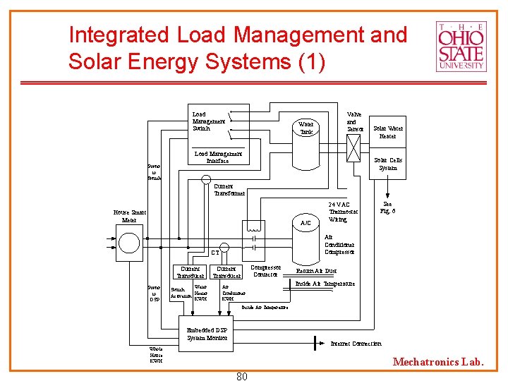
Integrated Load Management and Solar Energy Systems (1) Load Management Switch Power to Switch Valve and Sensor Water Tank Load Management Interface Solar Water Heater Solar Cells System Current Transformer House Smart Meter A/C Power to DSP Water Switch Heater Activation KWH See Fig. 6 Air Conditioner Compressor CT Current Transducer 24 VAC Thermostat Wiring Compressor Contactor Current Transducer Air Conditioner KWH Return Air Dust Inside Air Temperature Embedded DSP System Monitor Internet Connection Whole House KWH Mechatronics Lab. 80
Integrated Load Management and Solar Energy Systems (2) • The control of the load management technology will be based on the development of an embedded DSP based system monitored through Internet connection. • The embedded DSP control systems will control the following: House loads Passive solar energy Active solar energy systems Mechatronics Lab. 81
Integrated Load Management and Solar Energy Systems (3) • House Loads The loads will be classified as essential loads and interruptible loads that can be controlled under a tariff agreement. Examples of interruptible loads are heating and cooling loads. Mechatronics Lab. 82
Integrated Load Management and Solar Energy Systems (4) • Passive Solar Energy Solar water heating has been one of the most successful thermal applications of solar energy use. To have an efficient solar hot water system, it is essential that the system be monitored in real time. The proposed technology of software control will allow that total system be provided as a service by a company whereby remote monitoring and efficiency can be maintained. Mechatronics Lab. 83
Integrated Load Management and Solar Energy Systems (5) • Active Solar Energy This energy is produced by using solar cells to convert the solar energy directly to electric energy as shown in previous figure. The system is monitored and controlled by embedded software control systems for its operation. Mechatronics Lab. 84
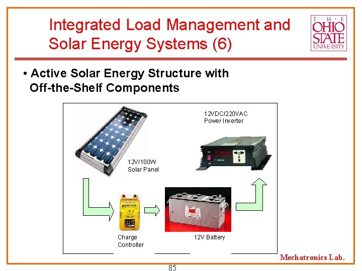
Integrated Load Management and Solar Energy Systems (6) • Active Solar Energy Structure with Off-the-Shelf Components 12 VDC/220 VAC Power Inverter 12 V/100 W Solar Panel Charge Controller 12 V Battery Mechatronics Lab. 85
Integrated Load Management and Solar Energy Systems (7) • Solar Panel - Solar. PRO plug’n’play 100 W solar panels The Solar. PRO plug’n’play™ 100 is produced by ICP Global Technologies. It comes with a charge controller and all wiring/hardware. Built-in LED indicator displays the charging level. 100 Watts rated power at 15 volts operating voltage Mechatronics Lab. 86
Integrated Load Management and Solar Energy Systems (8) • Battery PVX-490 T from Concord Battery Corporation: 12 V, 48 A • Hrs • Trace/Xantrex C 40 Charge Controller From Xantrex Technology, Inc. Mechatronics Lab. 87
Integrated Load Management and Solar Energy Systems (9) • Power Inverter – IPS 1000 DC/AC Pure. Sine Inverter From Analytic Systems, Inc. The IPS Series of ‘True Sine Wave’ Inverters is designed specifically for running computers and other electronics in mobile and other off-grid locations. 120 VAC / 60 Hz fully regulated output 1000 Watts of continuous output power Mechatronics Lab. 88
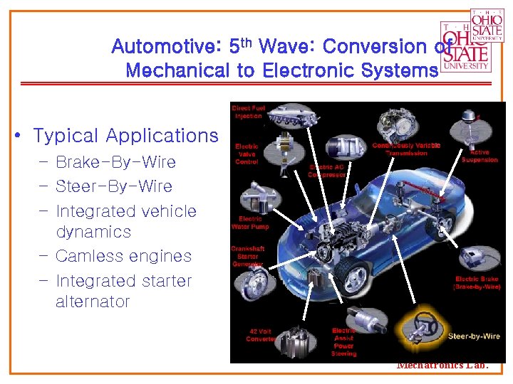
Automotive: 5 th Wave: Conversion of Mechanical to Electronic Systems • Typical Applications – Brake-By-Wire – Steer-By-Wire – Integrated vehicle dynamics – Camless engines – Integrated starter alternator Mechatronics Lab.
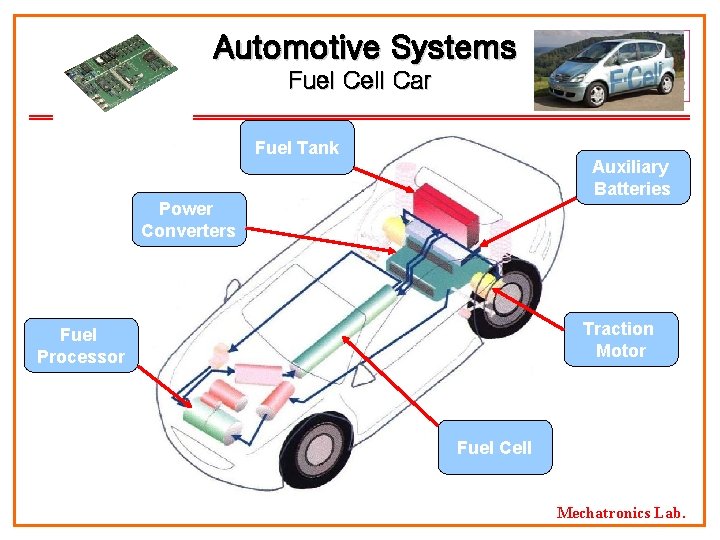
Automotive Systems Fuel Cell Car Fuel Tank Auxiliary Batteries Power Converters Traction Motor Fuel Processor Fuel Cell Mechatronics Lab.
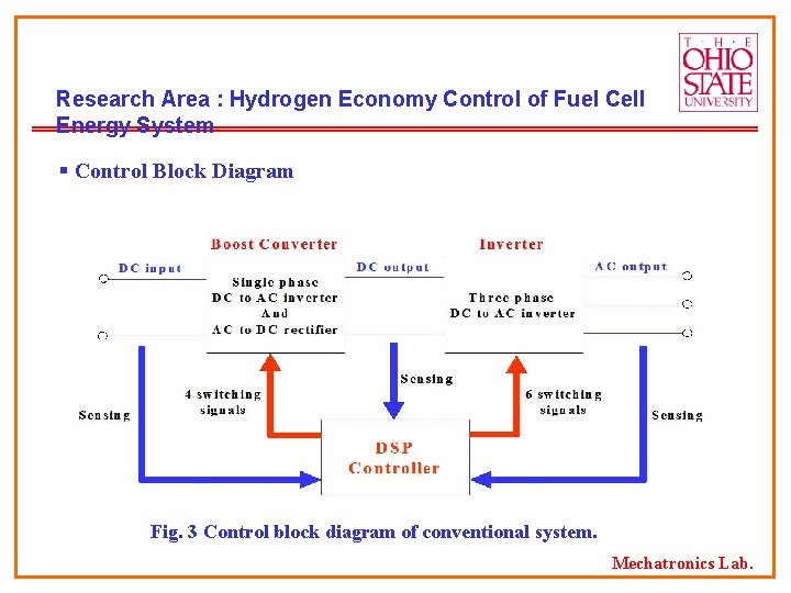
Research Area : Hydrogen Economy Control of Fuel Cell Energy System § Control Block Diagram Fig. 3 Control block diagram of conventional system. Mechatronics Lab.
1. A Power Converter connected in a Stand-alone AC System (3) Research Issues Ø Autonomous power system Voltage, power quality and reliability requirements of the customers Ø Power factor correction Elimination of harmonic current and voltage components Compensation of the reactive power and harmonic load current components P and Q controls independently Ø Stability of frequency and voltage in load pick up or load shading Mechatronics Lab.
Recent IEEE Power Electronics Transaction Papers In Control of Distributed Generation • • • “Control of Distributed Generation Systems, Part I: Voltages and Currents Control, ” Mohammad N. Marwali, Ali Keyhani, IEEE Transactions on Power Electronics, in print. “Control of Distributed Generation Systems Part II: Load Sharing Control, ” Mohammad N. Marwali, Jin. Woo Jung, and Ali Keyhani, IEEE Transactions on Power Electronics, in print. “An Integrated Virtual Learning System for the Development Motor Drive Systems, ” A. Keyhani, M. N. Marwali and Gerald Baumgartner, IEEE Transaction in Power Systems, Paper number TR 12061 (In press) Mechatronics Lab.
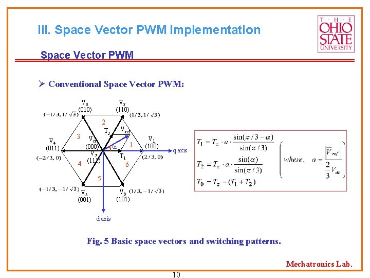
III. Space Vector PWM Implementation Space Vector PWM Ø Conventional Space Vector PWM: V 3 (010) V 2 (110) 2 V 4 (011) 3 4 V 0 (000) V 7 (111) Vref T 2 1 T 1 V 1 (100) q axis 6 5 V 6 (101) V 5 (001) d axis Fig. 5 Basic space vectors and switching patterns. Mechatronics Lab. 10
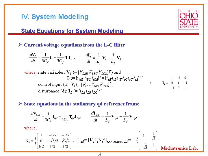
IV. System Modeling State Equations for System Modeling Ø Current/voltage equations from the L-C filter , where, state variables: VL (= [VLAB VLBC VLCA]T ) and Ii (= [ii. AB ii. BC ii. CA]T = [ii. A-ii. B-ii. C-ii. A]T ) control input (u): Vi (= [Vi. AB Vi. BC Vi. CA]T ) disturbance (d): IL (= [i. LA i. LB i. LC]T ) , . Ø State equations in the stationary qd reference frame where, , Tiqd = [Ks. Ti. Ks-1]row, column, 1, 2 = Mechatronics Lab. 14
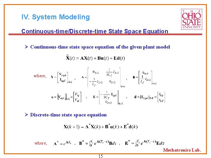
IV. System Modeling Continuous-time/Discrete-time State Space Equation Ø Continuous-time state space equation of the given plant model where, , , Ø Discrete-time state space equation where, , , Mechatronics Lab. 15
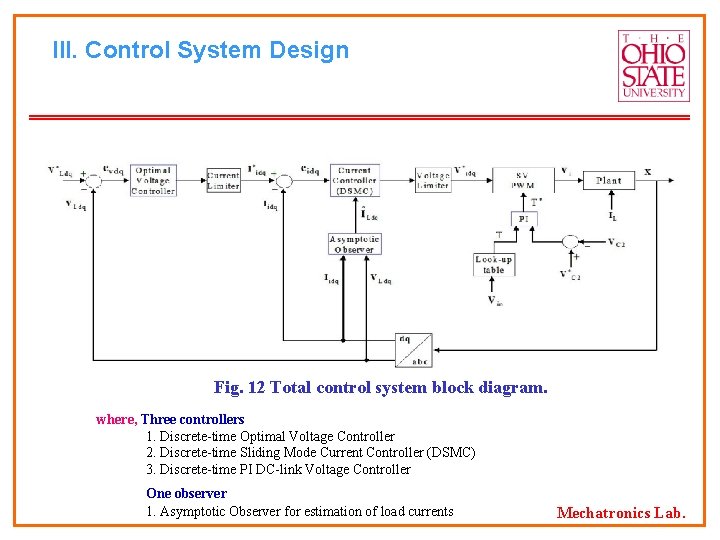
III. Control System Design Fig. 12 Total control system block diagram. where, Three controllers 1. Discrete-time Optimal Voltage Controller 2. Discrete-time Sliding Mode Current Controller (DSMC) 3. Discrete-time PI DC-link Voltage Controller One observer 1. Asymptotic Observer for estimation of load currents Mechatronics Lab.
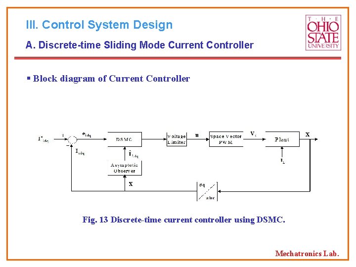
III. Control System Design A. Discrete-time Sliding Mode Current Controller § Block diagram of Current Controller Fig. 13 Discrete-time current controller using DSMC. Mechatronics Lab.
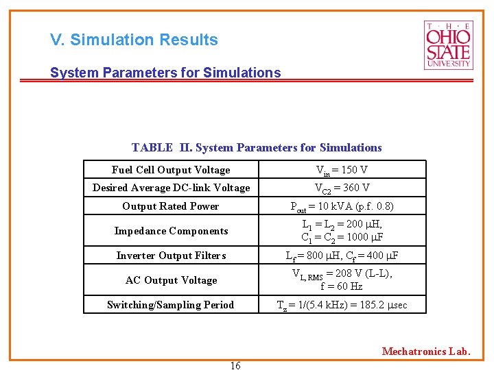
V. Simulation Results System Parameters for Simulations TABLE II. System Parameters for Simulations Fuel Cell Output Voltage Vin = 150 V Desired Average DC-link Voltage VC 2 = 360 V Output Rated Power Pout = 10 k. VA (p. f. 0. 8) Impedance Components L 1 = L 2 = 200 H, C 1 = C 2 = 1000 F Inverter Output Filters Lf = 800 H, Cf = 400 F AC Output Voltage VL, RMS = 208 V (L-L), f = 60 Hz Switching/Sampling Period Tz = 1/(5. 4 k. Hz) = 185. 2 sec Mechatronics Lab. 16
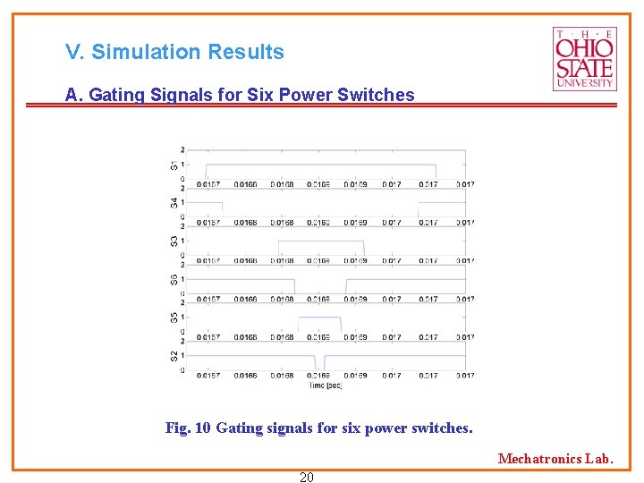
V. Simulation Results A. Gating Signals for Six Power Switches Fig. 10 Gating signals for six power switches. Mechatronics Lab. 20
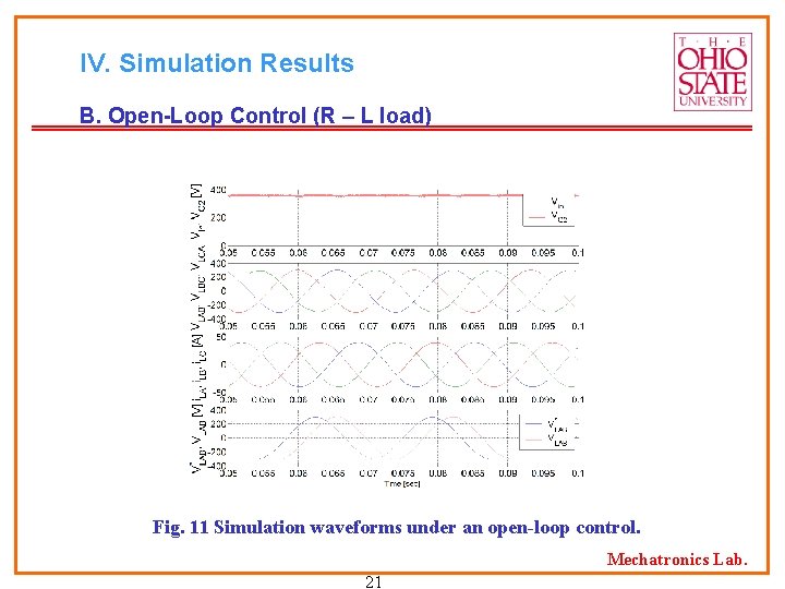
IV. Simulation Results B. Open-Loop Control (R – L load) Fig. 11 Simulation waveforms under an open-loop control. Mechatronics Lab. 21
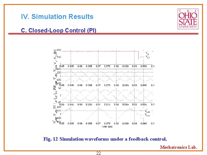
IV. Simulation Results C. Closed-Loop Control (PI) Fig. 12 Simulation waveforms under a feedback control. Mechatronics Lab. 22
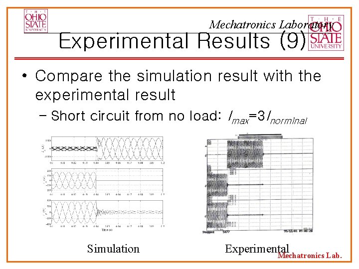
Mechatronics Laboratory Experimental Results (9) • Compare the simulation result with the experimental result – Short circuit from no load: Imax=3 Inorminal Simulation Experimental Mechatronics Lab.
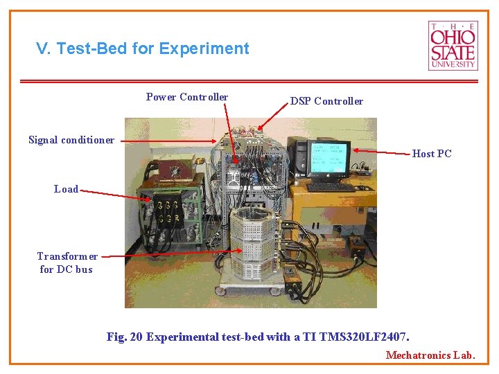
V. Test-Bed for Experiment Power Controller DSP Controller Signal conditioner Host PC Load Transformer for DC bus Fig. 20 Experimental test-bed with a TI TMS 320 LF 2407. Mechatronics Lab.
Government Policies • Rational Policy can be developed based: • Hydrogen Economy Distributed Generation • Transportation • Total Cost of Electric Energy, production, transmission, distribution, and government excessive cost. • A suggested policy: A rate reduction as function of total demand. • Benefits: 1. Cleaner Environment 2. Development of new industries. 3. Job creation. Mechatronics Lab. 89
- Slides: 103