discri clock TDC discri funout ADC div Geiger


/e MPPC Vbreak =-70. 3(V) C= 251 (f.")


- Slides: 28
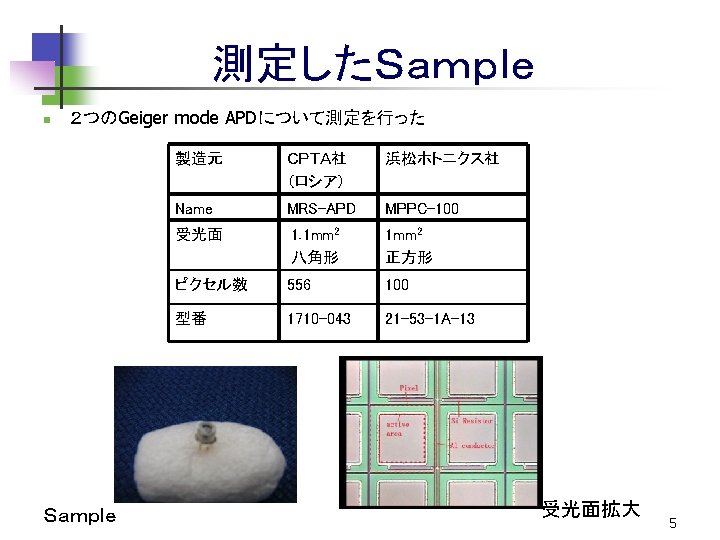
セットアップ discri clock TDC discri funout ADC div レーザー Geiger mode APD AMP NDフィルター Black box n n n Vsource clock ・・・ 1 k. Hz AMP・・・HPK speed amp (C 5594) (36 d. B) laser ・・・ λ=636 nm TDC ・・・ resolution 25 ps ADC ・・・ resolution 0. 25 pc 0. 5peでThreshold Sample レーザー NDフィルター 6
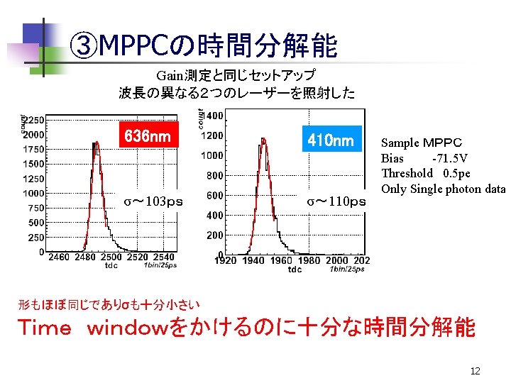
① Gain 測定 Vbias=49. 5 V, 21℃, noise~1. 4 MHz Vbias=71. 5 V, 23℃, noise~1. 0 MHz MPPC MRS-APD 1 peσ=2. 0 pedestal n n Gain S/N 1 peσ=3. 6 2 pe 6. 6× 10⁵ 7. 7 n n Gain 1. 8× 10⁶ S/N 12. 4 Gamp=AMPのGain エネルギー分解能が非常によい Gainも高い 1光子検出可能 7
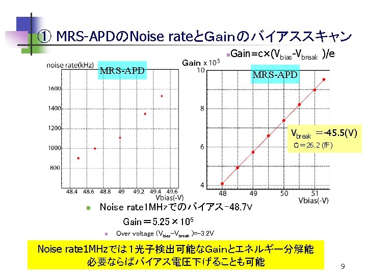
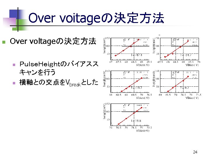
① MPPCのNoise rateとGainのバイアススキャン Gain n Gain=c×(Vbias-Vbreak )/e MPPC Vbreak =-70. 3(V) C= 251 (f. F) n Noise rate 1 MHzのバイアス-71. 5 V Gain= 1. 8× 10⁶ n Over voltage (Vbias-Vbreak )=-1. 2 V 8
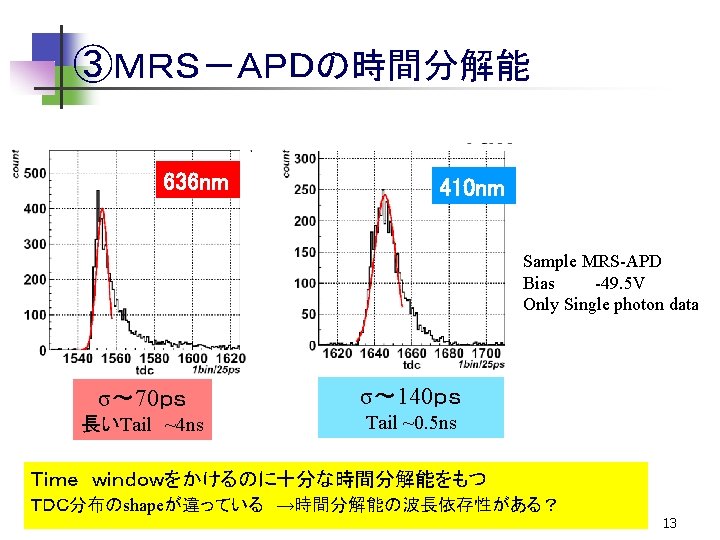
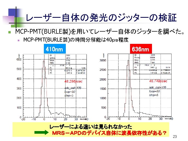
時間分解能の波長依存性の原因 n This is plot of Si. PM, not MRS-APD Geiger regionで電子ホール対を作る reference: ICFA Instrum. Bull. 23: 28 -41, 2001 すぐにGeiger放電が起こる→早いTiming n Drift regionで電子ホール対を作る Geiger regionまでドリフト →遅いTiming l (nm) 吸収長(mm) 410 0. 16 636 3. 65 Red laser σ~ 70 ps Tail ~ 4 ns Geiger region Drift region両方で吸収 Blue laser σ~ 140 ps Tail ~ 0. 5 ns ほぼDrift regionのみで吸収 MRS-APDとMPPCの違い g e- h n+ g p+ e- h →内部構造の違い? pe- h 14
波形 1 pe 10 m. V 1 ns amp x 65 22