Discrete Math Logic Unit Jill Hubbard Tualatin High

Discrete Math – Logic Unit Jill Hubbard Tualatin High School

Oregon Department of Education approved discrete math advanced knowledge and skills • D. 8 Logic: Understand the fundamentals of propositional logic, arguments, and methods of proof. • D. 8. 1 Use truth tables to determine truth values of compounded propositional statements. • D. 8. 3 Determine whether two propositions are logically equivalent. • D. 8. 5 Construct logical arguments using laws of detachment (modus ponens), syllogism, tautology, and contradiction

Materials Needed • Logisim free logic simulator – http: //sourceforge. net/projects/circuit/ • Access to a computer

First some vocabulary we’ll see • • • Proposition Compound Propositions Primitive propositions Logical Operators Truth Table Conjunction (AND) Disjunction (OR) Negation (NOT) What other logical operators do you know? Tautology Contradiction

Propositions • A proposition is a statement that is either true or false – 2+2=4 (true) – New York City is in Oregon (false) – Today is Friday (its either true or false) – Do your homework (not a proposition) – It’s raining outside (probably true in Oregon!)

Compound and Primitive Propositions • Compound Propositions are propositions that are composed of sub-propositions connected together in various ways – roses are red and violets are blue – Mark is smart or he studies a lot • Primitive propositions can not be broken down into simpler propositions – If it’s not a composite proposition, it’s a primitive proposition

What do you think this means? • The truth value of a compound proposition id determined by the truth values of it subpropositions together with the way in which they are connected – John is short OR John is tall • If either part is true, the entire proposition is true – John is short AND John is tall • Both parts have to be true for the entire proposition to be true.
 p –")
Basic Logical Operators Conjunction • Conjunction: p q / (p * q) p – Read as p AND q – A truth table is used to shows q how a logical operator works – Use Logisim to model the AND operator and fill in the truth table – Based on your truth table, write a definition of how the AND operator works p q p*q AND p q F F F T T p q
 p –")
Basic Logical Operators Disjunction • Disjunction: p q / (p + q) p – Read as p OR q – A truth table is used to q shows how a logical operator works – Use Logisim to model the OR operator and fill in the truth table – Based on your truth table, write a definition of how the OR operator works p q p+q OR p q F F F T T p q

Basic Logical Operators Negation • Negation: ¬p / !p – Read as NOT p – Use Logisim to model the NOT operator and fill in the truth table – Based on your truth table, write a definition of how the NOT operator works – Let p be the statement 2+2 = 5 (true or false) – Give an example of a negation of this statement ¬p p !p p F T ¬p
 • Use Logisim to model these operators •")
Other Logical Operations (NAND, NOR, XNOR) • Use Logisim to model these operators • Create a truth table for each operator • Based on your truth table, write a definition of how the operator works • XOR: read as exclusive OR • XNOR: read as exclusive NOR NAND NOR XOR

Relationships between logical operators • People are related to each other right? So are logic gates. But you need to figure them out! – What the relationship between the AND gate and the NAND gate – What the relationship between the OR gate and the NOR gate – What the relationship between the OR gate and the XOR gate. What makes it so exclusive anyway? – What the relationship between the XOR gate and the XNOR gate

Truth Tables for Compound Propositional Statements • Create a truth table for the following compound propositional statement: (p q) (¬ p q) (p * q) + (!p * q) mathematicians nomenclature engineers nomenclature • Use Logisim to model this statement • Run the simulator to make it matches your truth table. If it doesn’t, you made a mistake and must figure out how to fix it! • From here on out, let’s use an engineer’s nomenclature

What the model looks like
 +")
The Mathematicians Method p q !p p*q !p * q (p * q) + (!p * q) F F T T F T T T F F F T T F T
 + (!p * q) – Sum of products")
The Engineers Method (p * q) + (!p * q) – Sum of products form – Each term produces a true expression – So, the expression is true when • p is true AND q is true OR • p is false (!p) AND q is true – Everywhere else, the expression is false – Engineers are lazy!

Tautologies • Tautologies are propositions that are always true no matter what the truth values if their variables are – (p + !p) is a tautology – Why? If p is true, then !p is false and visa versa – The OR logical operator states that if either p or !p is true, the result is true. One of those MUST be true – Use the simulator to build this and test it.

Contradictions • Contradictions are propositions that are always false no matter what the truth values if their variables are – (p * !p) is a tautology – Why? If p is true, then !p is false and visa versa – The AND logical operator states that if either p or !p is false, the result is false. One of those MUST be false – Use the simulator to build this and test it.

Simulate & Fill In the Truth Table p p * !p F T p + !p

Tautologies & Contradictions • Let p stand for the statement “It is cold outside” • Then !p means it is not cold outside • The proposition, p * !p would mean that it is cold outside and it is not cold outside. Clearly, always false and therefore a contradiction • The proposition, p + !p would mean that it is cold outside or it is not cold outside. Clearly, always true and therefore a tautology

Tautologies & Contradictions • Is the following proposition a tautology or a contradiction? p + !(p * q) • Prove using a truth table • Prove using the Logisim simulator

Logical Equivalence • Two propositions are logically equivalent if they have identical truth tables • How is it possible that two propositions can have the same truth table? Take for example the following 2 propositions: !(p * q) !p + !q
 !p + !q p q p*q !(p * q)")
Logical Equivalence !(p * q) !p + !q p q p*q !(p * q) F F T T T p q !p !q !p + !q T F F T T T F T F F T T F T T F F F

Logical Equivalence • When engineers design circuits, the goal is to create designs that work robustly and are cheap • The fewer gates engineers use, the cheaper the design will be • Therefore, it is critical that engineers simplify their design to create cheap but equivalent logic • Engineers use logic synthesizers to help them do the task of logic simplification.

Engineering Applications • Engineers use 1’s and 0’s instead of True and False • 1 means True and 0 means False • All truth tables therefore use 1’s and 0’s • Computers use the binary number system • When engineers create a design, their first job is to determine the interface for their design (the inputs and outputs needed to get the job done).

Number Systems Decimal – base 10 • Remember back a long time ago when you were learning how to count? • Our number system only has 10 symbols (0 -9). So how do we represent the number after 9? • Each number had a place value (Each place value is a power of 10 (base 10) • You multiply each number with its place value and then added them all together. • Now you just take it for granted!

Decimals Numbers - Base 10 10, 000’s 1000’s Place 100’s Place 1’s Place Number 0 0 3 3*1 = 3 0 0 0 2 3 (2*10+3*1)= 23 0 0 1 2 3 (1*100)+(2*10)+(3*1) = 123

Number Systems Binary – Base 2 • Computers use the binary number system or base 2. Base 2 uses only 2 numbers (1 and 0). This makes things very simple. But how do we represent numbers greater then 1? • Just like base 10(decimal), each number had a place value. Each place value is a power of 2 (base 2) • You multiply each number with its place value and then added them all together.

Binary Numbers - Base 2 16’s 8’s Place 4’s Place 2’s 1’s Number Place 0 0 1 1 0 (1*4)+ (1*2) = 6 1 0 1 1 1 (1*16) + (1*4)+ (1*2) Or simply 16+4+2 = 22 16+8+4+2+1 = 31

Counting in Binary is EASY! Binary Number 0 0 0 1 1 1 0 0 1 1 1 Decimal Equivalent zero one two three four five six seven

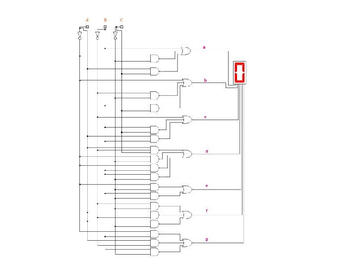
Applications of logic – 7 segment display project in 2 in 1 in 0 YOUR LOGIC out. A out. B out. C out. D out. E out. F out. G Note: A “ 1” on out. A turn on the A segment of the 7 segment display, and a “ 0” on out. A turns segment A off. The same is true for segments B through G

Applications of logic – 7 segment display project • Let’s use what we know to design logic that drives a 7 -segment display. • All inputs and outputs are binary numbers (1’s and 0’s) • If your inputs are all 000, your 7 segment display should display the number 0 • If your inputs are all 111, your 7 segment display should display the number 7 • All input number encodings should work (0 -7)

Let’s Make Truth Tables • Demo the truth table for out. A • Let students figure out equations for out. Bout. G • Review your equations with your instructor

Lets’ Simplify our logic • Show students how to create K-Maps to create equivalent logic with less gates

Let’s use the logic simulator to make and test our design • Students must test their design to make sure they work • If they do not work, they must debug their design
- Slides: 36