
Discontinuous Galerkin Methods for Solving Euler Equations Final








- Slides: 44
Discontinuous Galerkin Methods for Solving Euler Equations Final Presentation May 7, 2013 Andreyev (andreyev@umd. edu) Adviser: James Baeder (baeder@umd. edu)
Motivation Computational Fluid Dynamics (CFD) is widely used in Engineering Design to obtain solutions to complex flow problems when testing is impossible or restrictively expensive. CFD is also used in conjunction with testing to increase confidence in the design process. There are many methodologies for developing CFD codes but can be broken down into 3 categories: 1. Finite Difference Method 2. Finite Volume Method 3. Finite Element Method Each has its advantages and disadvantages. This work is focused on the 3 rd category. A finite element method capable of capturing discontinuities in the solution is developed. It’s appeal is lack of need for a computational stencil, and it’s locality which lends itself to parallelization.
Objectives: Develop a Discontinuous Galerkin Method to solve the Euler Equations in one dimension that allows for up to 3 rd spatial order discretization Develop a Discontinuous Galerkin Method to Solve the Euler Equation in two dimensions that allows for up to 3 rd order spatial discretization Validate both codes against known solutions. Entropy Convection/Shock tube problem for the one dimensional case and an Isentropic Vortex/Double Mach Reflection Problem for the two dimensional case
Outline of Presentation • Euler Equation description • Overview of Current Numerical Methods in CFD -Spatial Discretization Overview -Overview of Conservative Methods -Riemann Problem • Description of General Discontinuous Galerkin Method -Slope Limiting of DG method for stability -Time Stepping using 3 rd order Runge Kutta • 1 D Problem Description -Results/Validation • 2 D Problem Description -2 D Results/Validation • Summary • Review of Schedule • Description of deliverables
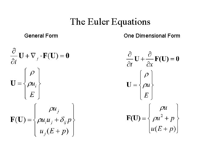
The Euler Equations General Form One Dimensional Form
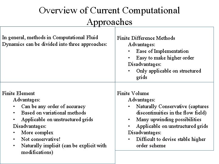
Overview of Current Computational Approaches In general, methods in Computational Fluid Dynamics can be divided into three approaches: Finite Difference Methods Advantages: • Ease of Implementation • Easy to make higher order Disadvantages: • Only applicable on structured grids Finite Element Advantages: • Can be any order of accuracy • Based on variational methods • Applicable on unstructured grids Disadvantages: • More complex • Not conservative! • Naturally implicit (can be explicit with modifications) Finite Volume Advantages: • Naturally Conservative (captures discontinuities in the flow field) • Many upwinding possibilities • Applicable on unstructured grids Disadvantages: • Difficult to devise stable higher order scheme
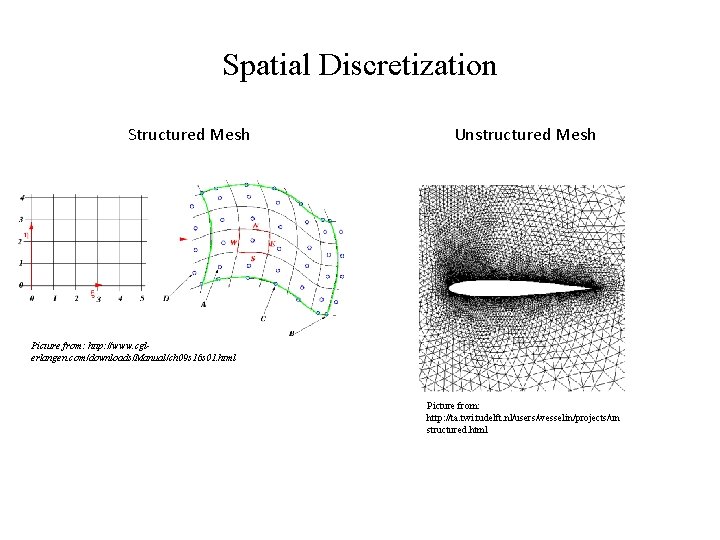
Spatial Discretization Structured Mesh Unstructured Mesh Picture from: http: //www. cglerlangen. com/downloads/Manual/ch 09 s 16 s 01. html Picture from: http: //ta. twi. tudelft. nl/users/wesselin/projects/un structured. html
More on spatial discretization and accuracy “Traditional” numerical methods require a stencil to approximate the spatial derivatives. K=stencil for derivative at tn L=stencil for derivative at tn+1 (only applicable to implicit methods) Picture of stencil Figure From Computational Gasdynamics: Laney 2 1 st and 2 ndorder first derivative approximation
Discretization, Conservation and Flux Capturing Require scheme to capture shocks and other discontinuities “automatically” and not using “shock fitting methods” Higher spatial order shock capturing schemes (>2 nd order) tend to be more oscillatory around the discontinuities because of the larger stencils required thus more points are contributing around areas with large gradients Figure from Computational Gasdynamics: Laney 2
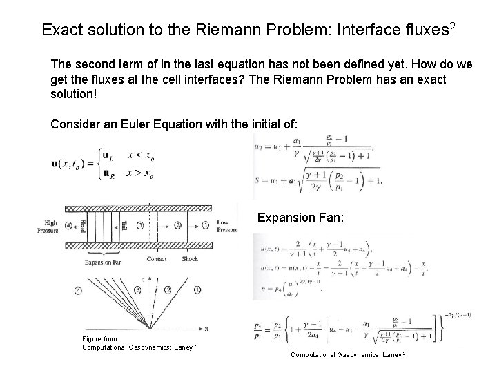
Exact solution to the Riemann Problem: Interface fluxes 2 The second term of in the last equation has not been defined yet. How do we get the fluxes at the cell interfaces? The Riemann Problem has an exact solution! Consider an Euler Equation with the initial of: Expansion Fan: Figure from Computational Gasdynamics: Laney 2
Consider that every cell interface is a Riemann problem! Exact solution to Riemann problem is very expensive and we are not interested in in the solution at all x/t. Look for a suitable approximation for x/t=0 only via Roe Averages All equations taken from Laney (2)
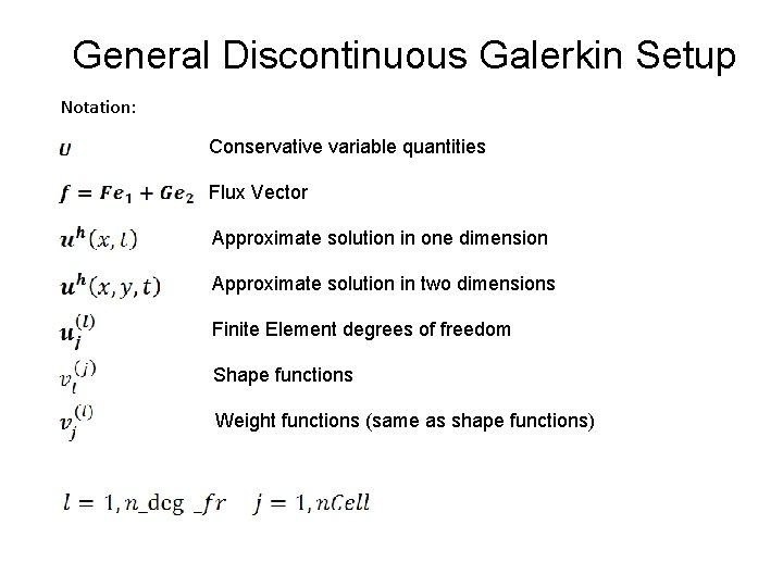
General Discontinuous Galerkin Setup Notation: Conservative variable quantities Flux Vector Approximate solution in one dimension Approximate solution in two dimensions Finite Element degrees of freedom Shape functions Weight functions (same as shape functions)
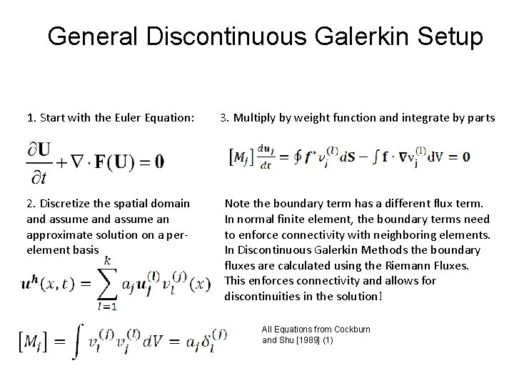
General Discontinuous Galerkin Setup 1. Start with the Euler Equation: 3. Multiply by weight function and integrate by parts 2. Discretize the spatial domain and assume an approximate solution on a perelement basis Note the boundary term has a different flux term. In normal finite element, the boundary terms need to enforce connectivity with neighboring elements. In Discontinuous Galerkin Methods the boundary fluxes are calculated using the Riemann Fluxes. This enforces connectivity and allows for discontinuities in the solution! All Equations from Cockburn and Shu [1989] (1)
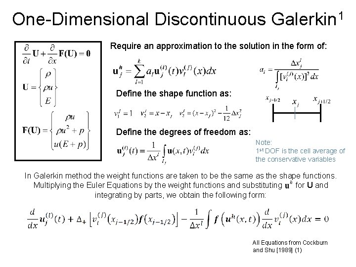
One-Dimensional Discontinuous Galerkin 1 Require an approximation to the solution in the form of: Define the shape function as: Define the degrees of freedom as: Note: 1 st DOF is the cell average of the conservative variables In Galerkin method the weight functions are taken to be the same as the shape functions. Multiplying the Euler Equations by the weight functions and substituting for U and integrating by parts, we obtain the following form: All Equations from Cockburn and Shu [1989] (1)
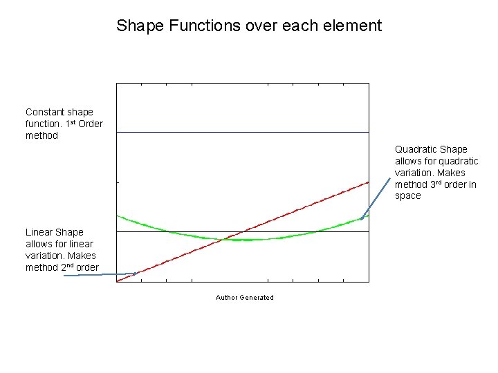
Shape Functions over each element Constant shape function. 1 st Order method Quadratic Shape allows for quadratic variation. Makes method 3 rd order in space Linear Shape allows for linear variation. Makes method 2 nd order Author Generated
Slope Limiting for Stability 1 Around discontinuities DOFs representing the gradients are very large causing oscillations and instabilities. To remedy this problem slope limiters are introduced to insure stability All Equations from Cockburn and Shu [1989] (1)
Runge-Kutta Time Explicit Time Marching • Time integration of the equations will be carried out using a higher order Runge-Kutta technique. • The space discretization in the previous slide converted the PDEs into a system of ODEs in time. • Using Higher Order Runge-Kutta, we carry out the time integration on a perelement basis Note: Time Step is calculated based on the largest Eigenvalue i. e. fastest information transfer All Equations from Cockburn and Shu [1989] (1)
DG Method Approach Require an approximation to the solution in the form of: • Step 1. Calculate the first term in the box (interface flux) using the Roe solver presented earlier • Step 2. Calculate the second term in the box using gauss • Step 3. Define the terms in the box as the residual • Step 4. Use 3 rd Order Runge-Kutta to step in time • Step 5. Apply limiting at each solution update All Equations from Cockburn and Shu [1989] (1)
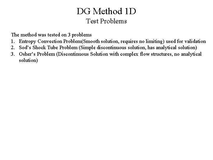
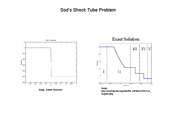
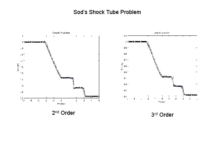
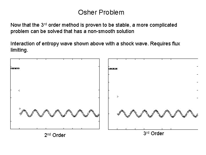
DG Method 1 D Test Problems The method was tested on 3 problems 1. Entropy Convection Problem(Smooth solution, requires no limiting) used for validation 2. Sod’s Shock Tube Problem (Simple discontinuous solution, has analytical solution) 3. Osher’s Problem (Discontinuous Solution with complex flow structures, no analytical solution)
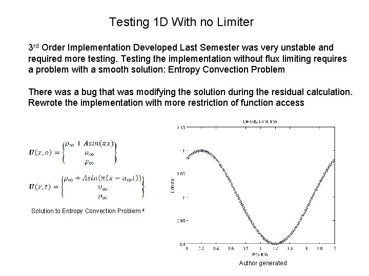
Testing 1 D With no Limiter 3 rd Order Implementation Developed Last Semester was very unstable and required more testing. Testing the implementation without flux limiting requires a problem with a smooth solution: Entropy Convection Problem There was a bug that was modifying the solution during the residual calculation. Rewrote the implementation with more restriction of function access Solution to Entropy Convection Problem 4 Author generated
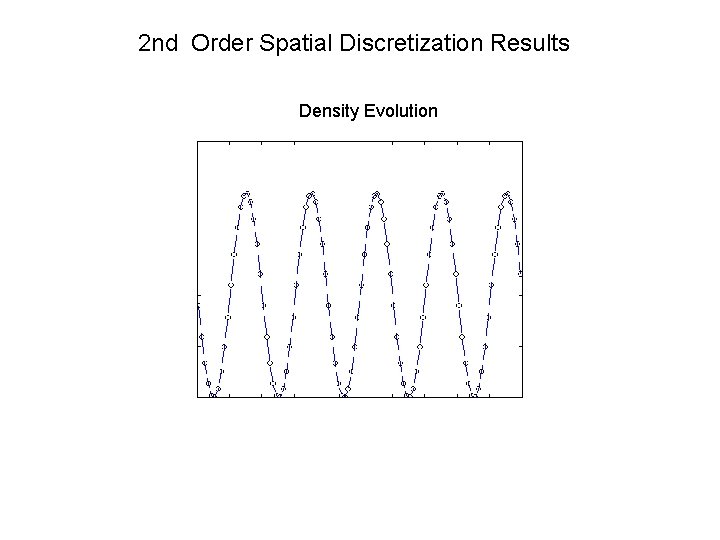
2 nd Order Spatial Discretization Results Density Evolution
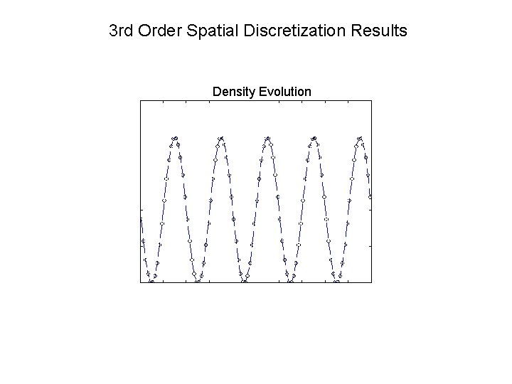
3 rd Order Spatial Discretization Results Density Evolution
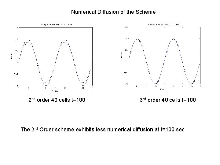
Numerical Diffusion of the Scheme 2 nd order 40 cells t=100 3 rd order 40 cells t=100 The 3 rd Order scheme exhibits less numerical diffusion at t=100 sec
Validation using grid convergence criteria Error vs. dx 3. 50 E+00 3. 00 E+00 2. 50 E+00 2. 00 E+00 -log(error) 1. 50 E+00 2 nd Order 1. 00 E+00 3 rd Order 5. 00 E-01 The solution is run to 100 seconds to allow numerical diffusion to take effect. The norm of the error is calculated 0. 00 E+00 0 0. 5 -log(dx) 1 1. 5 The 3 rd Order scheme is less diffusive, however the error goes down at the same rate as 2 nd order scheme. This could be caused by the fact that time integration is also third order and 100 seconds is a considerable time length of integration
Sod’s Shock Tube Problem Exact Solution Image: Author Generated Image: http: //en. wikipedia. org/wiki/File: Sod. Shock. Tube. Test_ Regions. png
Sod’s Shock Tube Problem 2 nd Order 3 rd Order
Osher Problem Now that the 3 rd order method is proven to be stable, a more complicated problem can be solved that has a non-smooth solution Interaction of entropy wave shown above with a shock wave. Requires flux limiting. 2 nd Order 3 rd Order
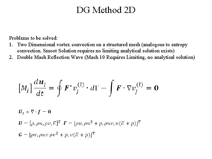
DG Method 2 D Problems to be solved: 1. Two Dimensional vortex convection on a structured mesh (analogous to entropy convection. Smoot Solution requires no limiting analytical solution exists) 2. Double Mach Reflection Wave (Mach 10 Requires Limiting, no analytical solution)
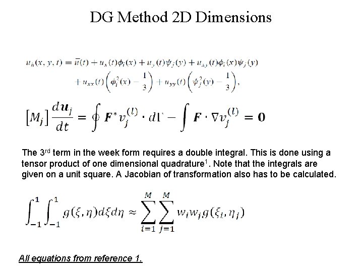
DG Method 2 D Dimensions The 3 rd term in the week form requires a double integral. This is done using a tensor product of one dimensional quadrature 1. Note that the integrals are given on a unit square. A Jacobian of transformation also has to be calculated. All equations from reference 1.
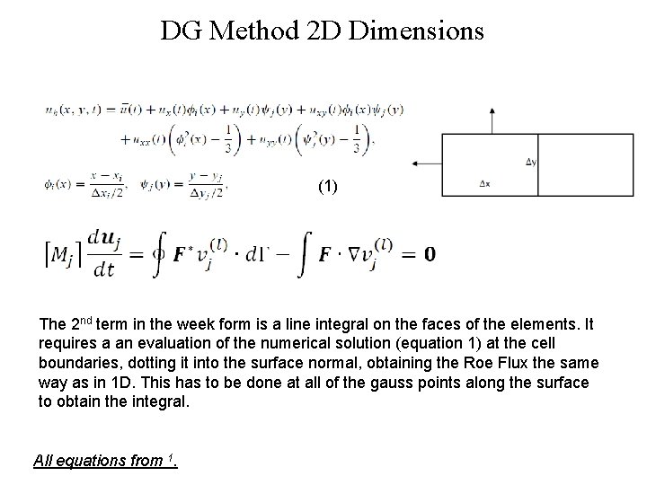
DG Method 2 D Dimensions (1) The 2 nd term in the week form is a line integral on the faces of the elements. It requires a an evaluation of the numerical solution (equation 1) at the cell boundaries, dotting it into the surface normal, obtaining the Roe Flux the same way as in 1 D. This has to be done at all of the gauss points along the surface to obtain the integral. All equations from 1.
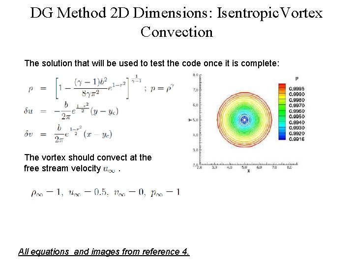
DG Method 2 D Dimensions: Isentropic. Vortex Convection The solution that will be used to test the code once it is complete: The vortex should convect at the free stream velocity. All equations and images from reference 4.
Isentropic Vortex Solution
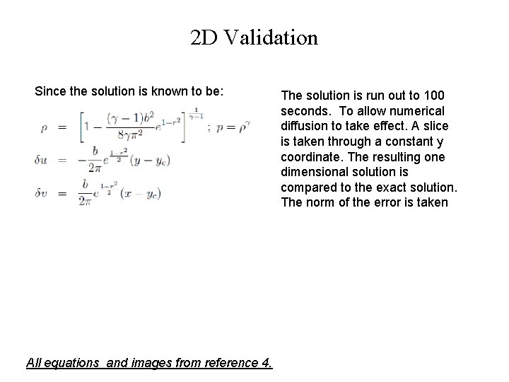
2 D Validation Since the solution is known to be: All equations and images from reference 4. The solution is run out to 100 seconds. To allow numerical diffusion to take effect. A slice is taken through a constant y coordinate. The resulting one dimensional solution is compared to the exact solution. The norm of the error is taken
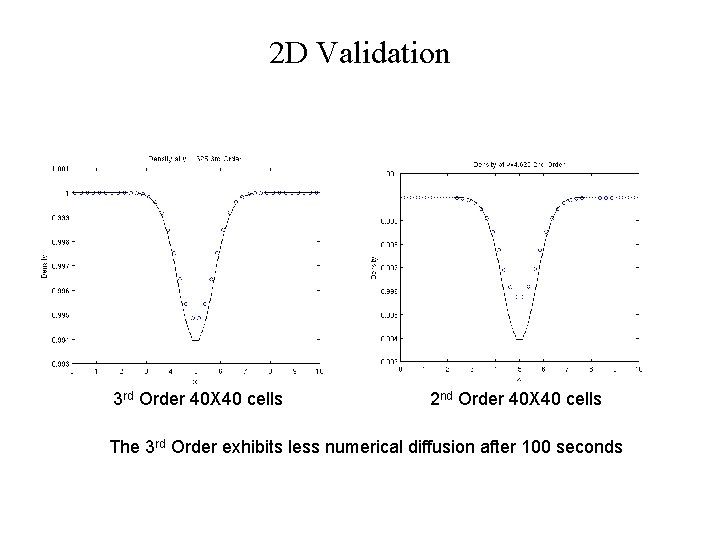
2 D Validation 3 rd Order 40 X 40 cells 2 nd Order 40 X 40 cells The 3 rd Order exhibits less numerical diffusion after 100 seconds
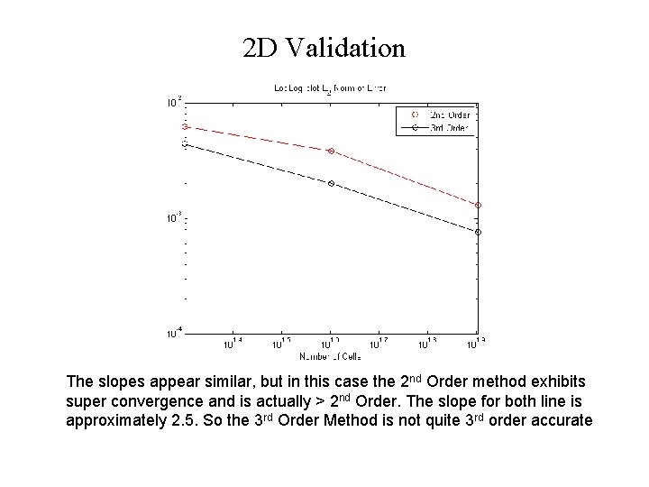
2 D Validation The slopes appear similar, but in this case the 2 nd Order method exhibits super convergence and is actually > 2 nd Order. The slope for both line is approximately 2. 5. So the 3 rd Order Method is not quite 3 rd order accurate
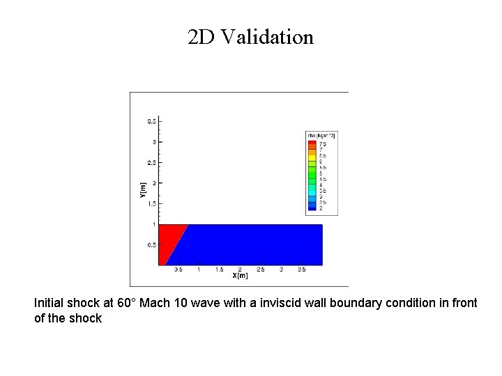
2 D Validation Initial shock at 60° Mach 10 wave with a inviscid wall boundary condition in front of the shock
Exact Solution Does Not Exist For The Double Mach Reflection Problem Visual Comparison Between Papers Is Required
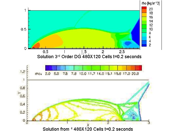
Solution 3 rd Order DG 480 X 120 Cells t=0. 2 seconds Solution from 4 480 X 120 Cells t=0. 2 seconds
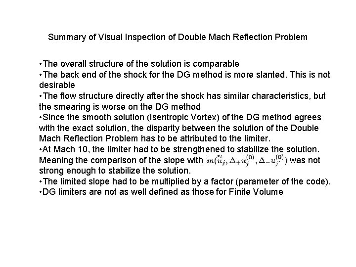
Summary of Visual Inspection of Double Mach Reflection Problem • The overall structure of the solution is comparable • The back end of the shock for the DG method is more slanted. This is not desirable • The flow structure directly after the shock has similar characteristics, but the smearing is worse on the DG method • Since the smooth solution (Isentropic Vortex) of the DG method agrees with the exact solution, the disparity between the solution of the Double Mach Reflection Problem has to be attributed to the limiter. • At Mach 10, the limiter had to be strengthened to stabilize the solution. Meaning the comparison of the slope with was not strong enough to stabilize the solution. • The limited slope had to be multiplied by a factor (parameter of the code). • DG limiters are not as well defined as those for Finite Volume
Summary of Project 1 -D • The one dimensional version of DG method was developed and tested using a smooth solution (entropy convection) and two discontinuous solutions (Sod’s Shock Tube and Osher’s problem) • Results were compared to exact solution of entropy convection at t=100 seconds • 3 rd Order Proved to be less diffusive, but not formally 3 rd order in space. Requires more investigation, possible a different definition of error due to time-based error. • Limiter captures the shock, but diffuses the solution 2 -D • The two dimensional problem of DG was developed and tested using a smooth solution (Isentropic Vortex) and a discontinuous solution (Double Mach Reflection Wave) • Error estimates pending • The limiter allowed for discontinuous solution, but had to be strengthened due to the very large gradients. The solution was comparable to previous works, but did smear the solution near the shock
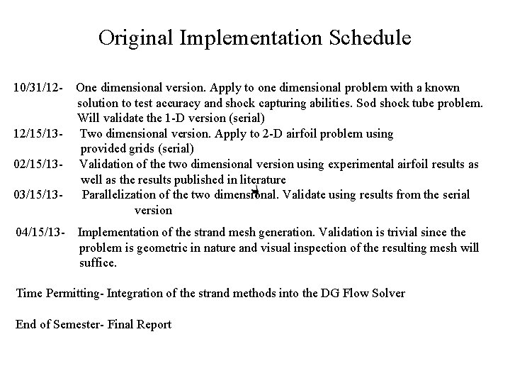
Original Implementation Schedule 10/31/1212/15/1303/15/1304/15/13 - One dimensional version. Apply to one dimensional problem with a known solution to test accuracy and shock capturing abilities. Sod shock tube problem. Will validate the 1 -D version (serial) Two dimensional version. Apply to 2 -D airfoil problem using provided grids (serial) Validation of the two dimensional version using experimental airfoil results as well as the results published in literature Parallelization of the two dimensional. Validate using results from the serial version Implementation of the strand mesh generation. Validation is trivial since the problem is geometric in nature and visual inspection of the resulting mesh will suffice. Time Permitting- Integration of the strand methods into the DG Flow Solver End of Semester- Final Report
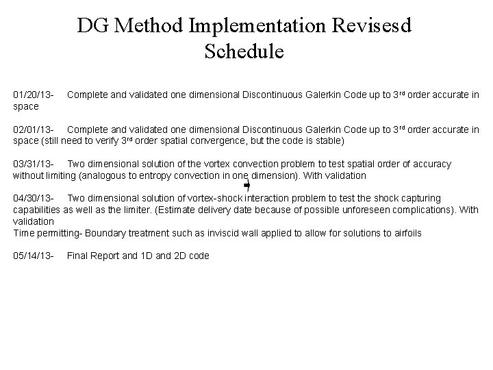
DG Method Implementation Revisesd Schedule 01/20/13 space Complete and validated one dimensional Discontinuous Galerkin Code up to 3 rd order accurate in 02/01/13 - Complete and validated one dimensional Discontinuous Galerkin Code up to 3 rd order accurate in space (still need to verify 3 rd order spatial convergence, but the code is stable) 03/31/13 - Two dimensional solution of the vortex convection problem to test spatial order of accuracy without limiting (analogous to entropy convection in one dimension). With validation 04/30/13 - Two dimensional solution of vortex-shock interaction problem to test the shock capturing capabilities as well as the limiter. (Estimate delivery date because of possible unforeseen complications). With validation Time permitting- Boundary treatment such as inviscid wall applied to allow for solutions to airfoils 05/14/13 - Final Report and 1 D and 2 D code
Questions? ? ?
References: 1. Bernardo Cockburn, Chi-Wang Shu, The Runge-Kutta Discontinuous Galerkin Method for Cnservation Laws V, Multidimensional Systems, Journal of Computational Physics 141 199 -224 (1997) 2. Bernardo Cockburn, Chi-Wang Shu, TVB Runge-Kutta Local Projection Discontinuous Galerkin Method for Conservation Laws II: General Frame Work Mathematics of Computation Volume 52 186 (1989) 3. Culbert B. Laney. Computational Gasdynamics. Cambridge University Press. 1998 4. D. Gosh, Compact-Reconstruction Weighted Essentially Non-Oscillatory Schemes for Hyperbolic Conservation Laws. Doctor of Philosophy Thesis, University of Maryland, College Park 2012.