DISCONTINUITIES Rock vs Rock Mass Discontinuity plane of


 Very low")


, is defined as number of joint per metre length.")


 • Another commonly used roughness classification is proposed by Barton,")
 • In a natural joint, it is very seldom that")
")


,")


- Slides: 32
DISCONTINUITIES Rock vs Rock Mass
Discontinuity = plane of weakness across which the rock is structually discontinuous, possess little or no tensile strength Fissure, faults, joints, bedding plane, cleave, schistosity
Rock Mass Strength • Strength depends on the density, nature and extent of the fractures within it
Rock fractures and their characterization • • orientation spacing length roughness aperture filling block size
Geometrical Characteristics • Joint Sets • Persistence is the areal extent or size of a discontinuity, and can be crudely quantified by observing the trace lengths of discontinuities on exposed surfaces.
Classification of discontinuity persistence Description • • • Surface Trace Length (m) Very low persistence Low persistence Medium persistence High persistence Very high persistence <1 1– 3 3 – 10 10 – 20 > 20
Joint Orientation: Joint Plane Orientation and Representation • In rock mechanics, dip direction/dip format is generally used, e. g. , 210/35, or 030/35, where dip directions always have 3 digitals. • When strike is used, it should be presented as strike/dip 120/35 SW
Joint Spacing Description • Extremely close spacing • Very close spacing • Close spacing • Moderate spacing • Wide spacing • Very wide spacing • Extremely wide spacing Joint Spacing (m) < 0. 02 – 0. 06 – 0. 2 – 0. 6 – 2 2– 6 >6
Joint Frequency Joint frequency (λ), is defined as number of joint per metre length. It is therefore simply the inverse of joint spacing (sj), i. e. , λ = 1 / sj
Block Size Designation • • • Volumetric Joint Count, joints/m 3 Very large blocks Large blocks Medium-sized blocks Small blocks Very small blocks Crushed rock <1 1– 3 3 – 10 10 – 30 > 60
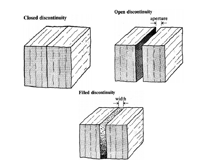
Joint Surface and Opening: Roughness, Matching, Aperture and Filling • A joint is an interface of two contacting surfaces. • The surfaces can be smooth or rough; • They can be in good contact and matched, or they can be poorly contacted and mismatched. • The condition of contact also governs the aperture of the interface. • The interface can also be filled with intrusive or weathered materials/ open
Joint surface roughness • Joint surface roughness is a measure of the inherent surface unevenness and waviness of the discontinuity relative to its mean plane. • The roughness is characterised by large scale waviness and small scale unevenness of a discontinuity. • It is the principal governing factor the direction of shear displacement and shear strength, and in turn, the stability of potentially sliding blocks. • Roughness can be distinguished between small scale surface irregularity or unevenness and large scale undulation or waviness of the discontinuity surface
Definition of joint roughness at different scale Classification of discontinuity. It describes the roughness first in metre scale (step, undulating, and planar) and then in centimetre scale (rough, smooth, and slickensided). The classification is useful to describe the joint surface but does not give any quantitative measure.
Joint Roughness Coefficient (JRC) • Another commonly used roughness classification is proposed by Barton, termed as Joint Roughness Co-efficient • JRC number is 0 for the smooth flat surface and 20 for the very rough surface. • roughness is affected by geometrical scale. In the JRC classification, the value of JRC decreases with increasing size.
Joint Matching Coefficient (JMC) • In a natural joint, it is very seldom that the two surfaces are in complete contact. • There usually exists a gap or an opening between the two surfaces. • The perpendicular distance separating the adjacent rock walls is termed as aperture. • Joint opening is either filled with air and water (open joint) or with infill materials (filled joint) • Open or filled joints with large apertures have low shear strength.
Joint Matching Co-efficient (JMC)
Classification of discontinuity aperture Aperture < 0. 1 mm 0. 1 - 0. 25 mm 0. 25 - 0. 5 mm 0. 5 - 2. 5 mm 2. 5 - 10 mm 1 - 10 cm 10 - 100 cm >1 m Description Very tight Tight Partly open Open Widely open Very widely open Extremely widely open Cavernous
Descriptive terms for joint surface alteration Term Fresh : Description No visible sign of weathering of rock material at joint wall. Discoloured : Colour of the original fresh rock material is changed. The degree of change from the original colour should be indicated. If the colour change is confined to particular minerals this should be mentioned. Decomposed: Rock is weathered to the condition of a soil in which the original materials fabric is still intact, but some or all of the mineral grains are decomposed. Disintegrated: Rock is weathered to the condition of a soil in which the original materials fabric is still intact. The rock is friable, but the mineral grains are not decomposed.
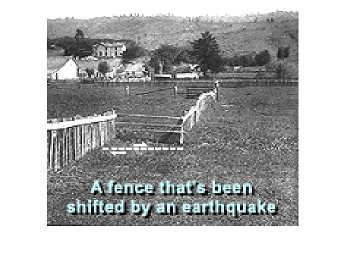
Active Fault • An active fault is a fault which has had displacement or seismic activity during the geologically recent period (Holocene Epoch)(during the last 11, 000 or so years before present). Ex San Andres fault • Master fault : between major tectonic plates, ~100 km, 8 mag earthquake, displacement ~10 m • Major fault : ~10 km, 6. 5 to 7 mag, • Local Fault: <10 km, 6 to 6. 5 mag Refer to your B. Sc. notes
Quaternary dating technique • TL dating • OSL dating • GPS
Features of Active faults How Do Geologists Find Quaternary-Active Faults? • • • Stream Ponding He, Rn emissions Sharp bend along river course Displacement of Quaternary formations LIDAR
Linear valley Sap Pond Offset of drainage
The newest tool to find active faults is Laser Imaging Detection And Ranging (LIDAR), which uses laser light projected from an airplane to make a detailed image of the ground surface, even through trees in a forest.
San Andres Fault
Passive/dead/inactive Fault • Movement has not occurred in man’s history • Mature topography • No seismic potential at present geodynamic condition, may reactivate with changing tectonic conditions • Ex Vakra thrust, Upper Siwalik Boulder Conglo not affected by this fault • Vakra dam situated on Vakra thrust
Fault identification and characterization • Collect all relevant data from remote sensing, and any other sources • Prepare fracture/lineament map • Integrate with other information • Characterization – Known fault (established) – Capable (active) fault = seismic potential – Probable (inferred) fault – Dead (dormant) fault = zero seismic potential
Fault and Earth Movements Earthquake Landslides Liquefaction SCR Earthquake (very short 100 s years to 1000 s of years recurrence interval, shallow focus) • Induced (reservoir) Seismicity • •
Soil Liquefaction • Occurs in a buried layer of unconsolidated, water saturated, generally small to med sand size sed during prolonged shaking in an earthquake • The sed particles reorient themselves to occupy less space and force water out of the pore spaces. • Overlying layers that are unsaturated or more consolidated or frozen find themselves rafted on a layer of liquefied soil that has little or no shear strength and become destabilized making fractures to allow the water to escape in soil boils.
Liquefaction • When wet soil is shaken by earthquake, the soil particles may be jarred apart, allowing water to seep in between them. • This greatly reduces the friction b/w soil particles that gives the soil its strength, and causes the ground to become somewhat like quicksand • When liquefaction happens, buildings just topples as the soil has no strength to support them