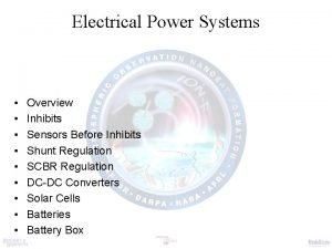
DINO EPS Vendor Presentation 9162020 DINO Electrical Power


- Slides: 29

DINO – EPS Vendor Presentation 9/16/2020 DINO Electrical Power Subsystem Vendor Presentation Mike Wong Jasenko Alagic Kevin Mc. Williams December 08, 2003

DINO – EPS Vendor Presentation 9/16/2020 Top Level Integration Electrical Power System Panel Side Panel Brackets EPS Control Card Flexible Integrated Thin -film Solar array Body Mount Solar Array Colorado Space Grant Consortium 2

DINO – EPS Vendor Presentation 9/16/2020 Spacecraft Level Requirements • • Placed on-orbit from Internal Cargo Unit aboard Space Shuttle LEO, International Space Station orbit (51. 6º, ~400 km altitude) Mission duration between 6 and 12 months 55 minute sun-side, 35 minute eclipse 10 W power during safe mode 90 W power usage during Normal-daytime operations 15 W power usage during Night time operations Colorado Space Grant Consortium 3

DINO – EPS Vendor Presentation 9/16/2020 Power Subsystem Requirements • • • The system will weigh < 2. 25 kg The system will communicate with C&DH through a shared RS-232 line The system will provide +/- 12 V line to ADCS The system will provide a 28 V line to structures for deployment mechanisms The system will provide C&DH and COMM receiver continuous power The secondary battery assembly will last for 6, 000 day/night cycles The system will provide 90 W nominal power during the day, 15 W at night EPS will provide 5 V rated to 30 W, +/-12 V rated to 30 W and 28 V lines with power rating TBD The system will receive instructions from C&DH The system will provide data to C&DH for processing The system will operate at temperatures between 0 and 40 degrees Celsius with a nominal operating temperature of 20 degrees Celsius Colorado Space Grant Consortium 4

DINO – EPS Vendor Presentation 9/16/2020 Key Requirements • • • The satellite shall be unpowered while in the shuttle payload bay Power inhibits are required to provide 3 fault tolerance to inadvertent operation All inhibits shall verify their current status prior to launch Current will be monitored on primary inputs and outputs of the EPS board Each battery shall have 4 independent inhibits; one on the negative lead and three on the positive lead A fuse shall be located in line with the ground leg of each battery • Voltages shall be monitored on the busses, battery, and solar arrays • Solar arrays shall be isolated using 1 independent inhibit • The spacecraft loads shall be isolated using 1 independent inhibit • The EPS shall interface with the Ground Support Equipment (GSE) to perform test operations Colorado Space Grant Consortium 5

DINO – EPS Vendor Presentation 9/16/2020 Safety Requirements - Battery • Battery; JSC 20793 – Manned Space Vehicle Battery Safety Handbook • Lithium battery systems must be three-fault tolerant – requires 4 independent inhibits • Stack packaging shall protect against corrosion and shorts due to electrolyte leakage • Cell vents shall be oriented upwards during launch on the shuttle • Cells must be provided with individual temperature monitoring capability • Charging/discharging must be done in such a way as to not damage the cells • The cells shall be maintained above 3. 2 V cell voltage to prevent over discharge • The stack shall be nominally charged to 95% of capacity to prevent overcharge of individual cells • Battery assembly must be maintained between 0 and 40 degrees Celsius Colorado Space Grant Consortium 6

DINO – EPS Vendor Presentation 9/16/2020 Safety Requirements - Other • Wiring • All wires/fuses must be de-rated for worst-case conditions • Wire harness must not interfere with or be damaged by structure • Wire bundles must not overheat • All inhibits must be able to have status verified from GSE without spacecraft power Colorado Space Grant Consortium 7

DINO – EPS Vendor Presentation 9/16/2020 Electrical Power System Block Diagram SCIENCE Cam 1 COMM HOP SW Radio 2 Cam 2 Radio 1 Imaging GSE 15 V Prim SA Back SA Wireless TNC TR 1 RS-232 I/O S Control Card 5 V TR 3 EMC 1 EP 5 V TR 2 Mag. STRUCTURES HOP C&DH ADCS Sun Sen. Battery EMC 2 28 V 12 V EMC 3 EMC 4 Boom Colorado Space Grant Consortium 8

DINO – EPS Vendor Presentation 9/16/2020 Inhibits Layout Diagram • Main EPS uses separation switches from ICU to trigger system start-up • Connect to two FET on the high leg of the battery, one on the ground leg • Method to get power into EPS is via a dedicated SA string • Solar Array (SA) string switches will act as SA inhibits • ICU for startup string • Subsystem load switches will act as spacecraft load inhibits Colorado Space Grant Consortium 9

DINO – EPS Vendor Presentation 9/16/2020 Electrical Power System Description • Direct energy transfer system • Single Solar-Array technologies • • Conventional body-mount crystalline cells Thin-Film (FITS) Flexible Array • System will switch solar array strings and spacecraft loads, and will require 4 switches for the FITS • • • Will require 16 (TBR) switches for the backup SA 4 power distribution switches capable of transferring less than 3 Amps 12 power distribution switches capable of transferring less than 1 Amp • • • System will use 4 A-hr Lithium Polymer cells at 3. 7 Volts for power storage 4 Cells will be in series, for a 15 V +/- 2 V, 4 Ahr battery assembly Battery charging will be accomplished using several charging modes: • Nominal sub-capacity charging; entire stack is charged to 95% capacity • This will be the default mode • • • Full-charge; entire stack charged to 100% capacity Cell conditioning over-charge; as stack ages, it will lose capacity, which can be restored by judicious over-charging Temperature and voltage monitoring will be the primary means of controlling battery Colorado Space Grant Consortium 10

DINO – EPS Vendor Presentation 9/16/2020 Electrical Power System Mission Modes • • Start-up Mode • • • ADCS, C&DH, COMM on Activate High-Output Paraffin actuator (HOPS) Deploy boom • tip-mass experiment views other deployments • • • All systems un-powered Inhibits must trigger start-up event EPS activates, followed by C&DH, and COMM Charge battery immediately Deployment Mode Deploy FITS solar array, primary power source Deploy aero fins by activating Electric Memory Composite (EMC) hinges Normal Mode 90 W power, two sub-modes • Transmit Mode, cameras off, COMM in transmit (TX) and receive (RX) • Science Mode, cameras on, COMM in RX • Maximum sun time of 55 minutes • Night Mode • • C&DH, COMM on 15 W nominal power provided to the spacecraft from the battery Maximum eclipse time of 35 minutes Safe Mode • All non-essential systems off, C&DH, COMM in RX and EPS on Colorado Space Grant Consortium 11

DINO – EPS Vendor Presentation 9/16/2020 Electrical Power System Control Card Block Diagram C&DH (RS-232) Cmd/Monitor line Power line 5 V Reg. FITS SA Interface Body Mount Charge Control & Monitoring +/- 12 V Reg 28 V Battery Subsystem Interface PMAD Battery Colorado Space Grant Consortium EPS Control Card • Provides SA switch interface • Provide charge control/Monitor • Provides C&DH RS 232 interface • Provides secondary Power • 5 V • +/-12 V • 28 V • Provides 19 load switches to the spacecraft 12

DINO – EPS Vendor Presentation 9/16/2020 Switch List Function Number of Switches Amps Volts ADCS 3 0. 500 5 COMM RX 2 1. 500 12 Cameras 2 0. 200 5 TNC 1 0. 500 12 Frangibolts 3 0. 850 28 Memory Hinges 4 0. 357 28 Antenna 1 (TBD) COMM TX 1 0. 100 5 Colorado Space Grant Consortium 13

DINO – EPS Vendor Presentation 9/16/2020 Battery Schematic Credit: Valence Electronics www. valence. com Battery Lithium Ion-Polymer cells Prismatic design 4 A-hr capacity 4 cells in series 4 flight temp monitors 4 GSE temp monitors Cell voltage to GSE Battery voltage to flight Colorado Space Grant Consortium 14 BATC PROPRIETARY

DINO – EPS Vendor Presentation 9/16/2020 Flat Conductor Layer 1 Colorado Space Grant Consortium 15 BATC PROPRIETARY

DINO – EPS Vendor Presentation 9/16/2020 Flat Conductor Layer 2 Colorado Space Grant Consortium 16 BATC PROPRIETARY

DINO – EPS Vendor Presentation 9/16/2020 FLAT CONDUCTOR CABLE SURFACE MOUNT CONNECTOR INTERFACE RIGID SECTION TEMP SENSOR INTERFACE PADS, TYP. KEY FEATURES • RIGID – FLEX CONSTRUCTION • 2 CONDUCTOR LAYERS • RIGID SECTION FOR SECURE CONNECTOR INTERFACE AND RELIABLE ROUTING OF VIAS FROM THE FLEXIBLE, CONDUCTOR LAYERS TO CONNECTOR INTERFACE FLEXIBLE CONDUCTOR SECTION BATTERY INTERFACE PADS, TYP. Colorado Space Grant Consortium 17 BATC PROPRIETARY

DINO – EPS Vendor Presentation 9/16/2020 BATTERY ASSEMBLY KEY FEATURES • FOUR (4) 4. 0 AMP-HOUR LITHIUM ION CELLS • TWO (2) TEMPERATURE SENSORS PER CELL • BATTERIES AND TEMPERATURE SENSORS SHALL BE SOLDERED AND STAKED TO THE FLAT CONDUCTOR CABLE BATTERY CELL, TYP. TEMP. SENSOR, TYP. Colorado Space Grant Consortium 18 BATC PROPRIETARY

DINO – EPS Vendor Presentation 9/16/2020 POWER PANEL ASSEMBLY KEY FEATURES • COMPOSITE PANEL, BATTERY INSULATOR, BATTERY ASSMELBY AND BATTERY RADIATOR ARE COMPRESSION MOLDED TOGETHER TO CREATE AN ITEGRATED, STRUCTURAL POWER PANEL. • EPS BOARD WILL PROVIDE POWER DISTRIBUTION TO DESIGNATED SPACECRAFT INSTRUMENTS SIDE PANEL BRACKETS (CU – CSGC) EPS ELECTONICS BOARD (BROAD REACH ENGINEERING) COMPOSITE PANEL (SPACEWORKS, INC. ) BATTERY INSULATOR (SPACEWORKS, INC. ) BATTERY ASSEMBLY (BATC) BATTERY RADIATOR (SPACEWORKS, INC. ) Colorado Space Grant Consortium 19 BATC PROPRIETARY

DINO – EPS Vendor Presentation 9/16/2020 Solar Array Copper Integrated Gallium Silicon Cell Interconnects 5 Bonded CIGS PV on Stainless Steel Substrate Etched Structural Bond Area Masked Electrical Bond Area Electrically Conductive Adhesive High Strength Space Qualified Dielectric Adhesive Colorado Space Grant Consortium 20

DINO – EPS Vendor Presentation 9/16/2020 Blanket Configuration Colorado Space Grant Consortium 21

DINO – EPS Vendor Presentation 9/16/2020 Solar Array Electrical Properties Beginning of Life End of Life 25° Celsius 78° Celsius – Radiation Degradation 1. 10 Voltage – String 24 Volts 19 Volts Current – String 1. 4 Amps 1. 27 Amps Power – Total Watts 110 Watts 90 Watts 8% 4. 60% Area Array Efficiency Colorado Space Grant Consortium 22

DINO – EPS Vendor Presentation 9/16/2020 Command & Monitors List EPS Mode Commands Start-up Deployment Day-time Normal Ops Science Transmit Night-time Normal Ops Safe Mode EPS Monitors Thermistor on each cell in battery assembly Thermistor on EPS card Voltage and Current sensors for Battery Assembly One string on each SA Each sub-system Voltage for each Cell in stack (GSE only) Inhibit/Switch status Colorado Space Grant Consortium 23

DINO – EPS Vendor Presentation 9/16/2020 Ground Support Equipment Requirements • GSE shall exercise all inputs and outputs of the EPS controller card • GSE shall duplicate all EPS-related functions of the flight computer • GSE shall be able to power up system while all system inhibits are in place • GSE shall provide external power to EPS controller card • GSE shall verify solar array and spacecraft load switch status • Battery shall be charged and discharged by GSE • GSE shall monitor status of all power system inhibits • GSE shall read data from sensors • Voltage sensors • Current sensors • Thermistors Credit: http: //sohowww. nascom. nasa. gov/ Colorado Space Grant Consortium 24

DINO – EPS Vendor Presentation 9/16/2020 Test Plan • • Battery to be certified by either Ball Aerospace & Technologies Corp. (BATC) or cell vendor PMAD Circuitry developed by sub-contractor Thermal-vacuum and vibration testing will be carried out by CSGC students using BATC facilities GSE developed by CSGC • • • Verify system inhibits Verify voltage min/max Provide SA simulation Verify battery charge monitors Verify commands/monitors Perform step load testing Monitor temperatures Environmental testing Interface with monitor Exercise all inputs, outputs, and logic operations of EPS Credit: NASA/JPL Colorado Space Grant Consortium http: //mars. jpl. nasa. gov/mer/ 25

DINO – EPS Vendor Presentation 9/16/2020 Parts Source List • • IPP Structure – Provided by Space. Works & BATC Batteries – Provided by BATC Wiring Harness – built by CSGC EPS Card – Provided by BATC and sub-contractor Fuses – Provided by CSGC Flat Conductor Cable – Provided by BATC GSE – Built by CCSG Credit: NASA/JPL/Cornell/ASU http: //athena. cornell. edu/the_mission/ins_minites. html Credit: Broad Reach Engineering http: //www. broadreachengineering. com/eps. html Colorado Space Grant Consortium 26

DINO – EPS Vendor Presentation 9/16/2020 Trade Studies Study Status Results Battery chemistry Ni. Cd/ Ni-MH vs. Lithium Ion-Polymer Completed Lithium Ion Tether power source Independent source vs. Power line from main satellite Completed Local Power 28 volt bus Boost converter vs. Thermal battery vs. Primary battery Completed Primary Battery Colorado Space Grant Consortium 27

DINO – EPS Vendor Presentation 9/16/2020 Issues and Concerns • • Shuttle Safety Requirements Certification of battery cells for spaceflight Starting up the spacecraft when leaving the shuttle (initial power-up) Monitoring inhibits and sensors via GSE with no internal power provided Colorado Space Grant Consortium 28

DINO – EPS Vendor Presentation 9/16/2020 Status as of now • • Solar Array sizing completed Battery sizing completed Tests procedures 40% completed EPS panel revisions completed GSE design 20% completed List of command completed Identifying switches and loads completed Flat conductor cable design 30% completed Colorado Space Grant Consortium 29
 Power rangers dino charge
 Power rangers dino charge argenté
 Draw the power triangle
 Electrical engineering presentation
 Dino žanetić
 Le défunt par erreur
 Dino buzzati chasseur de vieux
 Digi dino - rotr
 Creating a dinosaur sculpture type of graphic organizer
 Dr tims dino treatment
 Grant dino
 Ss dino uplink
 Kraljević i prosjak umna mapa
 Dino burger
 Fan s noli
 Dino box communication device
 Dino fancellu
 Franklin bissett sma
 Dino
Dino Dr dino prato
 How to calculate electrical power
 Introduction to electrical power systems
 Electrical power
 Example of electrical energy
 Fetal lie
 Leopold's maneuver
 Nicolas rouquie eps
 Curriculum conatif
 What is dividend per share
 Sapos niedersachsen rtk
