
Dimensioning Standards Introduction to Engineering Design 2012 Project





- Slides: 27
Dimensioning Standards Introduction to Engineering Design © 2012 Project Lead The Way, Inc.
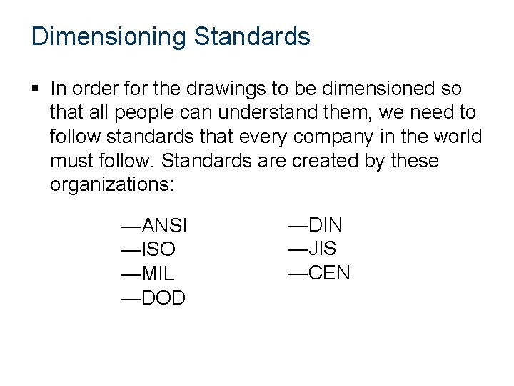
Dimensioning Standards § In order for the drawings to be dimensioned so that all people can understand them, we need to follow standards that every company in the world must follow. Standards are created by these organizations: —ANSI —ISO —MIL —DOD —DIN —JIS —CEN
Standards Institutions • ANSI - American National Standards Institute. This institute creates the engineering standards for North America. • ISO - International Organization for Standardization. This is a worldwide organization that creates engineering standards with approximately 100 participating countries.
Standards Institutions • The United States military has two organizations that develop standards. – DOD - Department Of Defense ‒ MIL - Military Standard
Standards Institutions • DIN - Deutsches Institut für Normung. The German Standards Institute created many standards used worldwide, including the standards for camera film. • JIS - Japanese Industrial Standard. Created after WWII for Japanese standards. • CEN - European Standards Organization.
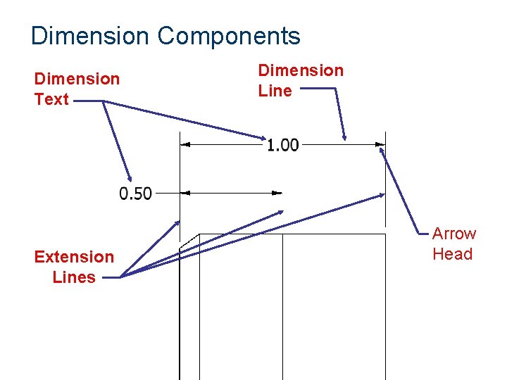
Dimension Components Dimension Text Extension Lines Dimension Line Arrow Head
Dimension Text Guidelines If the dimension text will not fit between the extension lines, it may be placed outside them
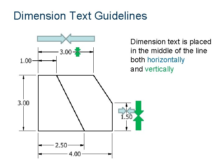
Dimension Text Guidelines Dimension text is placed in the middle of the line both horizontally and vertically
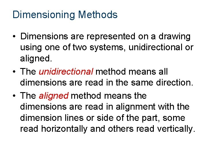
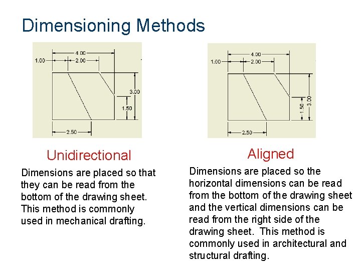
Dimensioning Methods • Dimensions are represented on a drawing using one of two systems, unidirectional or aligned. • The unidirectional method means all dimensions are read in the same direction. • The aligned method means the dimensions are read in alignment with the dimension lines or side of the part, some read horizontally and others read vertically.
Dimensioning Methods Unidirectional Aligned Dimensions are placed so that they can be read from the bottom of the drawing sheet. This method is commonly used in mechanical drafting. Dimensions are placed so the horizontal dimensions can be read from the bottom of the drawing sheet and the vertical dimensions can be read from the right side of the drawing sheet. This method is commonly used in architectural and structural drafting.
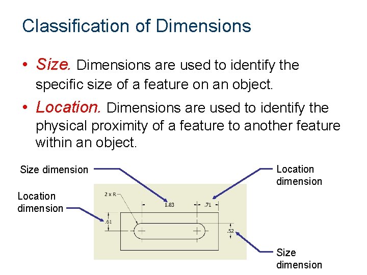
Classification of Dimensions • Size. Dimensions are used to identify the specific size of a feature on an object. • Location. Dimensions are used to identify the physical proximity of a feature to another feature within an object. Size dimension Location dimension Size dimension
Linear Dimensioning • Chain Dimensioning – Dimensioning from feature to feature – Common dimensioning technique
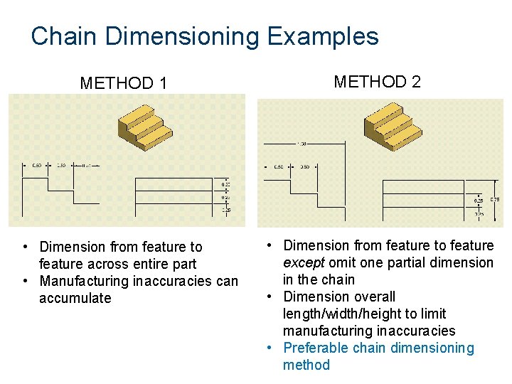
Chain Dimensioning Examples METHOD 1 • Dimension from feature to feature across entire part • Manufacturing inaccuracies can accumulate METHOD 2 • Dimension from feature to feature except omit one partial dimension in the chain • Dimension overall length/width/height to limit manufacturing inaccuracies • Preferable chain dimensioning method
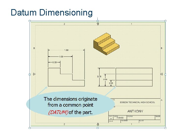
Datum Dimensioning • Datum Dimensioning – Dimensioning from a single point of origin called a DATUM – Reduces dimensional deviations in manufactured parts because each size/location dimension is referenced to a single point
Datum Dimensioning
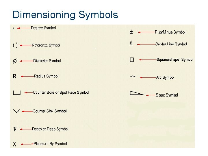
Dimensioning Symbols
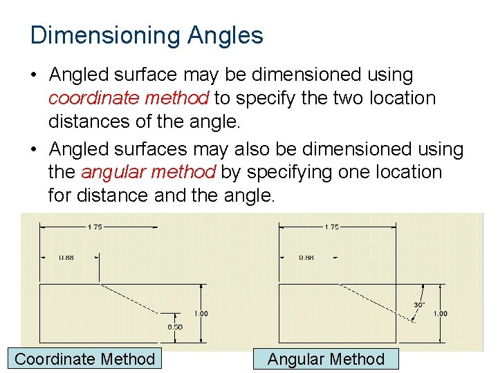
Dimensioning Angles • Angled surface may be dimensioned using coordinate method to specify the two location distances of the angle. • Angled surfaces may also be dimensioned using the angular method by specifying one location for distance and the angle. Coordinate Method Angular Method
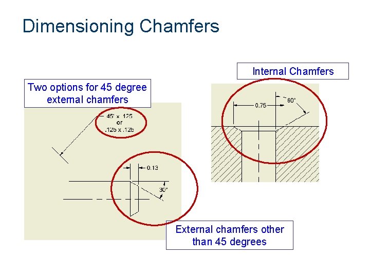
Dimensioning Chamfers Internal Chamfers Two options for 45 degree external chamfers External chamfers other than 45 degrees
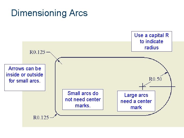
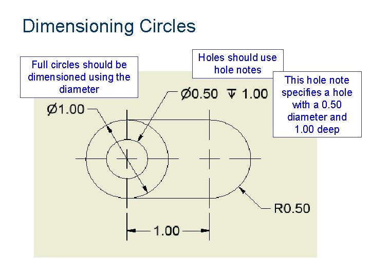
Dimensioning Arcs and Circles • Arcs and circles are dimensioned in views that show the arc or circle. • Arcs are dimensioned with a leader to identify the radius; in some cases, a center mark is included. • Circles should have a center mark and are dimensioned with a leader to identify the diameter.
Dimensioning Arcs Use a capital R to indicate radius Arrows can be inside or outside for small arcs. Small arcs do not need center marks. Large arcs need a center mark
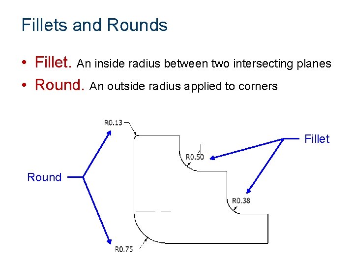
Fillets and Rounds • Fillet. An inside radius between two intersecting planes • Round. An outside radius applied to corners Fillet Round
Dimensioning Circles Full circles should be dimensioned using the diameter Holes should use hole notes This hole note specifies a hole with a 0. 50 diameter and 1. 00 deep
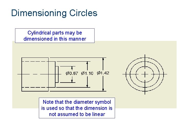
Dimensioning Circles Cylindrical parts may be dimensioned in this manner Note that the diameter symbol is used so that the dimension is not assumed to be linear
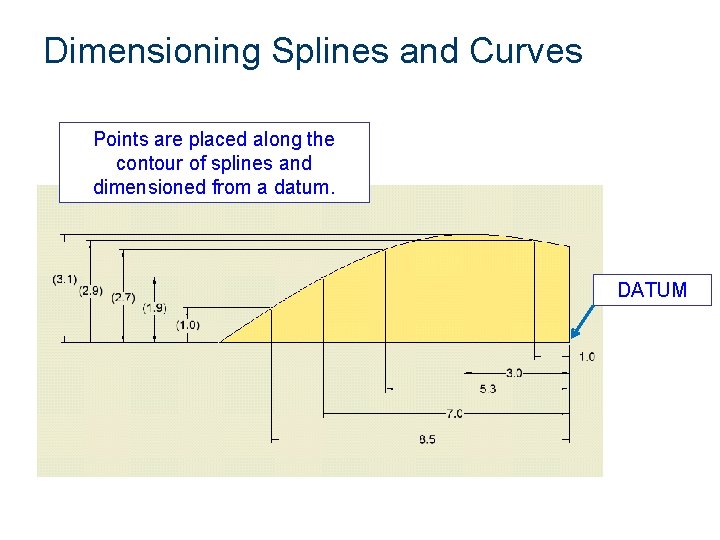
Dimensioning Splines and Curves Points are placed along the contour of splines and dimensioned from a datum. DATUM
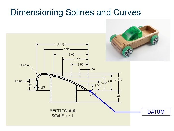
Dimensioning Splines and Curves DATUM
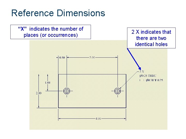
Reference Dimensions “X” indicates the number of places (or occurrences) 2 X indicates that there are two identical holes
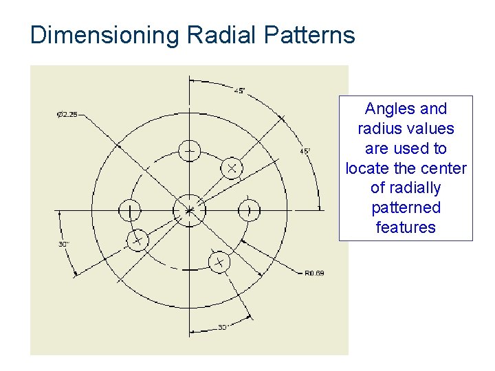
Dimensioning Radial Patterns Angles and radius values are used to locate the center of radially patterned features