Digitaltoanalog modulation Types of digitaltoanalog modulation Amplitude Shift

 On/Off keying • • The amplitude of the carrier signal")


 method")
")
 COS SIN 45 +0. 707 135 -0. 707 +0. 707 225")
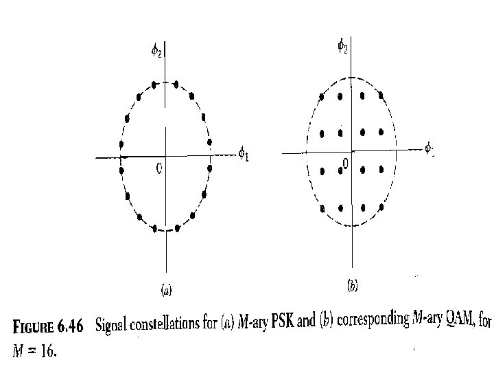
 SIGNAL SPACE DIAGRAM")
")
 a 2=+√(E/2) (or)-√(E/2)")


 -135 ØCan")


- Slides: 39
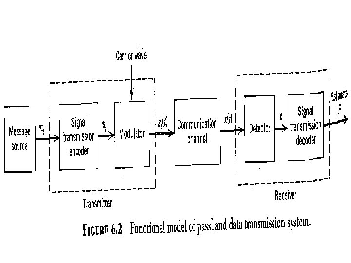
Digital-to-analog modulation Types of digital-to-analog modulation
Amplitude Shift Keying (ASK) On/Off keying • • The amplitude of the carrier signal is varied to represent binary 1 & 0. Frequency and phase remains the same. Highly susceptible to noise interference. Used up to 1200 bps on voice grade lines, and on optical fiber.
Frequency Shift Keying • Frequency of the carrier is varied to represent digital data (binary 0/1) • Peak amplitude and phase remain constant. • Avoid noise interference by looking at frequencies (change of a signal) and ignoring amplitudes. • Limitations of FSK is the physical capabilities of the carrier. • f 1 and f 2 equally offset by equal opposite amounts to the carrier freq. • In MFSK more than 2 freq are used, each signal element represents more than one bit
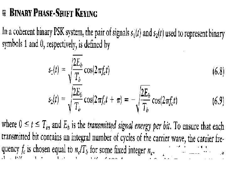
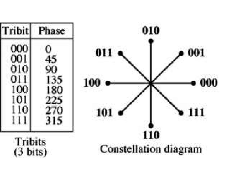
Phase Shift Keying • • Phase of the carrier is varied to represent digital data (binary 0 or 1) Amplitude and frequency remains constant. If phase 0 deg to represent 0, 180 deg to represent 1. (2 -PSK) PSK is not susceptible to noise degradation that affects ASK or bandwidth limitations of FSK
BPSK TRANSMITTER BPSK RECEIVER
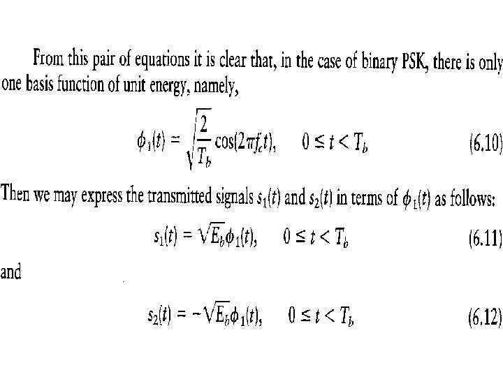
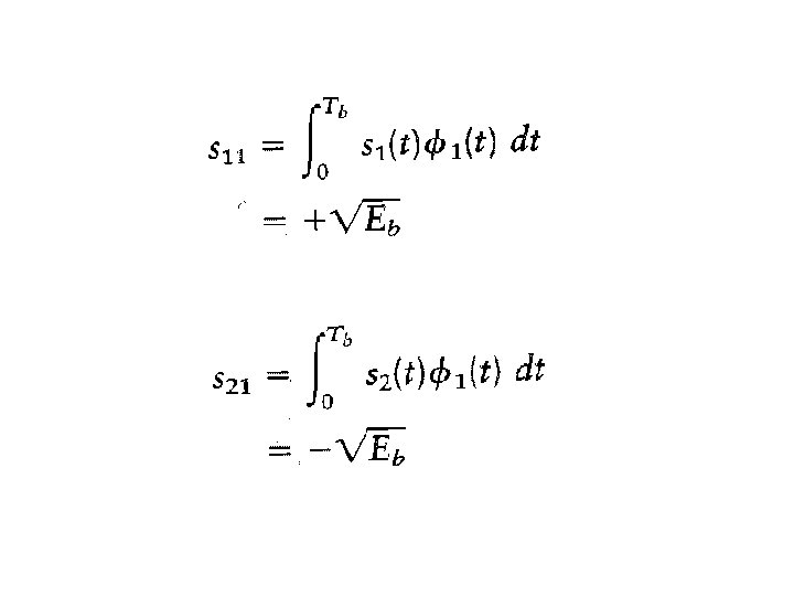
Signal space diagram of BPSK
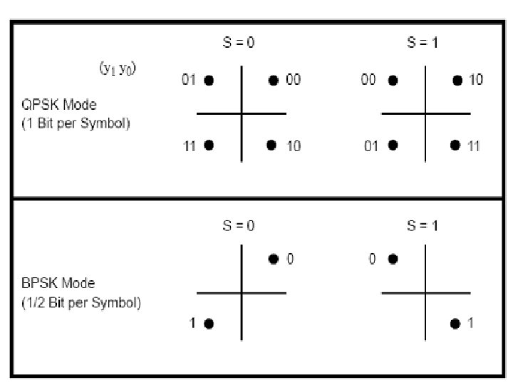
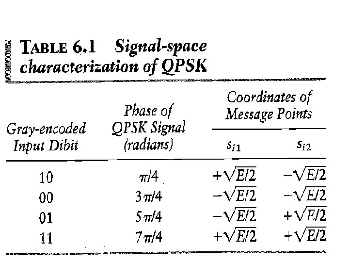
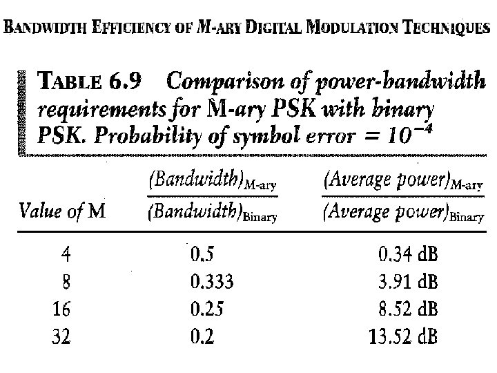
4 -PSK (QPSK) method
4 -PSK (QPSK)
4 -PSK (QPSK) COS SIN 45 +0. 707 135 -0. 707 +0. 707 225 -0. 707 315 +0. 707 -0. 707
4 -PSK (QPSK) SIGNAL SPACE DIAGRAM
4 -PSK (QPSK)
QPSK TRANSMITTER a 1 (or) a 2=+√(E/2) (or)-√(E/2)
QPSK RECEIVER
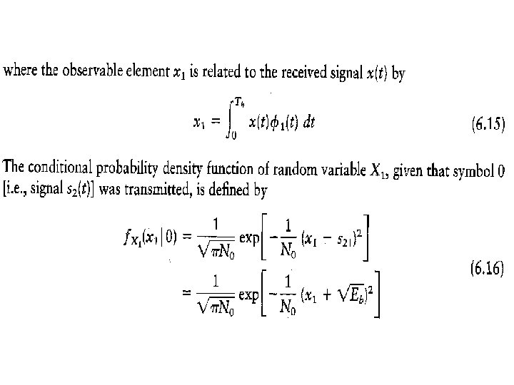
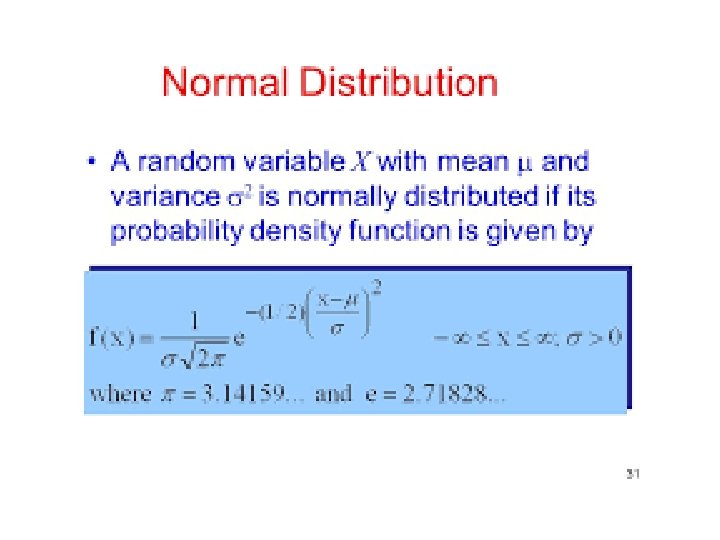
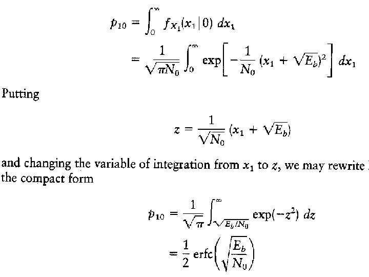
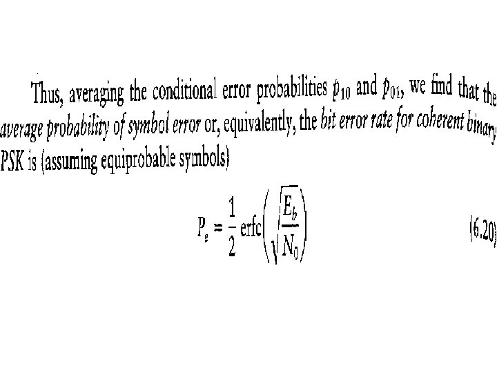
DERIVATION-PROBABILITY OF ERROR IN QPSK
DERIVATION-PROBABILITY OF ERROR IN QPSK
DERIVATION-PROBABILITY OF ERROR IN QPSK
DERIVATION-PROBABILITY OF ERROR IN QPSK
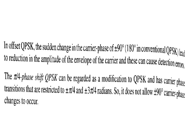
Offset QPSK waveforms • Presence of 180 degree phase shift in QPSK makes the signal to loose constant envelope property. Non linear amplification of such signal causes unwanted side lobes and spectral widening. • In OQPSK maximum phase shift is limited to 90 degree. • Even and Odd bit streams are offset in their relative alignment by one bit period.
Offset QPSK waveforms
Offset QPSK Transmitter
Pi/4 QPSK signaling ØMaximum phase angle change is limited to +135 (or) -135 ØCan be noncoherently detected
Pi/4 QPSK phase shifts
Possible values of Øk are +45, -45, +135, -135
Pi/4 QPSK transmitter
Differential detection of pi/4 QPSK