
Digital transmission fundamentals chap 3 4 1 What







- Slides: 45
Digital transmission fundamentals (chap. 3 & 4) 1. What is digital transmission? 2. Why digital transmission? 3. How to represent different information in digital format? 4. What is Bit rate/bandwidth? 5. What are the properties of different media? 6. How to do error detection and correction? 7. Multiplexing? CIS, IUPUI 1
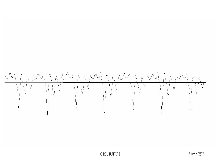
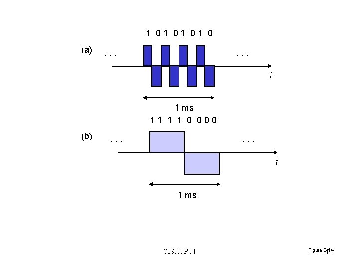
What is digital transmission? • Analog transmission – Continuous waveform • Digital representation and transmission – Discrete binary sequence/pulses – 1: a rectangular pulse of amplitude 1 and of duration 0. 125 milliseconds – 0: a rectangular pulse of amplitude -1 and of duration of 0. 125 milliseconds. CIS, IUPUI 2
CIS, IUPUI Figure 3. 13 3
1 01 0 (a) . . . t 1 ms 11 1 1 0 000 (b) . . . t 1 ms CIS, IUPUI Figure 3. 14 4
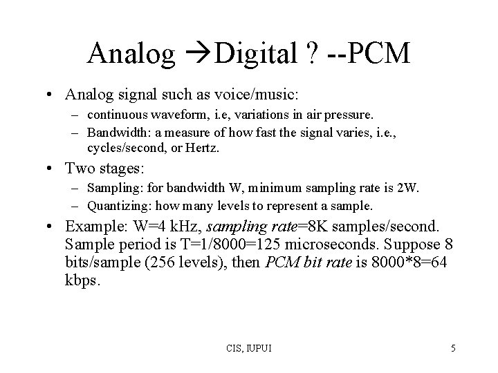
Analog Digital ? --PCM • Analog signal such as voice/music: – continuous waveform, i. e, variations in air pressure. – Bandwidth: a measure of how fast the signal varies, i. e. , cycles/second, or Hertz. • Two stages: – Sampling: for bandwidth W, minimum sampling rate is 2 W. – Quantizing: how many levels to represent a sample. • Example: W=4 k. Hz, sampling rate=8 K samples/second. Sample period is T=1/8000=125 microseconds. Suppose 8 bits/sample (256 levels), then PCM bit rate is 8000*8=64 kbps. CIS, IUPUI 5
(a) 7 D/2 5 D/2 3 D/2 5 D/2 7 D/2 (b) 7 D/2 5 D/2 3 D/2 5 D/2 7 D/2 CIS, IUPUI 6 Figure 3. 2
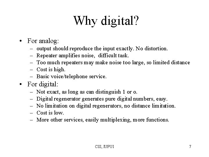
Why digital? • For analog: – – – output should reproduce the input exactly. No distortion. Repeater amplifies noise, difficult task. Too much repeaters may make noise too large, so limited distance Cost is high. Basic voice/telephone service. • For digital: – – – Not exact, as long as can distinguish 1 or o. Digital regenerator generates pure digital numbers, easy. No limitation on digital regenerators, no distance limitation. Cost is low. More other services, easily multiplexing, more functions. CIS, IUPUI 7
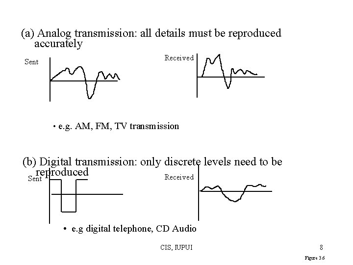
(a) Analog transmission: all details must be reproduced accurately Sent Received • e. g. AM, FM, TV transmission (b) Digital transmission: only discrete levels need to be reproduced Received Sent • e. g digital telephone, CD Audio CIS, IUPUI 8 Figure 3. 6
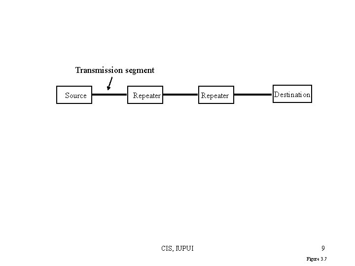
Transmission segment Source Repeater CIS, IUPUI Destination 9 Figure 3. 7
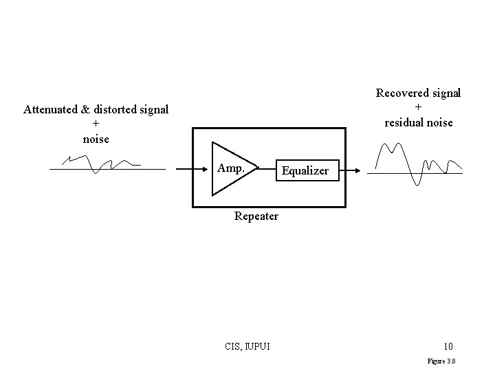
Recovered signal + residual noise Attenuated & distorted signal + noise Amp. Equalizer Repeater CIS, IUPUI 10 Figure 3. 8
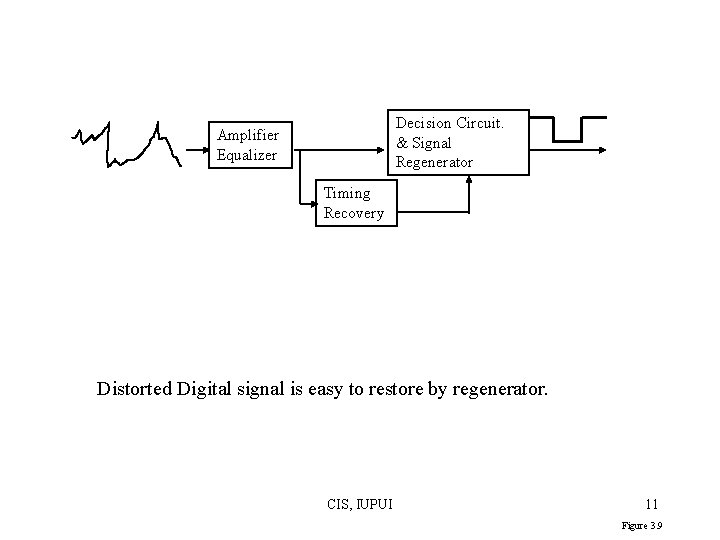
Decision Circuit. & Signal Regenerator Amplifier Equalizer Timing Recovery Distorted Digital signal is easy to restore by regenerator. CIS, IUPUI 11 Figure 3. 9
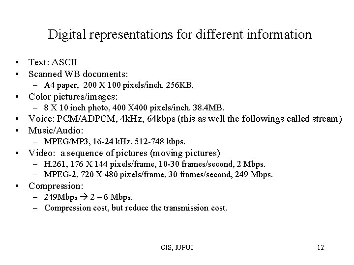
Digital representations for different information • Text: ASCII • Scanned WB documents: – A 4 paper, 200 X 100 pixels/inch. 256 KB. • Color pictures/images: – 8 X 10 inch photo, 400 X 400 pixels/inch. 38. 4 MB. • Voice: PCM/ADPCM, 4 k. Hz, 64 kbps (this as well the followings called stream) • Music/Audio: – MPEG/MP 3, 16 -24 k. Hz, 512 -748 kbps. • Video: a sequence of pictures (moving pictures) – H. 261, 176 X 144 pixels/frame, 10 -30 frames/second, 2 Mbps. – MPEG-2, 720 X 480 pixels/frame, 30 frames/second, 249 Mbps. • Compression: – 249 Mbps 2 – 6 Mbps. – Compression cost, but reduce the transmission cost. CIS, IUPUI 12
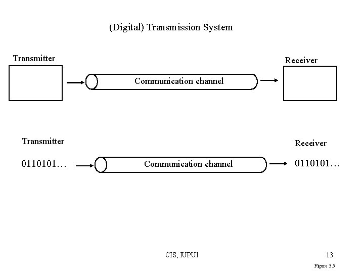
(Digital) Transmission System Transmitter Receiver Communication channel Transmitter 0110101… Receiver Communication channel CIS, IUPUI 0110101… 13 Figure 3. 5
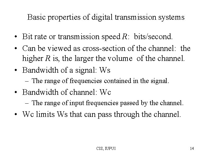
Basic properties of digital transmission systems • Bit rate or transmission speed R: bits/second. • Can be viewed as cross-section of the channel: the higher R is, the larger the volume of the channel. • Bandwidth of a signal: Ws – The range of frequencies contained in the signal. • Bandwidth of channel: Wc – The range of input frequencies passed by the channel. • Wc limits Ws that can pass through the channel. CIS, IUPUI 14
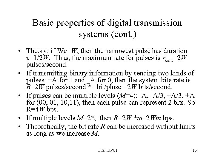
Basic properties of digital transmission systems (cont. ) • Theory: if Wc=W, then the narrowest pulse has duration =1/2 W. Thus, the maximum rate for pulses is rmax=2 W pulses/second. • If transmitting binary information by sending two kinds of pulses: +A for 1 and _A for 0, then the system bite rate is R=2 W pulses/second * 1 bit/pluse =2 W bits/second. • If pulses can be multiple levels (M=4): -A, -A/3, +A for (00, 01, 10, 11), then each pulse can represent 2 bits. So R=4 W bps. • If multiple levels M=2 m, then R=2 W *m=2 Wm bps. • Theoretically, the bit rate R can be increased without limits as long as we increase M. CIS, IUPUI 15
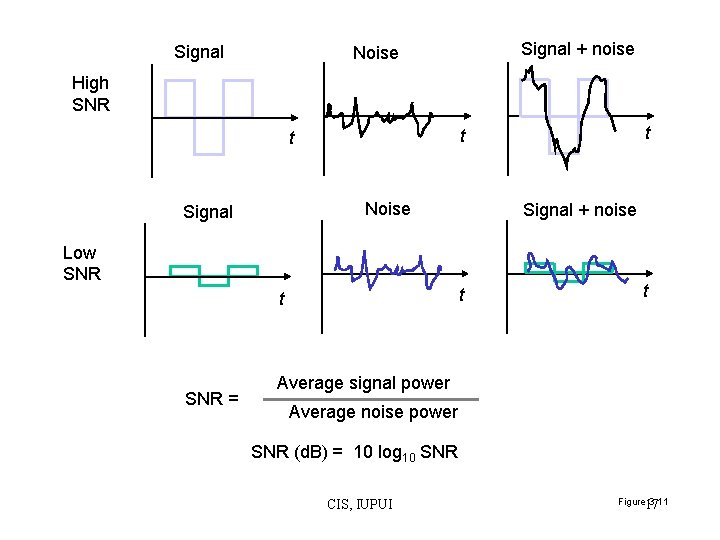
Shannon Channel Capacity • Unfortunately, in practice, R is greatly limited: – Levels can not be measured accurately if too many levels. – there exists noise in real world. • Signal –to-noise ratio SNR= average signal power/average noise power. • SNR(d. B)=10 log 10 SNR (decibels). • So Shannon Channel Capacity: – C (i. e. , maximum reliable bite rate R ) – = W log 2(1+SNR) bits/second. CIS, IUPUI 16
Signal + noise Noise High SNR Noise Signal + noise Low SNR t t SNR = t t Average signal power Average noise power SNR (d. B) = 10 log 10 SNR CIS, IUPUI Figure 17 3. 11
Typical noise Four signal levels Eight signal levels When too many levels: 1. difficult to measure 2. noise will easily affect the value. CIS, IUPUI Figure 18 3. 32
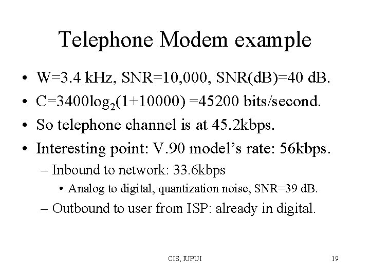
Telephone Modem example • • W=3. 4 k. Hz, SNR=10, 000, SNR(d. B)=40 d. B. C=3400 log 2(1+10000) =45200 bits/second. So telephone channel is at 45. 2 kbps. Interesting point: V. 90 model’s rate: 56 kbps. – Inbound to network: 33. 6 kbps • Analog to digital, quantization noise, SNR=39 d. B. – Outbound to user from ISP: already in digital. CIS, IUPUI 19
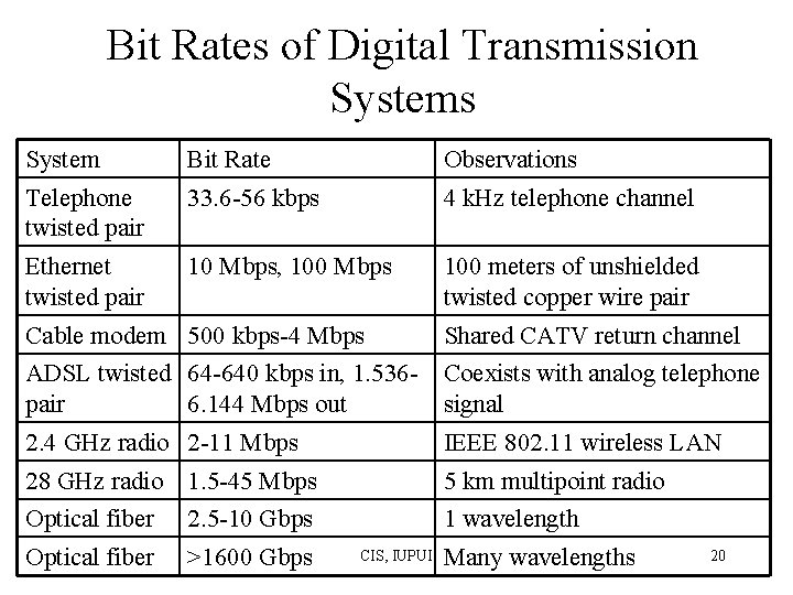
Bit Rates of Digital Transmission Systems System Bit Rate Observations Telephone twisted pair 33. 6 -56 kbps 4 k. Hz telephone channel Ethernet twisted pair 10 Mbps, 100 Mbps 100 meters of unshielded twisted copper wire pair Cable modem 500 kbps-4 Mbps Shared CATV return channel ADSL twisted 64 -640 kbps in, 1. 536 pair 6. 144 Mbps out Coexists with analog telephone signal 2. 4 GHz radio 2 -11 Mbps IEEE 802. 11 wireless LAN 28 GHz radio 1. 5 -45 Mbps 5 km multipoint radio Optical fiber 2. 5 -10 Gbps 1 wavelength Optical fiber >1600 Gbps CIS, IUPUI Many wavelengths 20
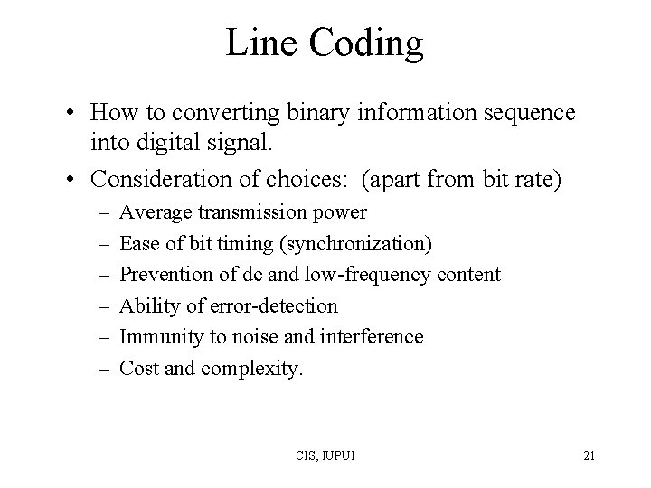
Line Coding • How to converting binary information sequence into digital signal. • Consideration of choices: (apart from bit rate) – – – Average transmission power Ease of bit timing (synchronization) Prevention of dc and low-frequency content Ability of error-detection Immunity to noise and interference Cost and complexity. CIS, IUPUI 21
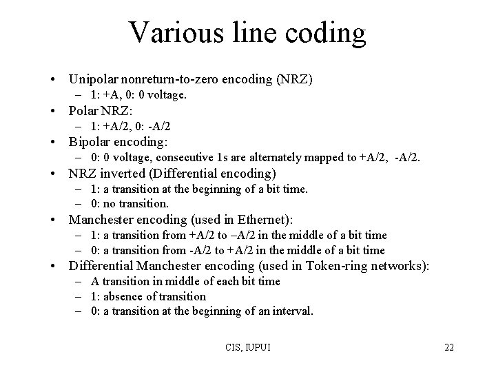
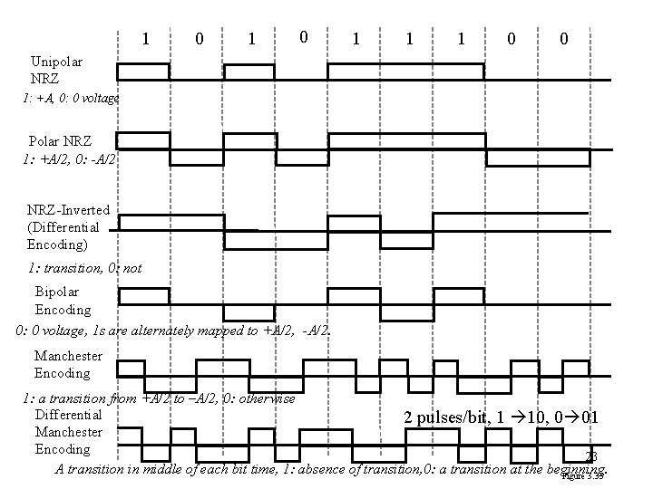
Various line coding • Unipolar nonreturn-to-zero encoding (NRZ) – 1: +A, 0: 0 voltage. • Polar NRZ: – 1: +A/2, 0: -A/2 • Bipolar encoding: – 0: 0 voltage, consecutive 1 s are alternately mapped to +A/2, -A/2. • NRZ inverted (Differential encoding) – 1: a transition at the beginning of a bit time. – 0: no transition. • Manchester encoding (used in Ethernet): – 1: a transition from +A/2 to –A/2 in the middle of a bit time – 0: a transition from -A/2 to +A/2 in the middle of a bit time • Differential Manchester encoding (used in Token-ring networks): – A transition in middle of each bit time – 1: absence of transition – 0: a transition at the beginning of an interval. CIS, IUPUI 22
1 0 1 1 1 0 0 Unipolar NRZ 1: +A, 0: 0 voltage Polar NRZ 1: +A/2, 0: -A/2 NRZ-Inverted (Differential Encoding) 1: transition, 0: not Bipolar Encoding 0: 0 voltage, 1 s are alternately mapped to +A/2, -A/2. Manchester Encoding 1: a transition from +A/2 to –A/2, 0: otherwise Differential 2 pulses/bit, 1 10, 0 01 Manchester Encoding 23 A transition in middle of each bit time, 1: absence of transition, 0: a transition at the beginning. Figure 3. 35
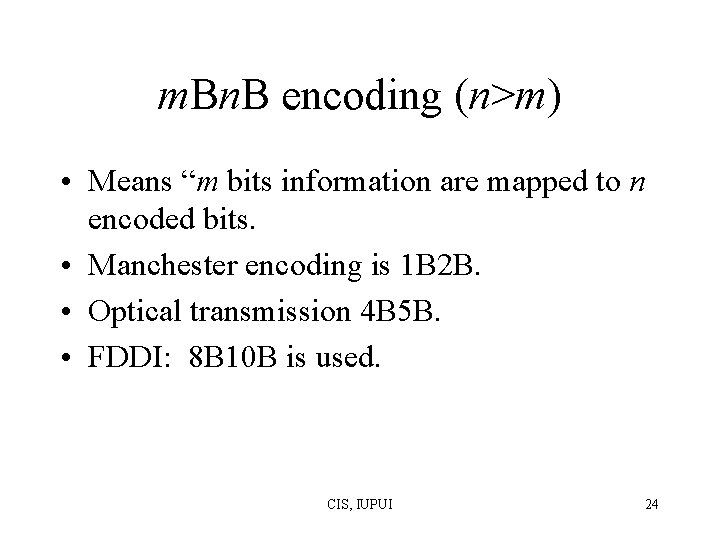
m. Bn. B encoding (n>m) • Means “m bits information are mapped to n encoded bits. • Manchester encoding is 1 B 2 B. • Optical transmission 4 B 5 B. • FDDI: 8 B 10 B is used. CIS, IUPUI 24
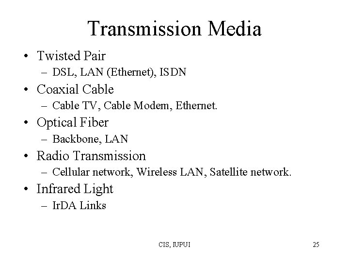
Transmission Media • Twisted Pair – DSL, LAN (Ethernet), ISDN • Coaxial Cable – Cable TV, Cable Modem, Ethernet. • Optical Fiber – Backbone, LAN • Radio Transmission – Cellular network, Wireless LAN, Satellite network. • Infrared Light – Ir. DA Links CIS, IUPUI 25
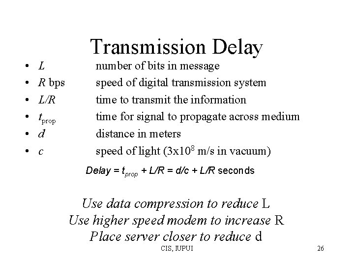
Transmission Delay • • • L R bps L/R tprop d c number of bits in message speed of digital transmission system time to transmit the information time for signal to propagate across medium distance in meters speed of light (3 x 10⁸ m/s in vacuum) Delay = tprop + L/R = d/c + L/R seconds Use data compression to reduce L Use higher speed modem to increase R Place server closer to reduce d CIS, IUPUI 26
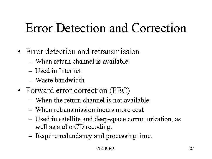
Error Detection and Correction • Error detection and retransmission – When return channel is available – Used in Internet – Waste bandwidth • Forward error correction (FEC) – When the return channel is not available – When retransmission incurs more cost – Used in satellite and deep-space communication, as well as audio CD recoding. – Require redundancy and processing time. CIS, IUPUI 27
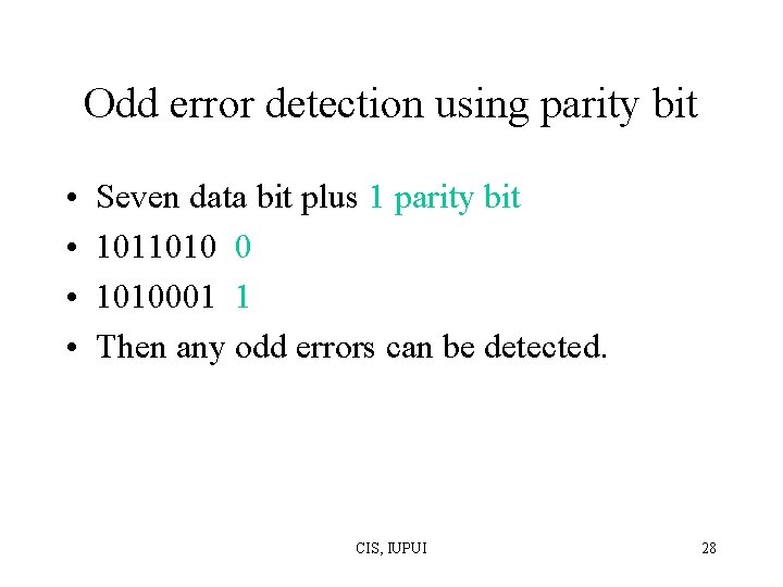
Odd error detection using parity bit • • Seven data bit plus 1 parity bit 1011010 0 1010001 1 Then any odd errors can be detected. CIS, IUPUI 28
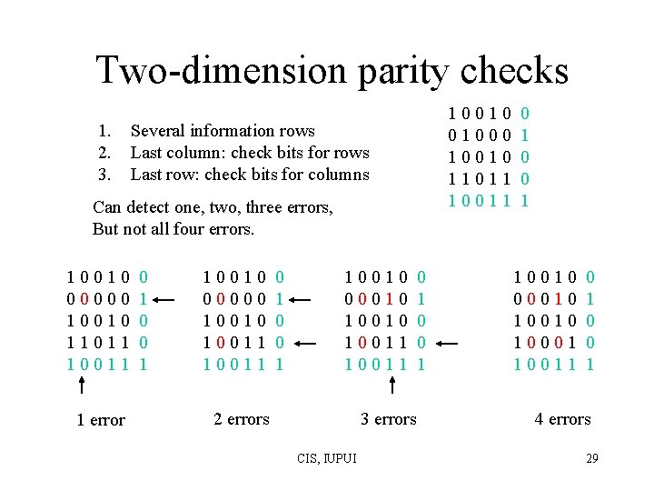
Two-dimension parity checks 1. 2. 3. 10010 01000 10010 11011 10011 Several information rows Last column: check bits for rows Last row: check bits for columns Can detect one, two, three errors, But not all four errors. 10010 00000 10010 11011 10011 1 error 0 1 0 0 1 10010 00000 10011 0 0 1 10010 00010 10011 2 errors 3 errors CIS, IUPUI 0 1 0 0 1 10010 00010 10001 10011 0 0 1 4 errors 29
Internet Checksum • IP packet, a checksum is calculated for the headers and put in a field in the header. • Goal is easy/efficient to implement, make routers simple and efficient. • Suppose m 16 -bit words, b 0, b 1, …, bm-1 – – Compute x= b 0+ b 1+ …+ bm-1 mod 216 -1 Set checksum bm=-x Insert x in the checksum field Verify b 0+ b 1+ …+ bm-1 + bm=0 mod 216 -1. CIS, IUPUI 30
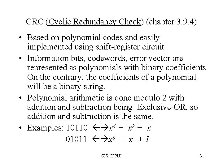
CRC (Cyclic Redundancy Check) (chapter 3. 9. 4) • Based on polynomial codes and easily implemented using shift-register circuit • Information bits, codewords, error vector are represented as polynomials with binary coefficients. On the contrary, the coefficients of a polynomial will be a binary string. • Polynomial arithmetic is done modulo 2 with addition and subtraction being Exclusive-OR, so addition and subtraction is the same. • Examples: 10110 x 4 + x 2 + x 01011 x 3 + x + 1 CIS, IUPUI 31
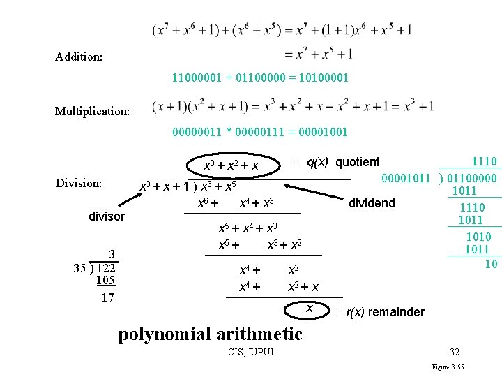
Addition: 11000001 + 01100000 = 10100001 Multiplication: 00000011 * 00000111 = 00001001 x 3 + x 2 + x Division: divisor 3 35 ) 122 105 17 x 3 + x + 1 ) x 6 + x 5 x 6 + x 4 + x 3 x 5 + x 3 + x 2 x 4 + 1110 00001011 ) 01100000 1011 dividend 1110 1011 10 = q(x) quotient x 2 + x x = r(x) remainder polynomial arithmetic CIS, IUPUI 32 Figure 3. 55
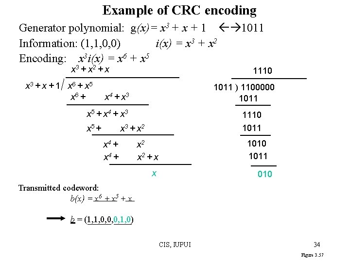
How to compute CRC • There is a generator polynomial, g(x) of degree r, which the sender and receiver agree upon in advance. • Suppose the information transmitted has m bits, i. e. i(x), then sender appends r zero at the end of information, i. e, xr i(x) • Perform xr i(x) / g(x) to get remainder r(x) (and quotient q(x)) • Append the r bit string of r(x) to the end of m bit information to get m+r bit string, i. e. , b(x), for transmission. – b(x) = xr i(x) + r(x) ( =g(x)q(x)+r(x)=g(x)q(x) ) • When receiver receives the bit string, i. e. , b’(x), it will divide b’(x) by g(x) , if the remainder is not zero, then error occurs. --suppose no error occurs, then b’(x) = b(x), so b’(x)/g(x) =b(x)/g(x)=g(x)q(x)/g(x)=q(x), remainder is 0. CIS, IUPUI 33
Example of CRC encoding Generator polynomial: g(x)= x 3 + x + 1 1011 Information: (1, 1, 0, 0) i(x) = x 3 + x 2 Encoding: x 3 i(x) = x 6 + x 5 x 3 + x 2 + x x 3 + x + 1 x 6 + x 5 x 6 + 1110 1011 ) 1100000 1011 x 4 + x 3 x 5 + 1110 1011 x 3 + x 2 x 4 + 1010 1011 x 2 + x x 010 Transmitted codeword: b(x) = x 6 + x 5 + x b = (1, 1, 0, 0, 0, 1, 0) CIS, IUPUI 34 Figure 3. 57
Example of CRC encoding (cont. ) If 1100010 is received, then 1100010 is divided by 1011, The remainder will be zero (please verify yourself), so no error. Suppose 1101010 is received, then let us do the division as follows: 1111 1011 ) 1101010 1011 1100 1011 1111 1000 1011 11 CIS, IUPUI The remainder is not zero, so error occurs. 35
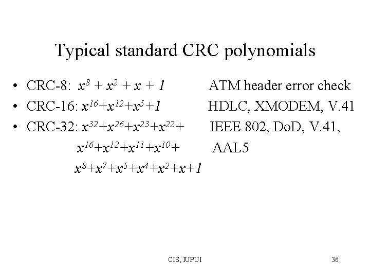
Typical standard CRC polynomials • CRC-8: x 8 + x 2 + x + 1 • CRC-16: x 16+x 12+x 5+1 • CRC-32: x 32+x 26+x 23+x 22+ x 16+x 12+x 11+x 10+ x 8+x 7+x 5+x 4+x 2+x+1 CIS, IUPUI ATM header error check HDLC, XMODEM, V. 41 IEEE 802, Do. D, V. 41, AAL 5 36
Analysis of error detection power Received poly: R(x)= b(x) +e(x), where e(x) is error poly. 0 i n-1 1. Single errors: e(x) = xi If g(x) has more than one term, it cannot divide e(x) 2. Double errors: e(x) = xi + xj 0 i < j n-1 = xi (1 + xj-i ) If g(x) is primitive, it will not divide (1 + xj-i ) for j-i 2 n-k 1 3. Odd number of errors: e(1) =1. If g(x) has (x+1) as a factor, then g(1) = 0 and all codewords have an even number of 1 s. CIS, IUPUI 37 Figure 3. 60
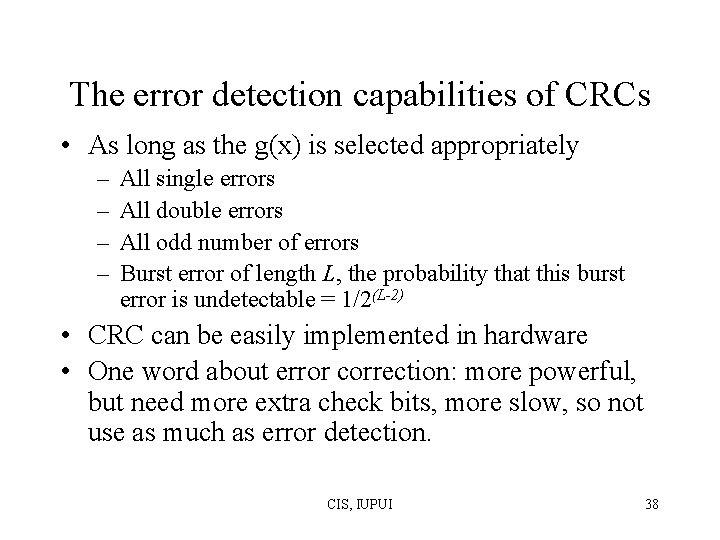
The error detection capabilities of CRCs • As long as the g(x) is selected appropriately – – All single errors All double errors All odd number of errors Burst error of length L, the probability that this burst error is undetectable = 1/2(L-2) • CRC can be easily implemented in hardware • One word about error correction: more powerful, but need more extra check bits, more slow, so not use as much as error detection. CIS, IUPUI 38
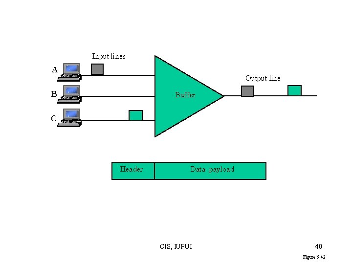
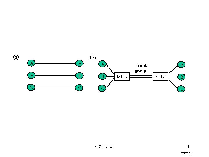
Statistical multiplexing • Burst feature of user interactions makes dedicated communication lines inefficient • Multiplexing multiple lines into one line which has generally more bandwidth. • In order for coordinating the usage of the shared line, buffers are needed. • Multiplexers are introduced for multiplexing CIS, IUPUI 39
Input lines A Output line B Buffer C Header Data payload CIS, IUPUI 40 Figure 5. 42
(a) (b) A A A B B B C CIS, IUPUI A Trunk group MUX B C 41 Figure 4. 1
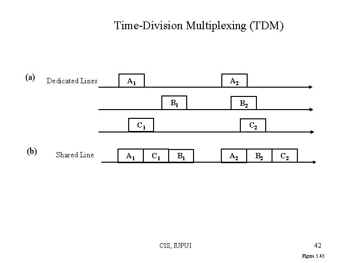
Time-Division Multiplexing (TDM) (a) Dedicated Lines A 1 A 2 B 1 B 2 C 1 (b) Shared Line A 1 C 2 C 1 B 1 CIS, IUPUI A 2 B 2 C 2 42 Figure 5. 43
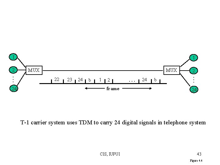
1 24 MUX 22 23 24 b 1 2 frame . . . 24 b 2. . . 2 1 24 T-1 carrier system uses TDM to carry 24 digital signals in telephone system CIS, IUPUI 43 Figure 4. 4
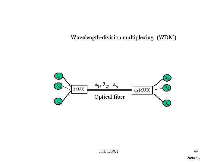
Wavelength-division multiplexing (WDM) 1 2 n MUX 1 , 2 , n Optical fiber CIS, IUPUI 1 de. MUX 2 n 44 Figure 4. 1
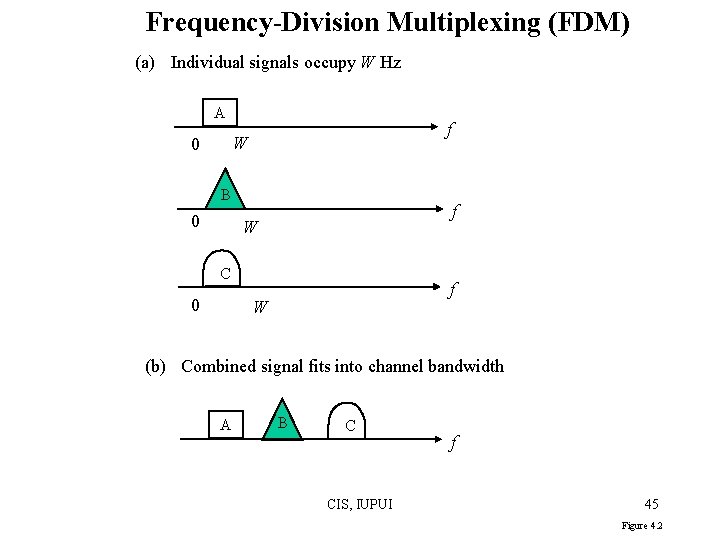
Frequency-Division Multiplexing (FDM) (a) Individual signals occupy W Hz A f W 0 B 0 f W C 0 f W (b) Combined signal fits into channel bandwidth A B C CIS, IUPUI f 45 Figure 4. 2