
Digital Systems Lecture 3 Dr Ing Erwin Sitompul
- Slides: 35
Digital Systems Lecture 3 Dr. -Ing. Erwin Sitompul President University http: //zitompul. wordpress. com 2 0 1 5 President University Erwin Sitompul Digital Systems 3/1
Digital Systems Section 4 Logic Gates President University Erwin Sitompul Digital Systems 3/2
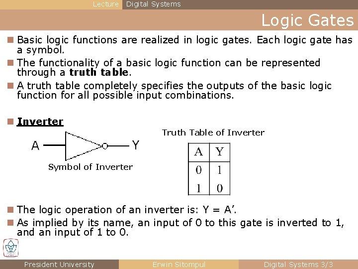
Lecture Digital Systems Logic Gates n Basic logic functions are realized in logic gates. Each logic gate has a symbol. n The functionality of a basic logic function can be represented through a truth table. n A truth table completely specifies the outputs of the basic logic function for all possible input combinations. n Inverter Truth Table of Inverter Y A Symbol of Inverter n The logic operation of an inverter is: Y = A’. n As implied by its name, an input of 0 to this gate is inverted to 1, and an input of 1 to 0. President University Erwin Sitompul Digital Systems 3/3
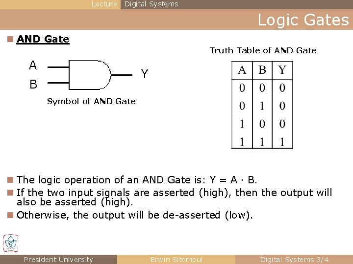
Lecture Digital Systems Logic Gates n AND Gate Truth Table of AND Gate A Y B Symbol of AND Gate n The logic operation of an AND Gate is: Y = A · B. n If the two input signals are asserted (high), then the output will also be asserted (high). n Otherwise, the output will be de-asserted (low). President University Erwin Sitompul Digital Systems 3/4
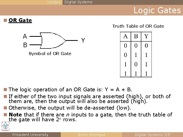
Lecture Digital Systems Logic Gates n OR Gate Truth Table of OR Gate A B Y Symbol of OR Gate n The logic operation of an OR Gate is: Y = A + B. n If either of the two input signals are asserted (high), or both of them are, then the output will also be asserted (high). n Otherwise, the output will be de-asserted (low). n Note that if there are n inputs to a gate, then the truth table of the gate will have 2 n rows. President University Erwin Sitompul Digital Systems 3/5
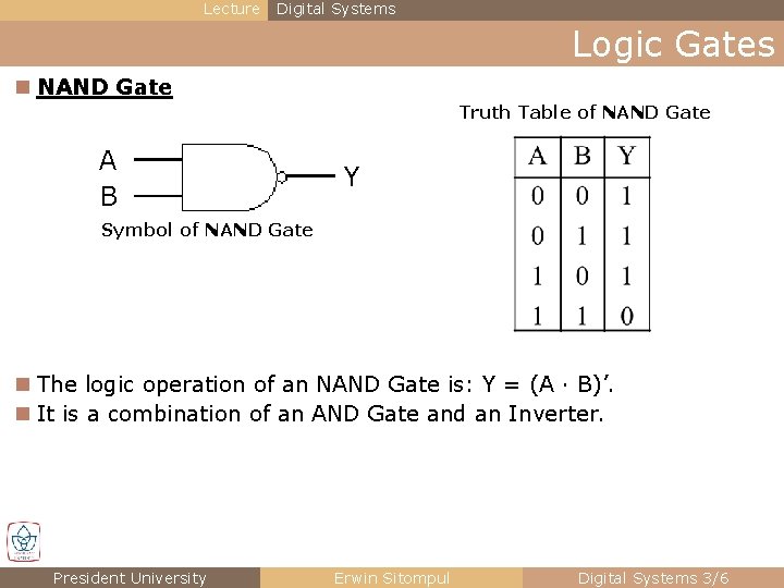
Lecture Digital Systems Logic Gates n NAND Gate Truth Table of NAND Gate A B Y Symbol of NAND Gate n The logic operation of an NAND Gate is: Y = (A · B)’. n It is a combination of an AND Gate and an Inverter. President University Erwin Sitompul Digital Systems 3/6
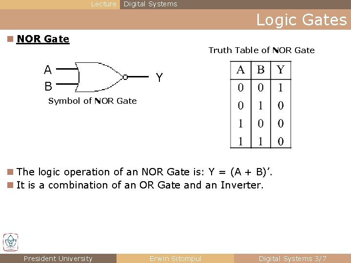
Lecture Digital Systems Logic Gates n NOR Gate Truth Table of NOR Gate A B Y Symbol of NOR Gate n The logic operation of an NOR Gate is: Y = (A + B)’. n It is a combination of an OR Gate and an Inverter. President University Erwin Sitompul Digital Systems 3/7
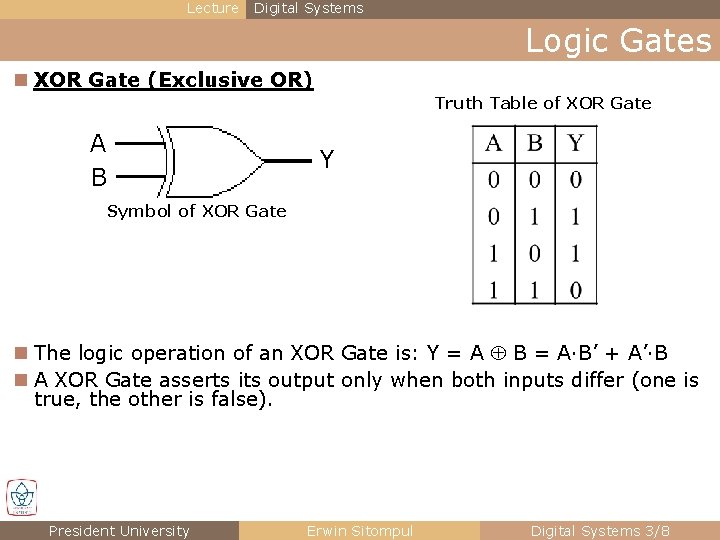
Lecture Digital Systems Logic Gates n XOR Gate (Exclusive OR) Truth Table of XOR Gate A B Y Symbol of XOR Gate n The logic operation of an XOR Gate is: Y = A B = A·B’ + A’·B n A XOR Gate asserts its output only when both inputs differ (one is true, the other is false). President University Erwin Sitompul Digital Systems 3/8
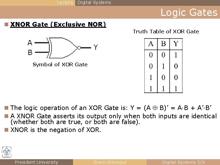
Lecture Digital Systems Logic Gates n XNOR Gate (Exclusive NOR) Truth Table of XOR Gate Symbol of XOR Gate n The logic operation of an XOR Gate is: Y = (A B)’ = A·B + A’·B’ n A XNOR Gate asserts its output only when both inputs are identical (whether both are true, or both are false). n XNOR is the negation of XOR. President University Erwin Sitompul Digital Systems 3/9
Digital Systems Section 5 Combinatorial Logic President University Erwin Sitompul Digital Systems 3/10
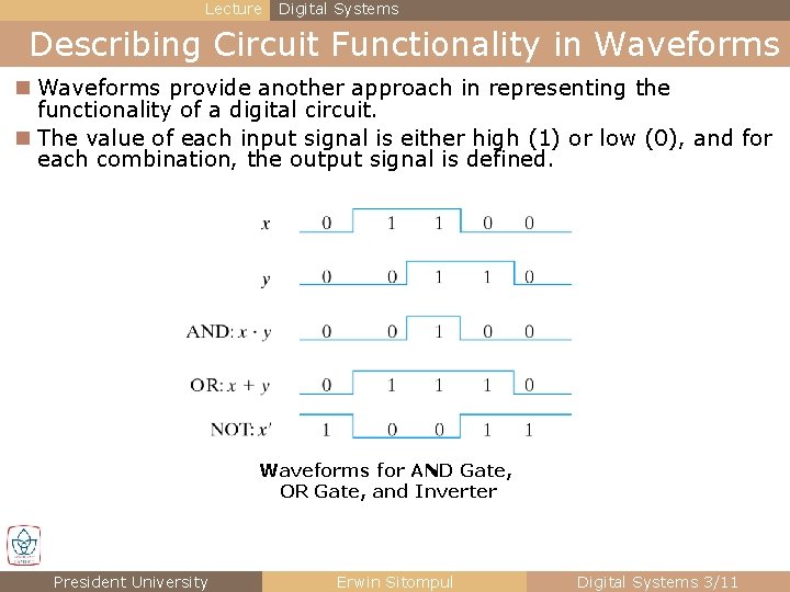
Lecture Digital Systems Describing Circuit Functionality in Waveforms provide another approach in representing the functionality of a digital circuit. n The value of each input signal is either high (1) or low (0), and for each combination, the output signal is defined. Waveforms for AND Gate, OR Gate, and Inverter President University Erwin Sitompul Digital Systems 3/11
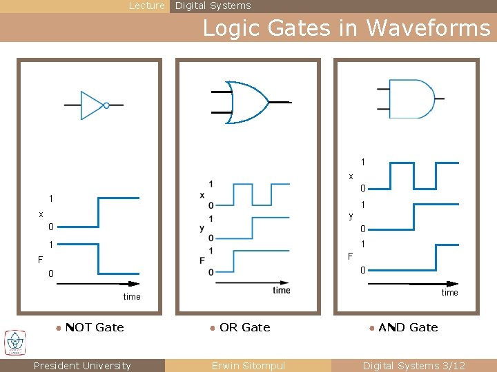
Lecture Digital Systems Logic Gates in Waveforms 1 x 0 1 1 x y 0 0 1 1 F F 0 0 time ● NOT Gate President University ● OR Gate Erwin Sitompul ● AND Gate Digital Systems 3/12
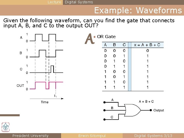
Lecture Digital Systems Example: Waveforms Given the following waveform, can you find the gate that connects input A, B, and C to the output OUT? A ● OR Gate President University Erwin Sitompul Digital Systems 3/13
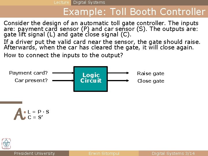
Lecture Digital Systems Example: Toll Booth Controller Consider the design of an automatic toll gate controller. The inputs are: payment card sensor (P) and car sensor (S). The outputs are: gate lift signal (L) and gate close signal (C). If a driver put the valid card near the sensor, the gate should raise. Afterwards, when the car has cleared the gate, it will close again. How to connect the inputs to the output? Payment card? Car present? Logic Circuit Raise gate Close gate A ●L=P·S ● C = S’ President University Erwin Sitompul Digital Systems 3/14
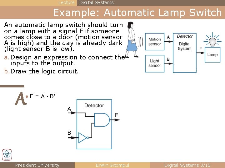
Lecture Digital Systems Example: Automatic Lamp Switch An automatic lamp switch should turn on a lamp with a signal F if someone comes close to a door (motion sensor A is high) and the day is already dark (light sensor B is low). a. Design an expression to connect the inputs to the output. b. Draw the logic circuit. A ● F = A · B’ President University Erwin Sitompul Digital Systems 3/15
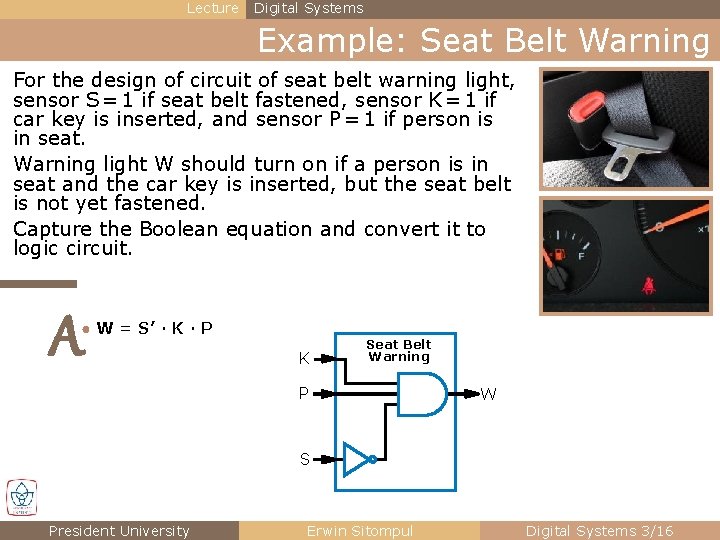
Lecture Digital Systems Example: Seat Belt Warning For the design of circuit of seat belt warning light, sensor S = 1 if seat belt fastened, sensor K = 1 if car key is inserted, and sensor P = 1 if person is in seat. Warning light W should turn on if a person is in seat and the car key is inserted, but the seat belt is not yet fastened. Capture the Boolean equation and convert it to logic circuit. A ● W = S’ · K · P K Seat Belt Warning P W S President University Erwin Sitompul Digital Systems 3/16
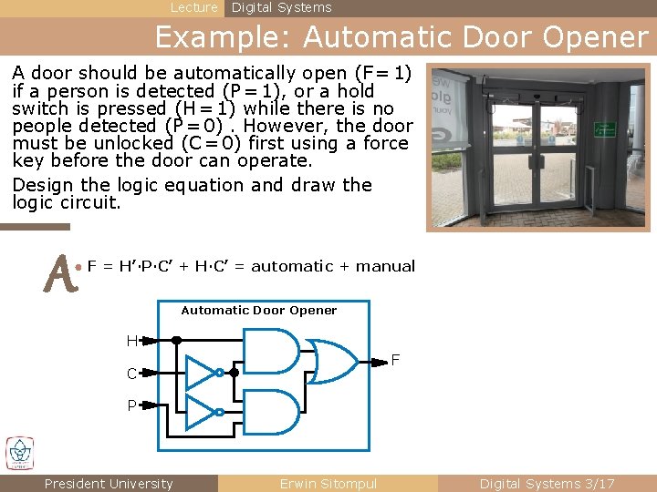
Lecture Digital Systems Example: Automatic Door Opener A door should be automatically open (F = 1) if a person is detected (P = 1), or a hold switch is pressed (H = 1) while there is no people detected (P = 0). However, the door must be unlocked (C = 0) first using a force key before the door can operate. Design the logic equation and draw the logic circuit. A ● F = H’·P·C’ + H·C’ = automatic + manual Automatic Door Opener H F C P President University Erwin Sitompul Digital Systems 3/17
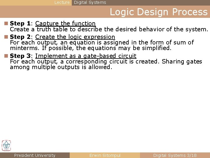
Lecture Digital Systems Logic Design Process n Step 1: Capture the function Create a truth table to describe the desired behavior of the system. n Step 2: Create the logic expression For each output, an equation is assigned in the form of sum of minterms. If possible, the equations may be simplified. n Step 3: Implement as a gate-based circuit For each output, a corresponding circuit is created. Sharing gates among multiple outputs is allowed. President University Erwin Sitompul Digital Systems 3/18
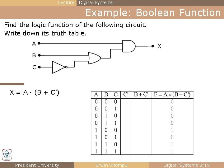
Lecture Digital Systems Example: Boolean Function Find the logic function of the following circuit. Write down its truth table. X = A · (B + C’) President University Erwin Sitompul Digital Systems 3/19
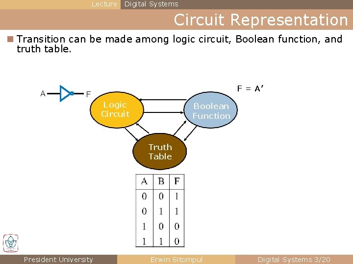
Lecture Digital Systems Circuit Representation n Transition can be made among logic circuit, Boolean function, and truth table. A F = A’ F Logic Circuit Boolean Function Truth Table President University Erwin Sitompul Digital Systems 3/20
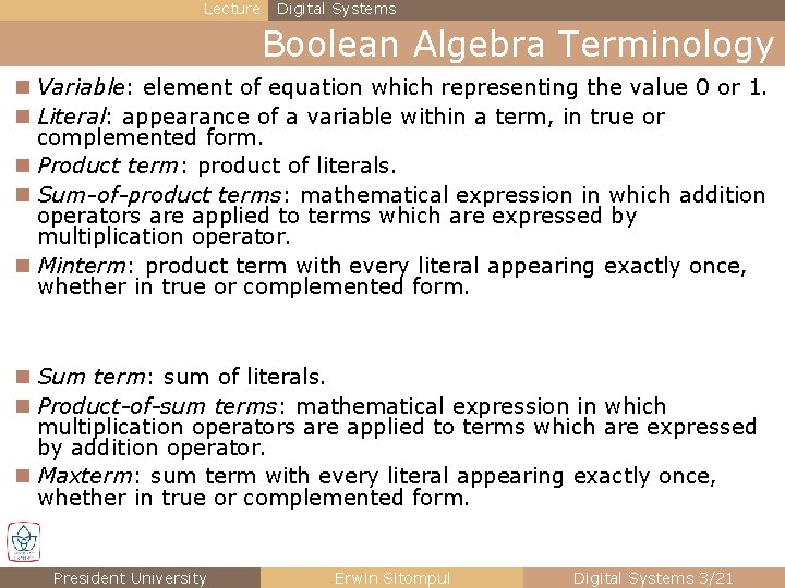
Lecture Digital Systems Boolean Algebra Terminology n Variable: element of equation which representing the value 0 or 1. n Literal: appearance of a variable within a term, in true or complemented form. n Product term: product of literals. n Sum-of-product terms: mathematical expression in which addition operators are applied to terms which are expressed by multiplication operator. n Minterm: product term with every literal appearing exactly once, whether in true or complemented form. n Sum term: sum of literals. n Product-of-sum terms: mathematical expression in which multiplication operators are applied to terms which are expressed by addition operator. n Maxterm: sum term with every literal appearing exactly once, whether in true or complemented form. President University Erwin Sitompul Digital Systems 3/21
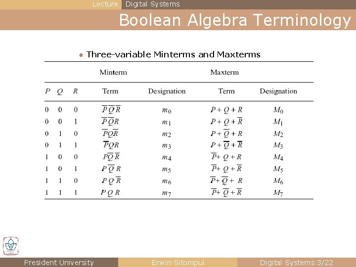
Lecture Digital Systems Boolean Algebra Terminology ● Three-variable Minterms and Maxterms President University Erwin Sitompul Digital Systems 3/22
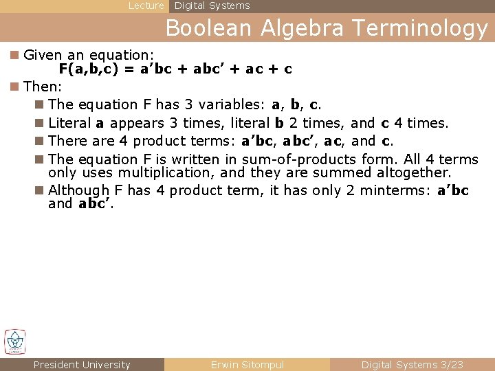
Lecture Digital Systems Boolean Algebra Terminology n Given an equation: F(a, b, c) = a’bc + abc’ + ac + c n Then: n The equation F has 3 variables: a, b, c. n Literal a appears 3 times, literal b 2 times, and c 4 times. n There are 4 product terms: a’bc, abc’, ac, and c. n The equation F is written in sum-of-products form. All 4 terms only uses multiplication, and they are summed altogether. n Although F has 4 product term, it has only 2 minterms: a’bc and abc’. President University Erwin Sitompul Digital Systems 3/23
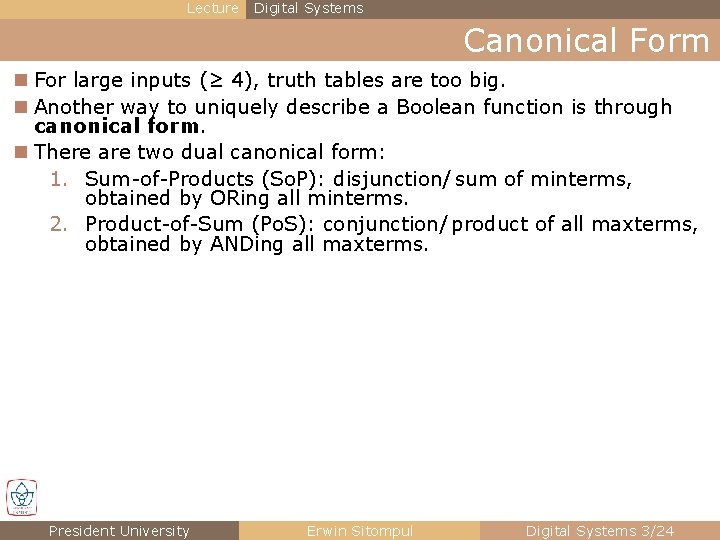
Lecture Digital Systems Canonical Form n For large inputs (≥ 4), truth tables are too big. n Another way to uniquely describe a Boolean function is through canonical form. n There are two dual canonical form: 1. Sum-of-Products (So. P): disjunction/ sum of minterms, obtained by ORing all minterms. 2. Product-of-Sum (Po. S): conjunction/ product of all maxterms, obtained by ANDing all maxterms. President University Erwin Sitompul Digital Systems 3/24
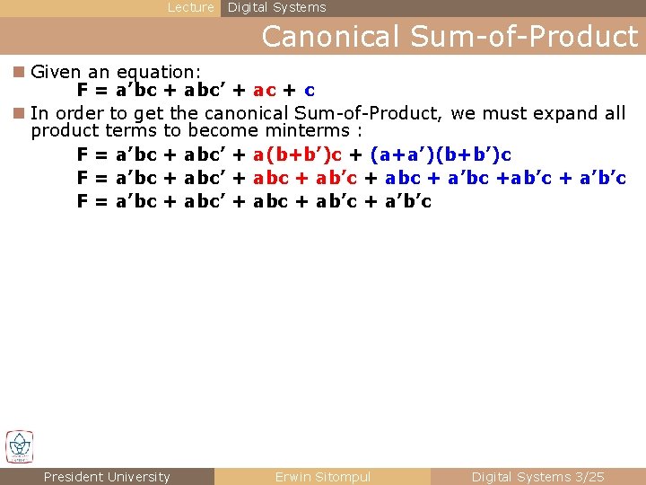
Lecture Digital Systems Canonical Sum-of-Product n Given an equation: F = a’bc + abc’ + ac + c n In order to get the canonical Sum-of-Product, we must expand all product terms to become minterms : F = a’bc + abc’ + a(b+b’)c + (a+a’)(b+b’)c F = a’bc + abc’ + abc + ab’c + abc + a’bc +ab’c + a’b’c F = a’bc + abc’ + abc + ab’c + a’b’c President University Erwin Sitompul Digital Systems 3/25
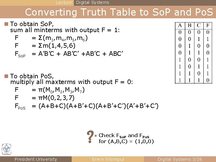
Lecture Digital Systems Converting Truth Table to So. P and Po. S n To obtain So. P, sum all minterms with output F = 1: F = Σ(m 1, m 4, m 5, m 6) F = Σm(1, 4, 5, 6) FSo. P = A’B’C + AB’C’ +AB’C + ABC’ n To obtain Po. S, multiply all maxterms with output F = 0: F = π(M 0, M 2, M 3, M 7) F = πM(0, 2, 3, 7) FPo. S = (A+B+C)(A+B’+C’)(A’+B’+C’) ? President University ● Check FSo. P and FPo. S for (A, B, C) = (1, 0, 0) Erwin Sitompul Digital Systems 3/26
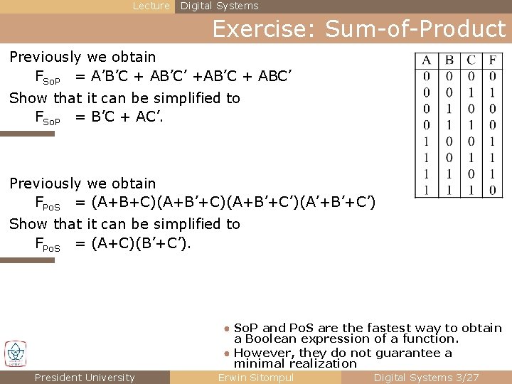
Lecture Digital Systems Exercise: Sum-of-Product Previously we obtain FSo. P = A’B’C + AB’C’ +AB’C + ABC’ Show that it can be simplified to FSo. P = B’C + AC’. Previously we obtain FPo. S = (A+B+C)(A+B’+C’)(A’+B’+C’) Show that it can be simplified to FPo. S = (A+C)(B’+C’). ● So. P and Po. S are the fastest way to obtain a Boolean expression of a function. ● However, they do not guarantee a minimal realization President University Erwin Sitompul Digital Systems 3/27
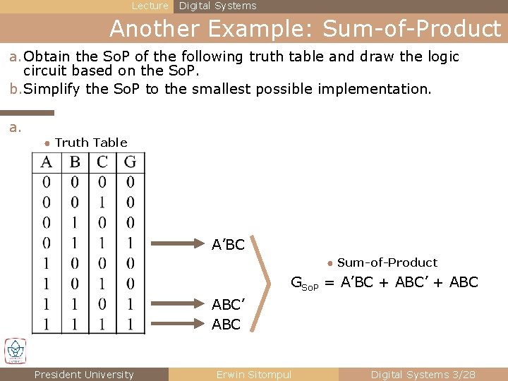
Lecture Digital Systems Another Example: Sum-of-Product a. Obtain the So. P of the following truth table and draw the logic circuit based on the So. P. b. Simplify the So. P to the smallest possible implementation. a. ● Truth Table A’BC ● Sum-of-Product GSo. P = A’BC + ABC’ ABC President University Erwin Sitompul Digital Systems 3/28
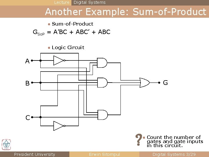
Lecture Digital Systems Another Example: Sum-of-Product ● Sum-of-Product GSo. P = A’BC + ABC’ + ABC ● Logic Circuit ? President University Erwin Sitompul ● Count the number of gates and gate inputs in this circuit. Digital Systems 3/29
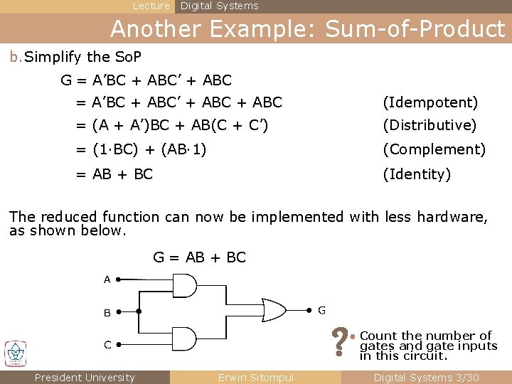
Lecture Digital Systems Another Example: Sum-of-Product b. Simplify the So. P G = A’BC + ABC’ + ABC (Idempotent) = (A + A’)BC + AB(C + C’) (Distributive) = (1·BC) + (AB· 1) (Complement) = AB + BC (Identity) The reduced function can now be implemented with less hardware, as shown below. G = AB + BC ? President University Erwin Sitompul ● Count the number of gates and gate inputs in this circuit. Digital Systems 3/30
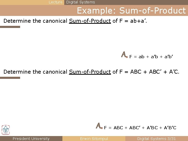
Lecture Digital Systems Example: Sum-of-Product Determine the canonical Sum-of-Product of F = ab+a’. A● F = ab + a’b’ Determine the canonical Sum-of-Product of F = ABC + ABC’ + A’C. A● F = ABC + ABC’ + A’BC + A’B’C President University Erwin Sitompul Digital Systems 3/31
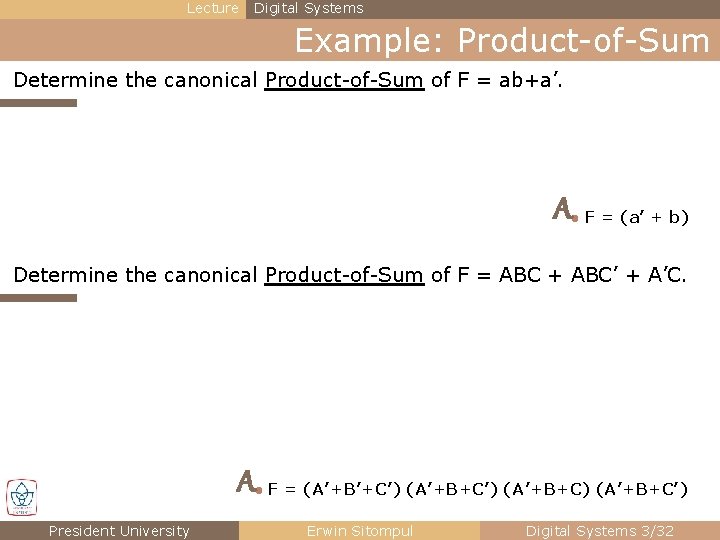
Lecture Digital Systems Example: Product-of-Sum Determine the canonical Product-of-Sum of F = ab+a’. A● F = (a’ + b) Determine the canonical Product-of-Sum of F = ABC + ABC’ + A’C. A● F = (A’+B’+C’) (A’+B+C) (A’+B+C’) President University Erwin Sitompul Digital Systems 3/32
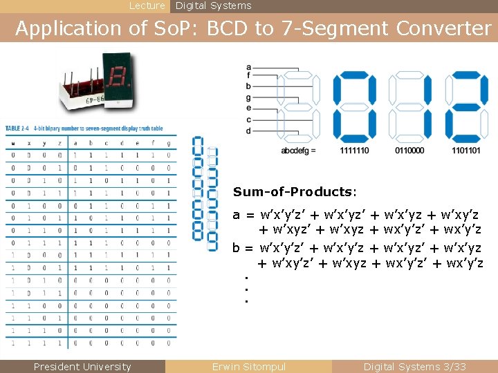
Lecture Digital Systems Application of So. P: BCD to 7 -Segment Converter Sum-of-Products: a = w’x’y’z’ + w’x’yz + w’xy’z + w’xyz’ + w’xyz + wx’y’z’ + wx’y’z b = w’x’y’z’ + w’x’y’z + w’x’yz’ + w’x’yz + w’xy’z’ + w’xyz + wx’y’z’ + wx’y’z . . . President University Erwin Sitompul Digital Systems 3/33
Lecture Digital Systems Example: Boolean Function Built a circuit that will produce the function G = A·B + A’·B·C’. Write down also its truth table. President University Erwin Sitompul Digital Systems 3/34
Lecture Digital Systems Homework 3 1. A house alarm (F) should sound if the alarm (A) is enabled and either the window is shaken (S) or the door is opened (D). Determine the Boolean equation F of this system. 2. An expansion project (P) will be conducted if it is approved by the manager (G). If the project is not approved by the manager, the project can still be conducted if it is approved by either construction supervisor (C) only or maintenance supervisor (M) only. Determine the Boolean equation P of this system. 3. a) Determine the canonical Sum-of-Products expression for the following function: F(A, B, C) = Σm(2, 3, 4, 6, 7). b) Find the canonical Product-of-Sums expression for F. 4. For the following logic equation Y = KL’ + L’M + KM a) Draw the complete logic diagram from the equation above. b) Give the truth table. c) Give the minterm and maxterm representation (Σm, πM). d) Give the equation for canonical Sum-of-Products and Product-of-Sums. n Deadline: Wednesday, 7 October 2015. President University Erwin Sitompul Digital Systems 3/35