Digital Logic Systems Combinational Circuits Basic Gates Truth

Digital Logic Systems Combinational Circuits

Basic Gates & Truth Tables

Basic Gates AND Gate OR Gate NOT Gate

More Gates NAND Gate NOR Gate BUF Gate

More Gates XOR Gate XNOR Gate

n-Input Gates 3 -Input XOR Gate 4 -Input OR Gate 5 -Input NOR Gate 5 -Input AND Gate

Definitions AND It gives a logical output true only if all the inputs are true OR It gives a logical output true if any of the inputs is true XOR It gives a logical output true only if an oddnumber of inputs is true NOT It gives a logical output true if the input is false and vice versa

Truth Table A truth table is a tabular procedure to express the relationship of the outputs to the inputs of a Logical System

Truth Tables for Gates a 0 0 1 1 b 0 1 f. AND 0 0 0 1 a 0 0 1 1 b 0 1 f. OR 0 1 1 1 AND Operation OR Operation AND Gate OR Gate a 0 1 f. NOT 1 0 NOT Operation NOT Gate

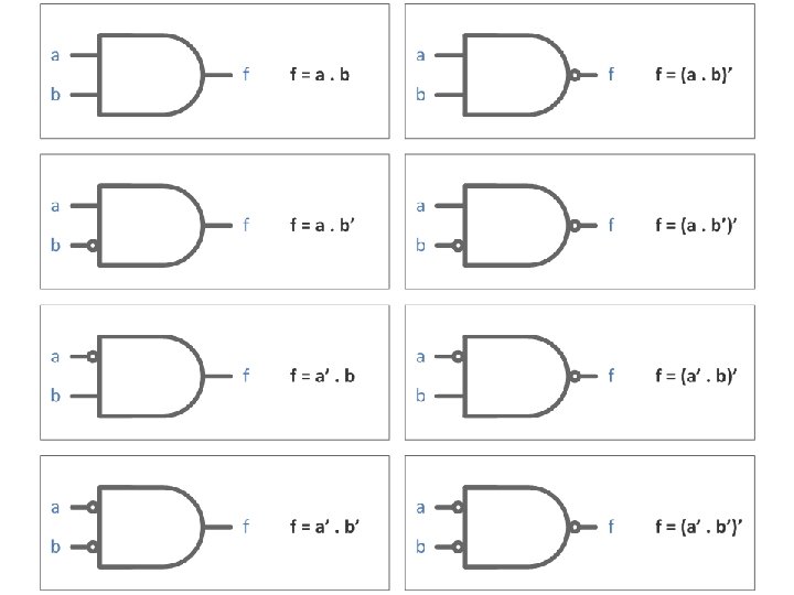
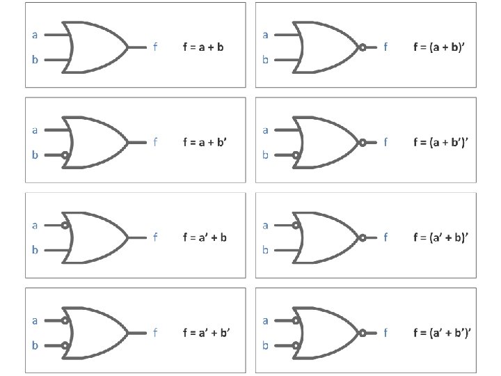
Truth Tables for Gates a 0 0 1 1 b f. NAND 0 1 1 1 0 a 0 0 1 1 b 0 1 f. NOR 1 0 0 0 NAND Operation NOR Operation NAND Gate NOR Gate a 0 1 f. BUF 0 1 BUF Operation BUF Gate

Truth Tables for Gates a 0 0 1 1 b 0 1 f. XOR 0 1 1 0 XOR Operation XOR Gate a 0 0 1 1 b f. XNOR 0 1 1 0 0 0 1 1 XNOR Operation XNOR Gate

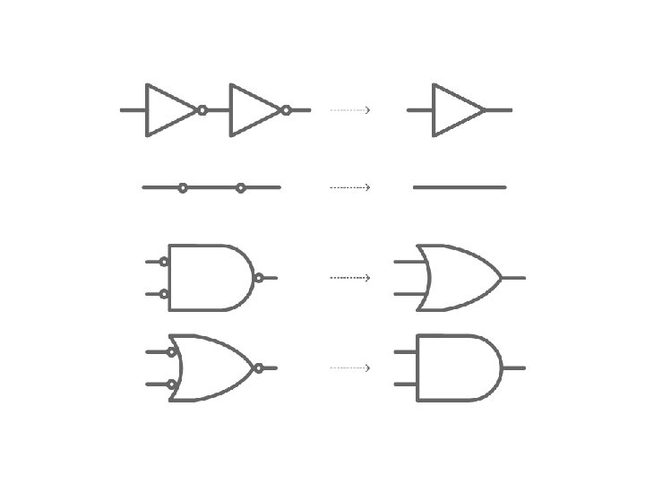
Bubbles A Bubble Implies a Logical Inversion Bubbles can be replaced by NOT Gates to get logically equivalent circuits

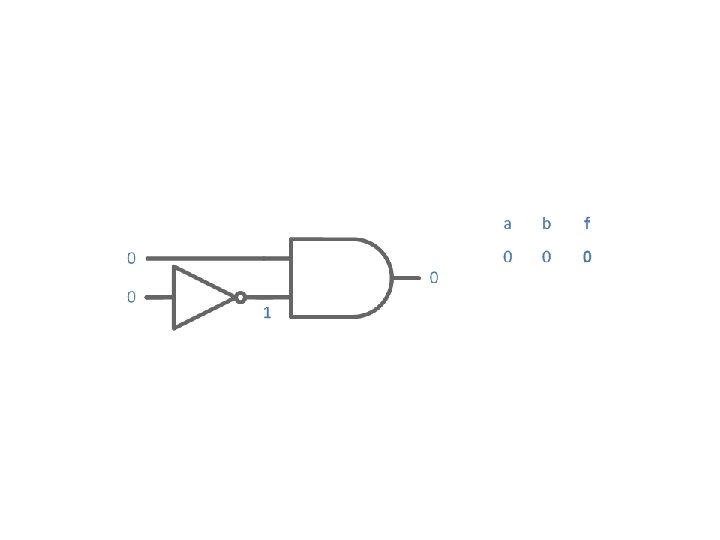
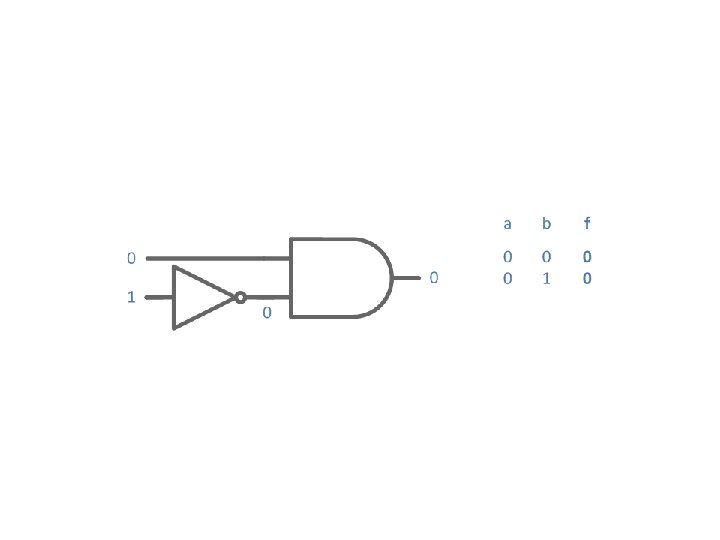
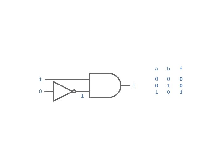
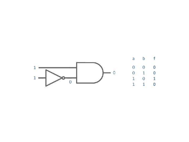
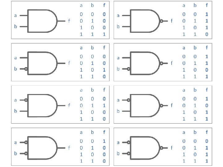
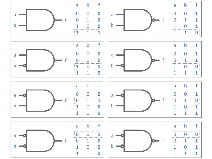
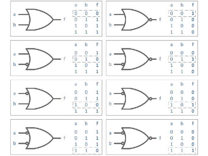

Generate tables for all combinations of bubbles and a XOR gate

Gate Equivalence = = =

Gate Equivalence = ? =

Gate Equivalence = =

Switching Expressions

Basic Switching Expressions AND f=a. b OR f=a+b NOT f = a’ f=ā

Is there an expression for XOR operation?

Switching Expressions

Switching Expressions
’")
Switching Expressions f 1 = a. b’ f 2 = (a + b)’

Switching Expressions

Switching Expressions

Switching Expressions f=?

Switching Expressions f=m+n m = a. b’ n = a’. b
 + (a’. b) This is the equivalent circuit")
Switching Expressions f = (a. b’) + (a’. b) This is the equivalent circuit and equivalent expression for a XOR operation

From Digital Design, 5 th Edition by M. Morris Mano and Michael Ciletti

Switching Expressions

Switching Expressions

Switching Expressions f 1 = a. b f 2 = a ^ b f 2 = (a. b’) + (a’. b)

Switching Expressions

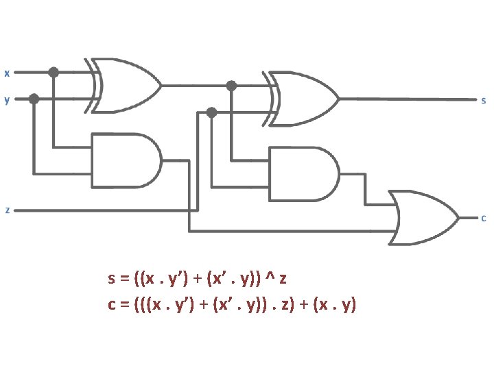
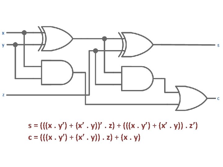
x 0 0 1 1 y 0 0 1 1 z 0 1 0 1 p=x^y g=x. y m=p. z s=p^z c=m+g

x 0 0 1 1 y 0 0 1 1 z 0 1 0 1 p=x^y g=x. y m=p. z s=p^z c=m+g 0 0 1 0 1 0 0 1

x 0 0 1 1 y 0 0 1 1 z 0 1 0 1 p=x^y g=x. y m=p. z s=p^z c=m+g 0 0 0 1 0 1 0 1 0

x 0 0 1 1 y 0 0 1 1 z 0 1 0 1 p=x^y g=x. y m=p. z s=p^z c=m+g 0 0 0 0 1 0 1 1 0 0 1 0 1 0 1 1

x 0 0 1 1 y 0 0 1 1 z 0 1 0 1 s 0 1 1 0 0 1 c 0 0 0 1 1 1

s=s c=m+g

s=p^z m=p. z g=g s=s c=m+g

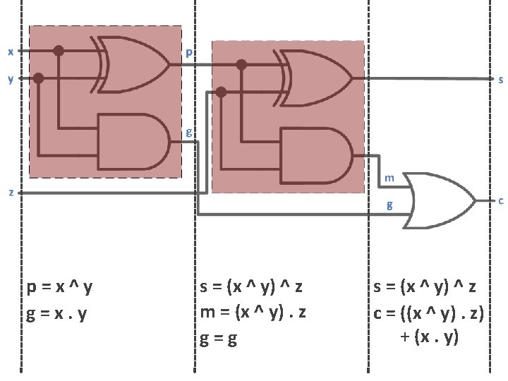
p=x^y g=x. y s=p^z m=p. z g=g s=s c=m+g
 ^ z m = (x ^")
p=x^y g=x. y s = (x ^ y) ^ z m = (x ^ y). z g=g s=s c=m+g
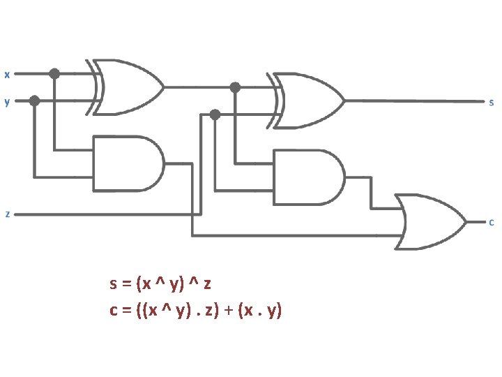

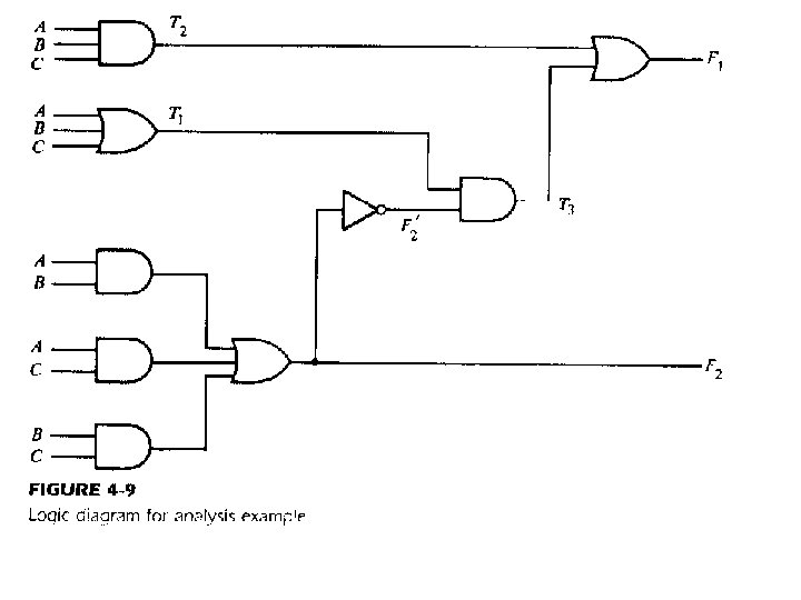
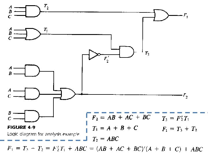
Procedure To obtain the output functions from a logic diagram, proceed as follows: 1. Label with arbitrary symbols all gate outputs that are a function of the input variables. Obtain the Boolean Functions for each gate. 2. Label with other arbitrary symbols those gates that are a function of input variables and/or preciously labeled gates. Find the Boolean functions of these gates. 3. Repeat the process in step 2 until all the outputs of the circuit are obtained. 4. By repeated substitution of previously defined functions, obtain the output Boolean functions in terms of input variables only.
- Slides: 59