Digital Logic Design Lecture 22 Announcements Homework 7


 • This")


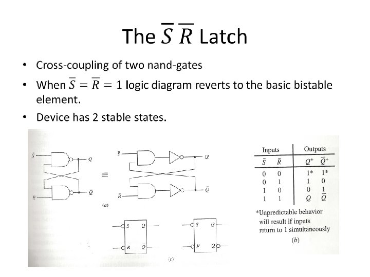
 Latch •")
 Latch •")


- Slides: 26
Digital Logic Design Lecture 22
Announcements • Homework 7 due today • Homework 8 on course webpage, due 11/20. • Recitation quiz on Monday on material from Lectures 21, 22
Agenda • Last time: – Programmable Logic Devices (5. 7 -5. 10) • This time: – New topic: Flip-flops • • • The Basic Bistable Element (6. 1) Latches (6. 2) Timing Considerations (6. 3) Master-Slave Flip-Flops (6. 4) Edge-Triggered Flip-Flops (6. 5)
Sequential Networks • The logic networks studied so far are combinational networks: – The outputs at any instant depend only upon the inputs present at that instant. • Sequential Network: – The outputs at any instant are dependent not only upon the inputs present at that instant but also upon the past history of inputs. • Sequential networks have memory. – The information preserved is referred to as the internal state, secondary state, or state of the network.
Sequential Networks • Synchronous sequential network – Behavior is determined by the values of the signals at only discrete instants of time. – Master-clock generator which produces a sequence of clock pulses that sample the input. • Asynchronous sequential network – Behavior of the network is immediately affected by the input signal changes.
Flip-Flop • The basic logic element that provides memory in many sequential networks. • Flip-flop itself is a simple sequential network. – All sequential networks require the existence of feedback. – Feedback is present in flip-flop circuits. • Flip-flop has two stable conditions. – Each of this is associated with a state or storage of a binary symbol.
The Basic Bistable Element •
The Basic Bistable Element •
The Basic Bistable Element • Has no inputs. • When power is applied, it becomes stable in one of its two stable states and remains in this state until power is removed. • To be useful, must be able to force the device into a particular state. • A flip-flop is a bistable device, with inputs, that remains in a given state as long as power is applied and until input signals are applied to cause its output to change. • Inputs to flip-flops: – Asynchronous or direct input: a signal change produces an immediate change in the state of the flip-flop. – Synchronous input: A signal change does not immediately affect the state of the flip-flop. Affects it only when some control signal (clock) occurs.
Latches • Latches are one class of flip-flops • The timing of the output changes is not controlled – The output responds immediately to changes on the input lines. – Input lines are continuously being interrogated. • Sections 6. 4, 6. 5: flip-flops in which the timing of the output changes is controlled.
The SR (set-reset) Latch •
The SR (set-reset) Latch •
Next state is the same as the previous state. The SR Latch
The Gated SR Latch •
• The Gated SR Latch
The Gated SR Latch
The Gated D Latch • The latches discussed thus far each has an input combination that is not recommended. • The gated D (data) latch does not have this problem. • Gated SR-latch in which a not-gate is connected between the S and R terminals. • Why does this help?
The Gated D Latch
Timing Considerations • Responses to inputs are not really immediate, but occur after some appropriate time delay. • To achieve desired responses, certain timing constraints must be satisfied.
Propagation Delays • In general, these may be different.
• Timing Diagram
Minimum Pulse Width •
Setup and Hold Times •
Unpredictable Response in a gated D latch