Digital Logic Design Dr Waseem Ikram Lecture No


- Slides: 24
Digital Logic & Design Dr. Waseem Ikram Lecture No. 36
Recap
D flip-flop input table for X=0 Present State Next State X=0 D flip-flop inputs Q 2 0 0 Q 1 0 0 Q 0 0 1 Q 2 0 0 Q 1 0 1 Q 0 1 0 D 2 0 0 D 1 0 1 D 0 1 0 0 0 1 1 1 0 0 1 1 0 1 0 0 1 1 0 1 0 0 1 1 0 1 0
D flip-flop input table for X=1 Present State Next State X=1 D flip-flop inputs Q 2 0 0 Q 1 0 0 Q 0 0 1 Q 2 1 0 Q 1 1 0 Q 0 1 0 D 2 1 0 D 1 1 0 D 0 1 0 0 0 1 1 1 0 0 1 1 0 1 0 0 1 1 0 1 0
Boolean expression for D 2 inputs Q 2 Q 1 / Q 0 0 1 1 0 0 X 00 0 1 0 0 0 1 11 1 0 10 1 1
Boolean expression for D 1 inputs Q 2 Q 1/Q 0 X 00 01 11 10 00 0 1 01 1 0 1 0 10 0 1
Boolean expression for D 0 inputs Q 2 Q 1/Q 0 X 00 01 11 10 00 1 1 0 0 01 1 1 0 0 10 1 1 0 0
3 -bit Up/Down Counter
Input/Output Pin Definition of 3 -bit Up/Down Counter Pin Definition CLOCK, CLEAR, X 3; Q 0, Q 1, Q 2 23 ISTYPE ‘reg, buffer’; pin 1, 2, pin 21, 22,
Equation Definition of 3 -bit Up/Down Counter Equations Q 0 : = !Q 0; Q 1 : = Q 0 $ Q 1 $ X; Q 2 : = !Q 2 & !Q 1 & !Q 0 & X # !Q 2 & Q 1 & Q 0 & !X # Q 2 & !Q 0 & !X # Q 2 & Q 1 & X # Q 2 & !Q 1 & Q 0; [Q 0, Q 1, Q 2]. CLK = clock; [Q 0, Q 1, Q 2]. AR = !clear;
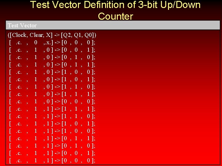
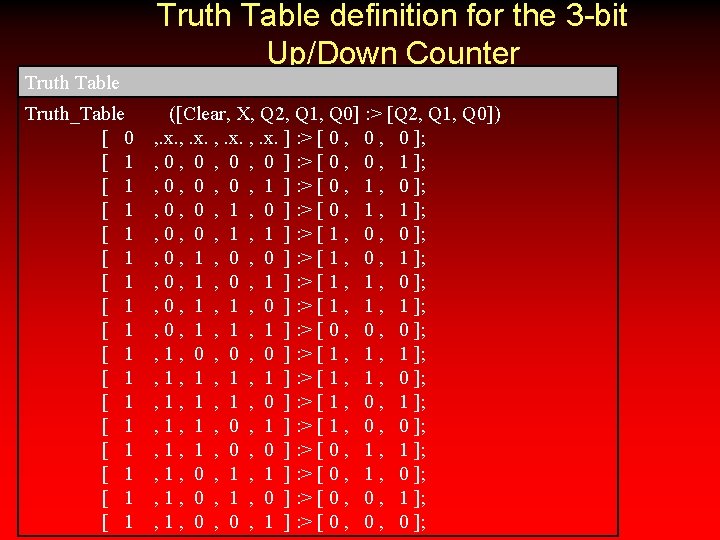
Equation Definition for Truth Table based Sequential Circuit definition Equations [Q 0, Q 1, Q 2]. CLK = clock; [Q 0, Q 1, Q 2]. AR = !clear;
State definition of the 3 -bit Up/Down Counter State Definition QSTATE A =[ B =[ C =[ D =[ E =[ F =[ G =[ H =[ 0, 0, 1, 1, = [Q 2, Q 1, Q 0]; 0 , 0 ]; 0 , 1 ]; 1 , 0 ]; 1 , 1 ];
Defining the next states using IF-THENELSE State Diagram State A: if X then H else B; State B: if X then A else C; State C: if X then B else D; State D: if X then C else E; State E: if X then D else F; State F: if X then E else G; State G: if X then F else H; State H: if X then G else A;
Defining the next states using GOTO State Diagram State A: State B: State C: State D: State E: State F: State G: State H: GOTO B; GOTO C; GOTO D; GOTO E; GOTO F; GOTO G; GOTO H; GOTO A;
State Diagram of Elevator
State table for Elevator Control for REQ 1, FLOOR 1 and OPEN inputs Presen Next State Sta te Next State REQ 1=1 FLOOR 1= 0 FLOOR 1= 1 OPEN= 0 OPEN= 1 W 1(00 x 0) x x x C 1(10 0) C 1 W 1 x x C 1 W 1 UP(11 0) x x x W 2(00 C 2 1) DO C 2 DO x x C 2(10 1) DO C 2 DO x x x x REQ 1= 0 C 2 DO(11 x 1)
State table for Elevator Control for REQ 2, FLOOR 2 and OPEN inputs Present Next State te Next State REQ 2=0 REQ 2=1 FLOOR 2=0 FLOOR 2=1 OPEN=0 OPEN=1 C 1 UP x x C 1(100 C 1 ) UP C 1 UP x x UP(11 0) x x x W 2(00 1) x x x C 2(101 C 2 ) W 2 x x C 2 W 2 DO(11 1) x x x W 1(00 0) x
Block diagram of the Elevator State Machine
Programmable Sequential Logic
Truth-Table & State Diagram
Elevator Controller
Digital Logic Design Lecture 36