
DIGITAL IMAGING DIGITAL IMAGING TERMINOLOGY Film digitizer Digital

- Slides: 32
DIGITAL IMAGING
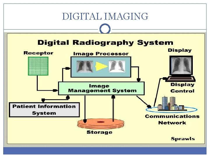
DIGITAL IMAGING
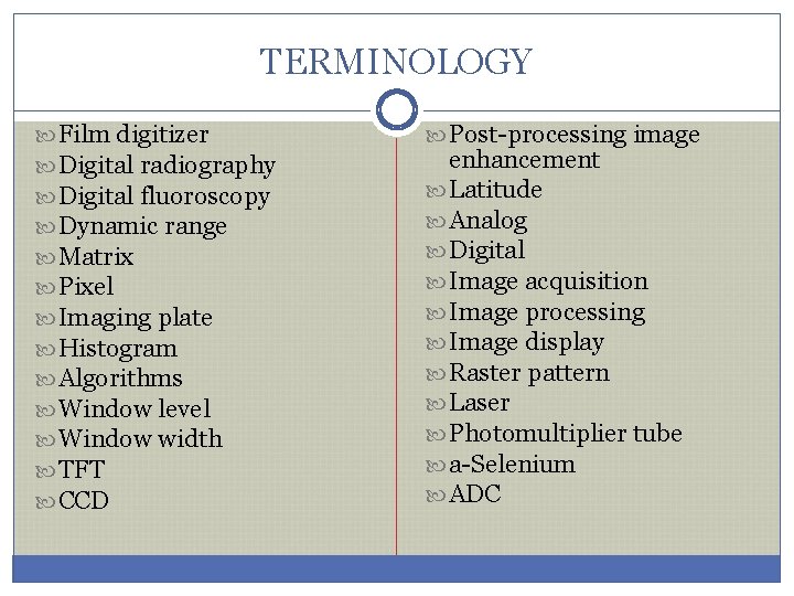
TERMINOLOGY Film digitizer Digital radiography Digital fluoroscopy Dynamic range Matrix Pixel Imaging plate Histogram Algorithms Window level Window width TFT CCD Post-processing image enhancement Latitude Analog Digital Image acquisition Image processing Image display Raster pattern Laser Photomultiplier tube a-Selenium ADC
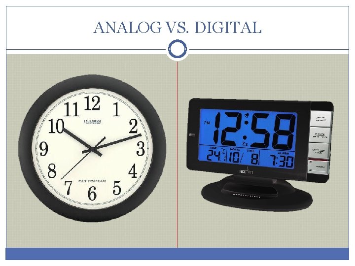
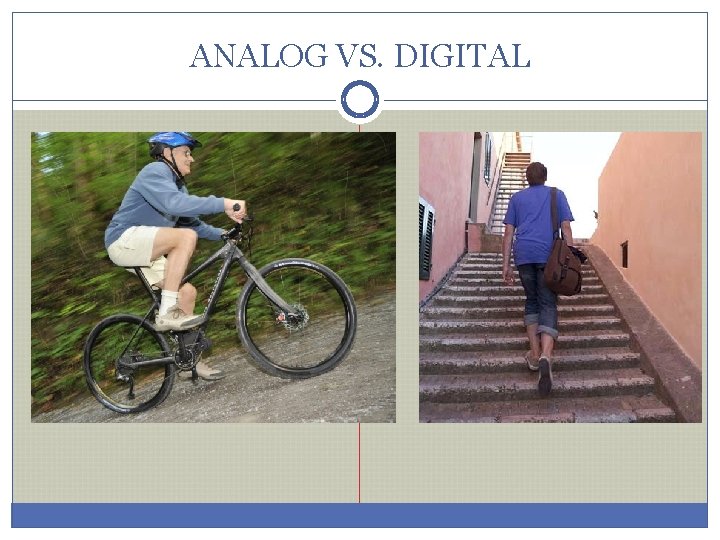
ANALOG VS. DIGITAL
ANALOG VS. DIGITAL
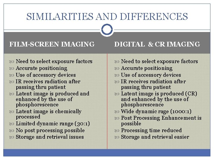
SIMILARITIES AND DIFFERENCES FILM-SCREEN IMAGING DIGITAL & CR IMAGING Need to select exposure factors Accurate positioning Use of accessory devices IR receives radiation after passing thru patient Latent image is produced and enhanced by the use of phosphorescence Latent image is chemically processed Limited dynamic range (30: 1) No post processing possible Storage and retrieval issues passing thru patient Latent image is produced (CR) and enhanced by the use of phosphorescence Wide dynamic rage (1000: 1) Post Processing Enhancement is possible Processing time reduced Storage and retrieval easier
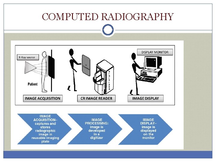
COMPUTED RADIOGRAPHY
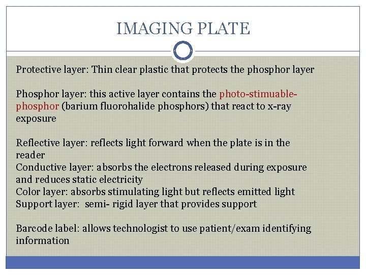
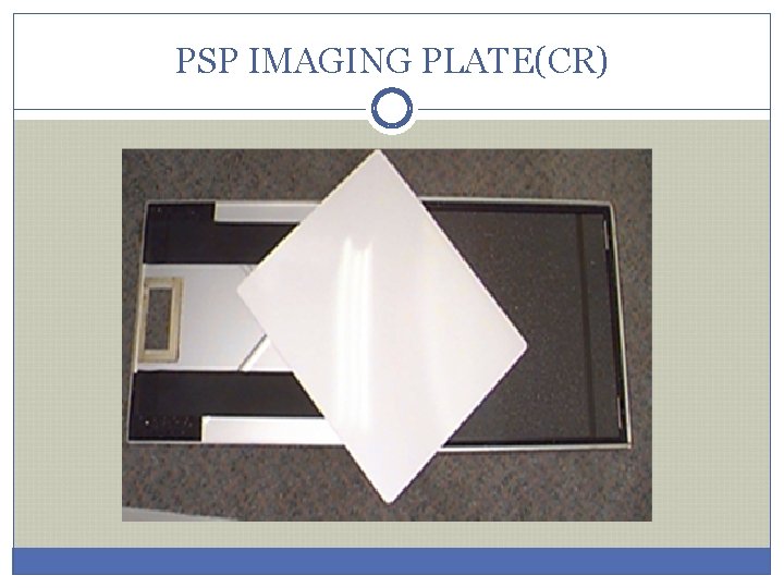
IMAGING PLATE Protective layer: layer Thin clear plastic that protects the phosphor layer Phosphor layer: layer this active layer contains the photo-stimuablephosphor (barium fluorohalide phosphors) that react to x-ray exposure Reflective layer: layer reflects light forward when the plate is in the reader Conductive layer: layer absorbs the electrons released during exposure and reduces static electricity Color layer: layer absorbs stimulating light but reflects emitted light Support layer: semi- rigid layer that provides support Barcode label: label allows technologist to use patient/exam identifying information
PSP IMAGING PLATE(CR)
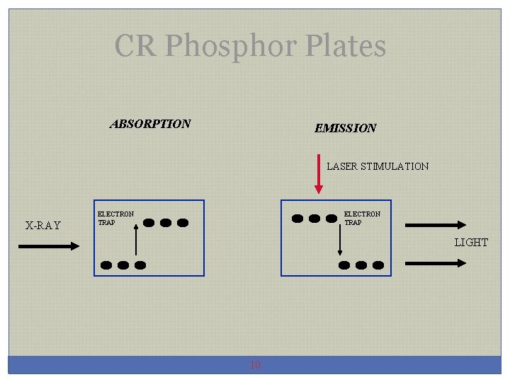
CR Phosphor Plates ABSORPTION EMISSION LASER STIMULATION X-RAY ELECTRON TRAP LIGHT 10
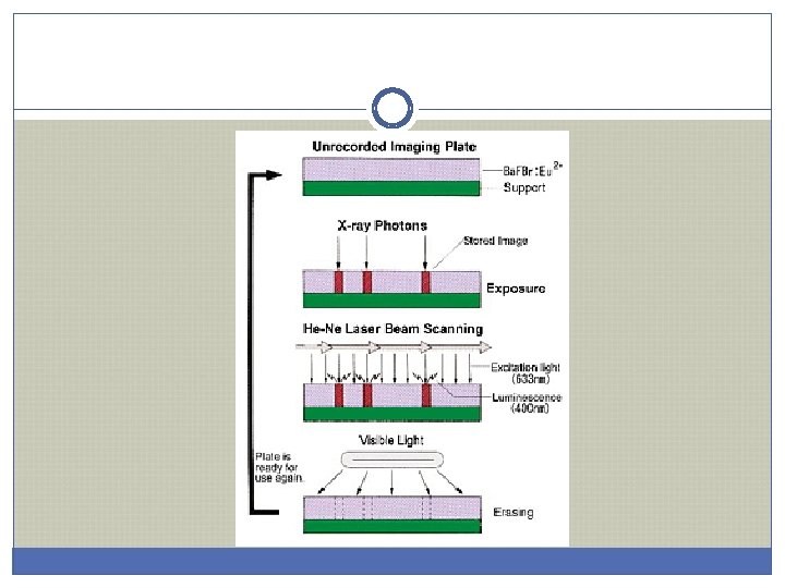
LATENT IMAGE (CR) v. Formed by x-ray interaction with PSP v. Ionizes phosphors, releasing electrons v. Electrons trapped in crystal lattice of phosphor v. Latent image is formed v. Remains until processed by a reader v. But does begin to decay so must be “read” in a timely fashion
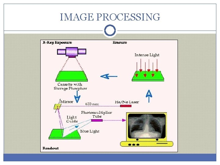
IMAGE PROCESSING
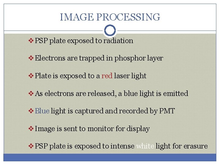
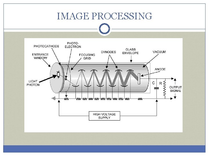
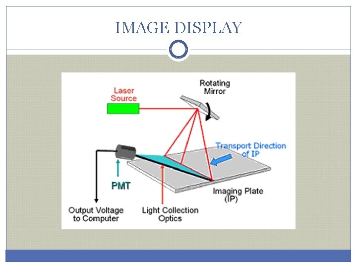
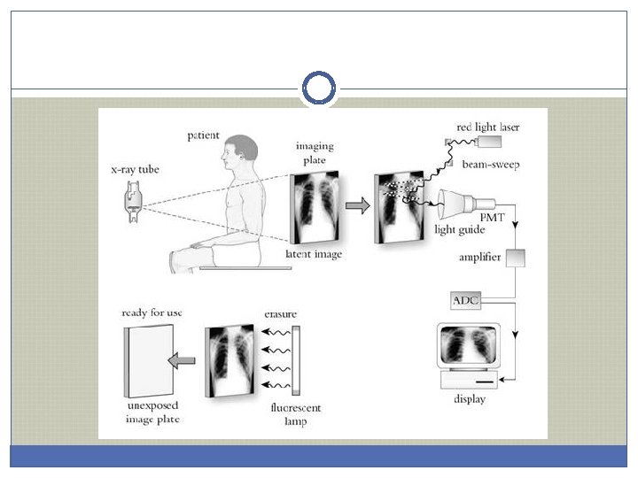
IMAGE PROCESSING v. PSP plate exposed to radiation v. Electrons are trapped in phosphor layer v. Plate is exposed to a red laser light v. As electrons are released, a blue light is emitted v. Blue light is captured and recorded by PMT v. Image is sent to monitor for display v. PSP plate is exposed to intense white light for erasure
IMAGE PROCESSING
IMAGE DISPLAY
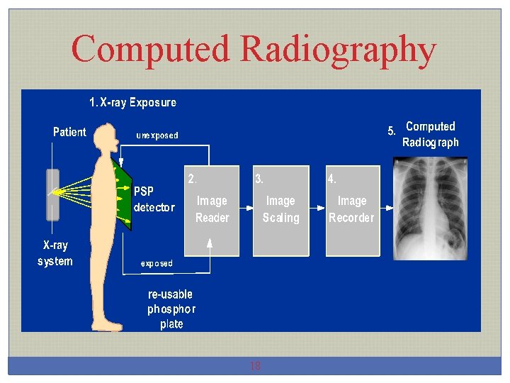
Computed Radiography 18
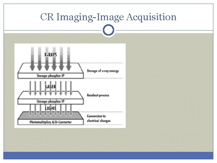
CR Imaging-Image Acquisition
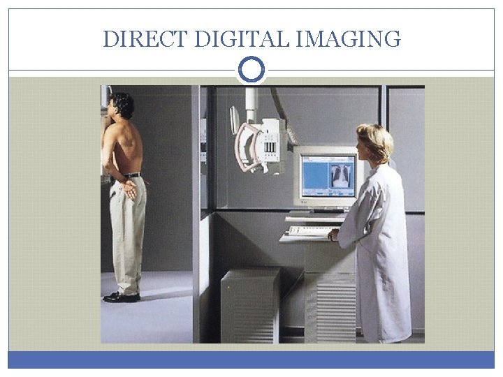
DIRECT DIGITAL IMAGING
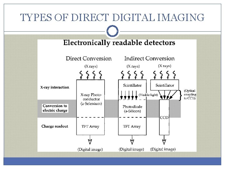
TYPES OF DIRECT DIGITAL IMAGING
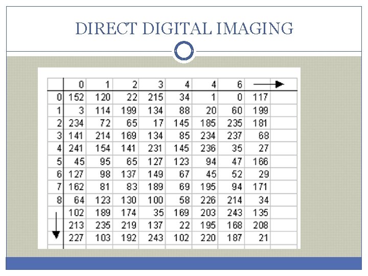
DIRECT DIGITAL IMAGING
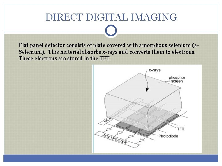
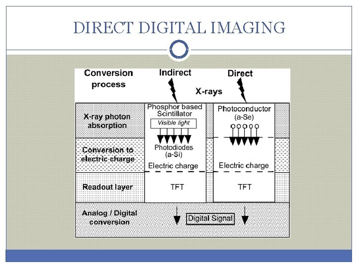
DIRECT DIGITAL IMAGING Flat panel detector consists of plate covered with amorphous selenium (a. Selenium). This material absorbs x-rays and converts them to electrons. These electrons are stored in the TFT
DIRECT DIGITAL IMAGING
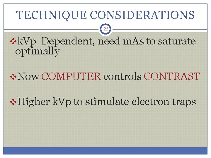
TECHNIQUE CONSIDERATIONS 25 vk. Vp Dependent, need m. As to saturate optimally v. Now COMPUTER controls CONTRAST v. Higher k. Vp to stimulate electron traps
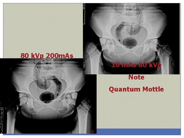
80 k. Vp 200 m. As 10 m. As 80 k. Vp Note Quantum Mottle 26
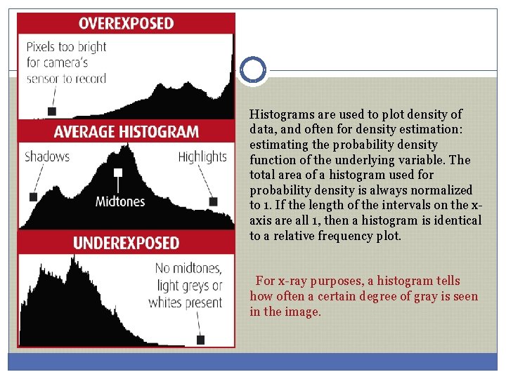
Histograms are used to plot density of data, and often for density estimation: estimating the probability density function of the underlying variable. The total area of a histogram used for probability density is always normalized to 1. If the length of the intervals on the xaxis are all 1, then a histogram is identical to a relative frequency plot. For x-ray purposes, a histogram tells how often a certain degree of gray is seen in the image.
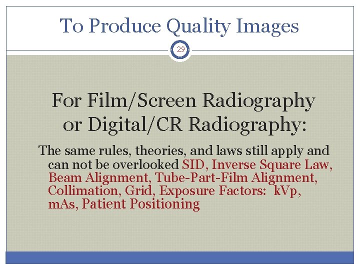
To Produce Quality Images 29 For Film/Screen Radiography or Digital/CR Radiography: The same rules, theories, and laws still apply and can not be overlooked SID, Inverse Square Law, Beam Alignment, Tube-Part-Film Alignment, Collimation, Grid, Exposure Factors: k. Vp, m. As, Patient Positioning
Quality Images 30 • Accounts for 85% of the total number of repeat exposures. • Has a direct affect on exposure technique.
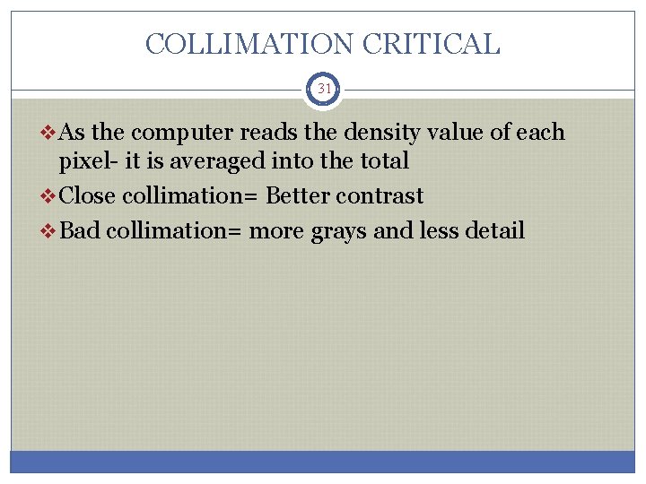
COLLIMATION CRITICAL 31 v. As the computer reads the density value of each pixel- it is averaged into the total v. Close collimation= Better contrast v. Bad collimation= more grays and less detail
NEXT WEEK……….