DIGITAL FILTER DESIGN A digital filter is in

 as symmetric around taking N as")
 Compute N: we discuss how to find N: usually, N gives filter roll")

, then")
 having 3 d.")
= c/ =0. 15. h(n)=hd(n) w(n) And h(7)=hd(7)= 0. 15 since w(7)=1. Due to")
 having:")
![for 18 n 0, n≠ 9 And hd(9)= [ -(14/15) +( /75)]/ =0. 08](https://slidetodoc.com/presentation_image_h2/695e00c4e79a515f3536034dc7cb0022/image-11.jpg "for 18 n 0, n≠ 9 And hd(9)= [ -(14/15) +( /75)]/ =0. 08")
- Slides: 11
DIGITAL FILTER DESIGN A digital filter is in fact • a linear causal DSP system with • impulse response h(n) • frequency response Where the shape of |H( )| gives the type of the filter (lowpass, highpass, …. . )(amplitude characteristics), and ( ) gives its phase characteristics FIR Digital Filter Design: FIR filters are always stable having no feedback and with linear phase characteristics This linear phase of the FIR filter is always preferred to avoid phase distortion at the output signal y(n). , i. e. ( ) = -k (k is a constant and the –sign indicates the phase lagging of the filter). is called a digital frequency (in rad) since it is normalized to the sampling frequency fs of the A/D converter, i. e. : = 2 f/fs where f is the actual analogue frequency( in Hz) of the continuous signal x(t).
Design procedure: we discuss how to find h(n) as symmetric around taking N as an odd number
1) Compute N: we discuss how to find N: usually, N gives filter roll of ( how fast is the transition from passband to stopband or how is the obtained response is closed to ideal response). In general: where k 1 and k 2 are gain values at 1 and 2 and k 1 is the -3 d. B level and k 2 is usually taken as the maximum SLL 2) Now to find the overall impulse response h(n) with windowing , then: h(n) = hd(n) where hd(n) depends on filter type (LFP, HPF, BSF. . ) and w(n) is usually chosen according to the required sidelobe level (SLL)at stopband
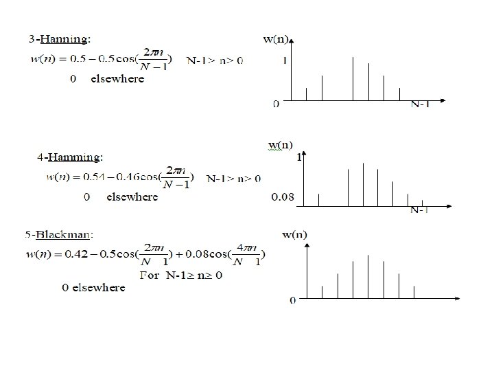
Several types of windows are used, but the most commonly used are listed below:
To find hd(n), then
Ex: Design and realize a linear phase digital lowpass filter (LPF) having 3 d. B cutoff frequency of 7. 5 KHz. and stopband attenuation of at least 40 d. B at 35 KHz. Find the difference equation and the frequency response of this filter. Use fs = 100 KHz. k 2= -40 d. B, this gives maxi SLL Hanning window is chosen since its max. SLL is -44 d. B, then k=4 Next, we find N: =2 f/fs If f 1=7. 5 KHz, then 1=2 (7. 5)/100=0. 15 rad f 2=35 KHz, then 2=2 (35)/100=0. 7 rad Next we find the midpoint =(N-1)/2=(15 -1)/2=7 c= 1=0. 15 rad ( -3 d. B point). n≠ 7
hd(7)= c/ =0. 15. h(n)=hd(n) w(n) And h(7)=hd(7)= 0. 15 since w(7)=1. Due to symmetry around n=7, only h(n) values at n=0, 1, 2, 3, 4, 5, 6 need to be calculated
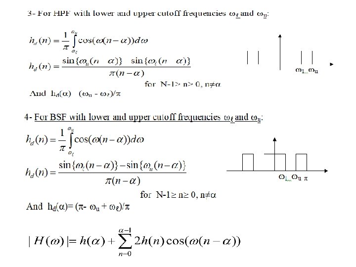
Example: Find the impulse response of a digital linear phase bandstop filter (BSF) having: 1 - 3 d. B cutoff at 20 Hz 1400 Hz. 2 - stopband attenuation of at least 40 d. B at 660 Hz and the difference equation as: 750 Hz. Use fs=3 KHz. y(n)=x(n) h(0)+x(n-1) h(1)+x(n-2) h(n-2)+…………+x(n-14) h(14) Solution: since linear phase, then this is FIR filter. the frequency response: ( ) = -7 rad For 40 d. B SLL, we use Hanning window H. W: Repeat previous example for a HPF with 3 d. B cutoff at 0. 7 rad and stopband attenuation of at least 50 d. B at 0. 2 rad. N=max(N 1, N 2)=max(19, 19)=19. This gives =9. The u and ℓ are the 3 d. B cutoff of the highpass and lowpass sections respectively, u=2 (1400)/3000=(14/15) rad And ℓ= 2 (20)/3000= /75 rad
for 18 n 0, n≠ 9 And hd(9)= [ -(14/15) +( /75)]/ =0. 08