DIGITAL EQUIPMENT MAY 2008 TERMINOLOGY REVIEW ARRT CONTENT


 - work list")


 •")
-Selenium Computed Radiography (CR) - PSL")
 • flat panel detectors – (direct")


")


 is a reference histogram. • LUT is")


 - work list")


 • flat panel detectors – (direct")


 is equal to")


- Slides: 126
DIGITAL EQUIPMENT MAY 2008
TERMINOLOGY REVIEW ARRT CONTENT SPECS 2008
ARRT SPECS - DIGITAL • Image Receptors • digital image characteristics – – – spatial resolution sampling frequency DEL (detector element size) receptor size and matrix size image signal (exposure related) – quantum mottle – SNR (signal to noise ratio) or – CNR (contrast to noise ratio) • Digital Systems • electronic collimation • grayscale rendition or look-up table (LUT) • edge enhancement/ – noise suppression • contrast enhancement • system malfunctions (e. g. , ghost image, banding, erasure, dead pixels, readout problems, printer distortion)
ARRT SPECS - DIGITAL • Image Display – – – viewing conditions (i. e. , luminance, ambient lighting spatial resolution contrast resolution/dynamic range DICOM gray scale function window level and width function • Image Acquisition and Readout • PSP (photo-stimulable phosphor) • flat panel detectors – (direct and indirect) • • • Noise Acceptable Range of Exposure Indicator Determination Gross Exposure Error Image Degradation (mottle, light or dark, low contrast)
ARRT SPECS - DIGITAL • Recognition of Malfunctions • Digital Image Receptor Systems • Digital artifacts – (grid lines, Moiré effect or aliasing) – maintenance (e. g. , detector fog) – ( non-uniformity, erasure)
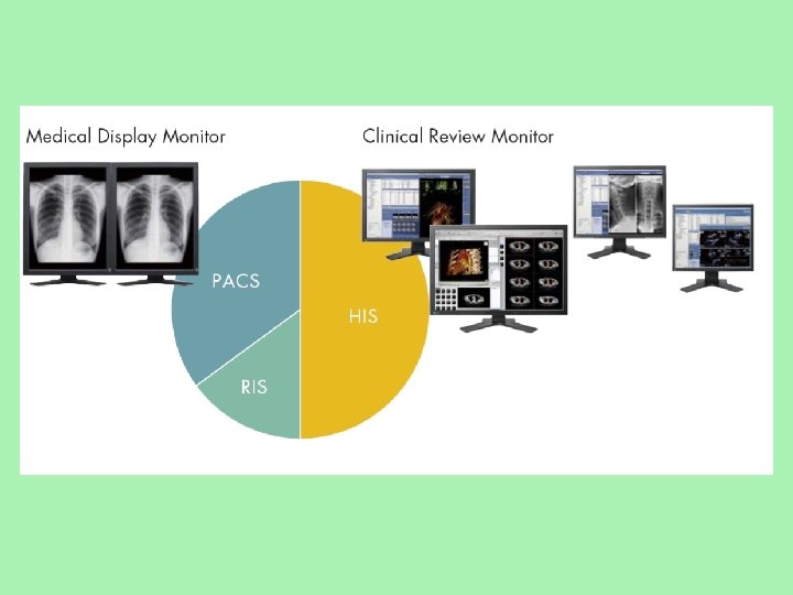
ARRT SPECS - DIGITAL • PACS • HIS (hospital information system) - work list • RIS (radiology information system) • DICOM • Workflow (inappropriate documentation, lost images, mismatched images, corrupt data) • windowing and leveling
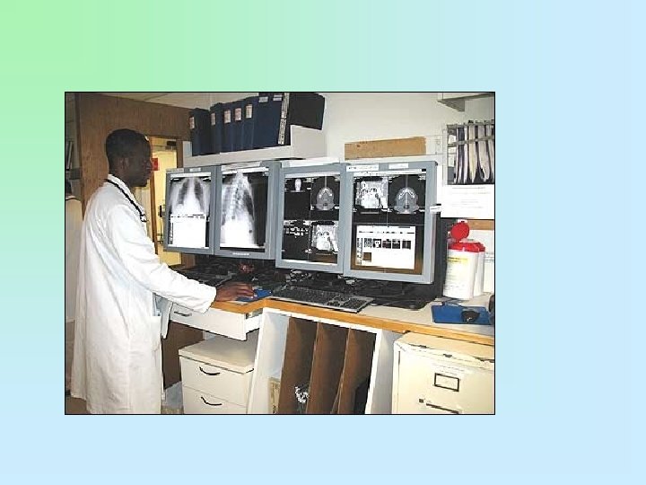
Review of Digital Radiography and PACS
Key Terms • Computed radiography • DICOM (digital imaging and communications in medicine) • Digital imaging • Digital radiography • Direct capture DR • Indirect capture DR • PACS • Teleradiology
Digital Radiography Direct Capture Indirect Capture Direct-to-Digital Radiography (DDR)-Selenium Computed Radiography (CR) - PSL Direct-to-Digital Radiography Silicon Scint. Laser Scanning Digitizers
Image Acquisition and Readout • PSP (photo-stimulable phosphor) • flat panel detectors – (direct and indirect)
Computed Radiography • • Uses storage phosphor plates Uses existing equipment Requires special cassettes Requires a special cassette reader • Uses a computer workstation and viewing station and a printer
Computed Radiography • Storage phosphor plates are similar to intensifying screens. • Imaging plate stores x-ray energy for an extended time. • Process was first introduced in the United States by Fuji Medical Systems of Japan in 1983. • First system used a phosphor storage plate, a reader, and a laser printer.
Imaging Plate • Construction • Image recorded on a thin sheet of plastic known as the imaging plate • Consists of several layers:
Cassette and Imaging Plate • Cassette contains a window with a barcode label or barcode sticker on the cassette. • Label enables technologist to match the image information with the patient-identifying barcode on the exam request.
Using the Laser to Read the Imaging Plate • The light collection optics direct the released phosphor energy to an optical filter and then to the photodetector. • Although there will be variances between manufacturers, the typical throughput is 50 cassettes per hour. • Some manufacturers claim up to 150 cassettes per hour, but based on average
• • • Process up to 101 cassettes an hour. • Handle 16 cassettes at one time: up to 8 queued for processing, and 8 erased and ready for new imaging studies. • Cassette is ready to reuse in 40 seconds. * • Review an image in 34 seconds at a Kodak Direct. View remote operations panel. * • “Drop-and go” workflow virtually
• Based on proven Direct. View CR 850 system design • ·Process up to 62 35 x 43 cm plates an hour • ·Small footprint size of 25 x 29 inch (63. 5 x 73. 6 cm
Digital Radiography • Cassetteless system • Uses a flat panel detector or charge-coupled device (CCD) hard-wired to computer • Requires new installation of room or retrofit
Digital Radiography • DR is hard-wired. • DR is cassetteless. • Detectors are permanently enclosed inside a rigid protective housing. • Thin-film transistor (TFT) detector arrays may be used in direct- and indirect-conversion detectors.
Digital Radiography • Two types of digital radiography • Indirect capture DR • Machine absorbs x-rays and converts them to light. • CCD or thin-film transistor (TFT) converts light to electric signals. • Computer processes electric signals. • Images are viewed on computer monitor.
Digital Radiography • Direct capture DR • Photoconductor absorbs x-rays. • TFT collects signal. • Electrical signal is sent to computer for processing. • Image is viewed on computer screen.
Digital Radiography • DR used CCD technology developed by the military and then used TFT arrays shortly after. • CCD and TFT technology developed and continues to develop in parallel. • No one technology has proved to be better than the other.
Flat-Panel Detectors • Consist of a photoconductor • Amorphous selenium • Holds a charge on its surface that can then be read out by a TFT
Direct Conversion • X-ray photons are absorbed by the coating material. • Photons are immediately converted into an electrical signal. • The DR plate has a radiation-conversion material or scintillator.
Direct Conversion DR Scintillator • Typically made of amorphous selenium • Absorbs x-rays and converts them to visible photons • Converts photons to electrical charges • Charges stored in the TFT detectors
Indirect Conversion • Similar to direct detectors in that the TFT technology is also used • Two-step process: • X-ray photons are converted to light. • Light photons are converted to an electrical signal. • A scintillator converts x-rays into visible light. • Light is then converted into an electrical charge by photodetectors such as amorphous silicon photodiode arrays or charge-coupled devices, or CCDs.
Indirect Conversion • More than a million pixels can be read and converted to a composite digital image in under a second.
Comparison of Film to CR and DR • For conventional x-ray film and computed radiography (CR), a traditional x-ray room with a table and wall Bucky is required. • For DR, a detector replaces the Bucky apparatus in the table and wall stand. • Conventional and CR efficiency ratings are about the same. • DR is much more efficient, and image is available immediately.
Comparison of Film to CR and DR • CR • A storage phosphor plate is placed inside of CR cassette. • Most storage phosphor plates are made of a barium fluorohalide. • When x-rays strike the photosensitive phosphor, some light is given off. • Some of the photon energy is deposited within the phosphor particles to create the latent image. • The phosphor plate is then fed through the CR reader.
Comparison of CR and DR • CR, continued • Focused laser light is scanned over the plate, causing the electrons to return to their original state, emitting light in the process. • This light is picked up by a photomultiplier tube and converted into an electrical signal. • The electrical signal is then sent through an analog-to -digital converter to produce a digital image that can then be sent to the technologist review station.
Comparison of CR & DR • No cassettes are required. • The image acquisition device is built into the table and/or wall stand or is enclosed in a portable device. • Two distinct image acquisition methods are indirect capture and direct capture. • Indirect capture is similar to CR in that the x-ray energy stimulates a scintillator, which gives off light that is detected and turned into an electrical signal. • With direct capture, the x-ray energy is detected by a photoconductor that converts it directly to a digital electrical signal.
Amorphous Silicon Detector • The light photons are then converted into an electric charge by the photodiode arrays. • Unlike the selenium-based system used for direct conversion, this type of indirectconversion detector technology requires a twostep process for x-ray detection. • The scintillator converts the x-ray beams into visible light, and light is then converted into an electrical charge by photodetectors, such as amorphous silicon photodiodes
Cesium Iodide Detectors • A newer type of amorphous silicon detector uses a cesium iodide scintillator. • The scintillator is made by growing very thin crystalline needles (5 µm wide) that work as light-directing tubes, much like fiber optics. • This allows greater detection of x-rays, and because there is almost no light spread, there is much greater resolution.
Cesium Iodide Detectors • These needles absorb the x-ray photons and convert their energy into light, channeling it to the amorphous silicon photodiode array. • As the light hits the array, the charge on each of the photodiodes decreases in proportion to the light received.
Charge-Coupled Devices • The oldest indirect-conversion DR system is based on CCDs. • X-ray photons interact with a scintillation material, such as photostimulable phosphors, and this signal is coupled or linked by lenses or fiber optics, which act like cameras.
Charge-Coupled Devices • These cameras reduce the size of the projected visible light image and transfer the image to one or more small (2 to 4 cm 2) CCDs, which convert the light into an electrical charge. • This charge is stored in a sequential pattern and released line by line and sent to an analog-todigital converter.
Charge-Coupled Devices • Even though CCD-based detectors require optical coupling and image size reduction, they are widely available and relatively low in cost.
Summary • There are two types of cassetteless digital imaging systems: direct and indirect. • Direct sensors are TFT arrays of amorphous silicon coated with amorphous selenium. • Direct sensors absorb x-ray photons and immediately convert them to an electrical signal.
Summary • Indirect-conversion detectors use a scintillator that converts x-rays into visible light, which is then converted into an electrical charge. • CCDs act as miniature cameras that convert light produced by x-ray interaction with photostimulable phosphors into an electrical charge.
Image Display – viewing conditions (i. e. , luminance, ambient lighting – DICOM gray scale function – window level and width function – spatial resolution – contrast resolution/dynamic range
MONITOR RESOLUTION DICOM gray scale function window level and width function
• Depending on modalities such as CT, CR, MRI, resolution requirements can range • from 1. 3 megapixels to 5 megapixels. • Generally, 3 megapixel and higher class displays are used for softcopy interpretation. • Where higher accuracy and a subtle reproduction of grayscale are critical in applications such as • mammography imaging, 5 megapixel resolution is required.
viewing conditions luminance, ambient lighting
DICOM gray scale function window level and width function • A photometer to a monitor screen in a check of the monitor's conformance with the DICOM Grayscale Standard Display Function.
DICOM gray scale function window level and width function
Grayscale or color monitors Digital Systems electronic collimation grayscale rendition or look-up table (LUT) edge enhancement/ noise suppression contrast enhancement
Detective Quantum Efficiency • How efficiently a system converts the x-ray input signal into a useful output image is known as detective quantum efficiency, or DQE. • DQE is a measurement of the percentage of xrays that are absorbed when they hit the detector.
Detective Quantum Efficiency • In other words, CR records all of the phosphor output. Systems with higher quantum efficiency can produce higher-quality images at a lower dose. • Indirect and direct DR capture technology has increased DQE over CR. • However, DR direct capture technology, because it does not have the light conversion step and consequently no light spread, increases DQE the most.
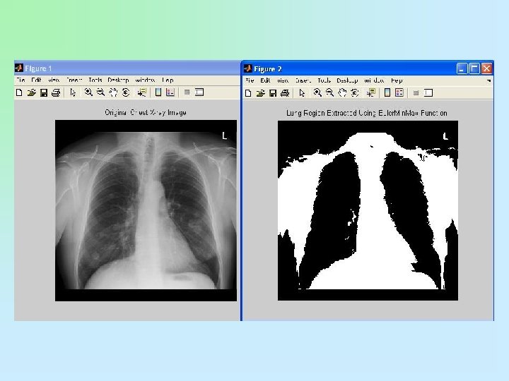
Image Display • spatial resolution contrast resolution/dynamic range
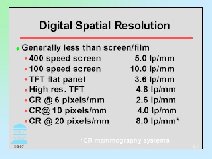
Spatial Resolution • Spatial resolution refers to the amount of detail present in any image. • Phosphor layer thickness and pixel size determines resolution in CR. • The thinner the phosphor layer is, the higher resolution. • Film/screen radiography resolution at its best is limited to 10 line pairs per millimeter (lp/mm). • CR resolution is 2. 55 lp/mm to 5 lp/mm, resulting in less detail.
Spatial Resolution • CR dynamic range, or the number of recorded densities, is much higher, and lack of detail is difficult to discern. • More tissue densities on the digital radiograph are seen, giving the appearance of more detail.
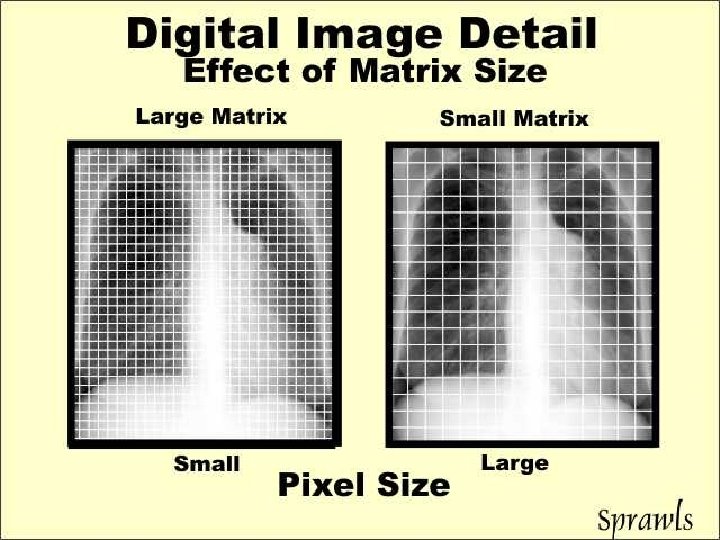
SPATIAL RESOLUTION
Spatial Resolution determined by: �� Pixel size. • CR- sampling frequency • DR – DEL size • �� There are relationships between • Pixel size • Receptor size • Matrix size • �� pixel size = larger matrix • �� receptor size = larger matrix • Spatial resolution is not related the amount of exposure
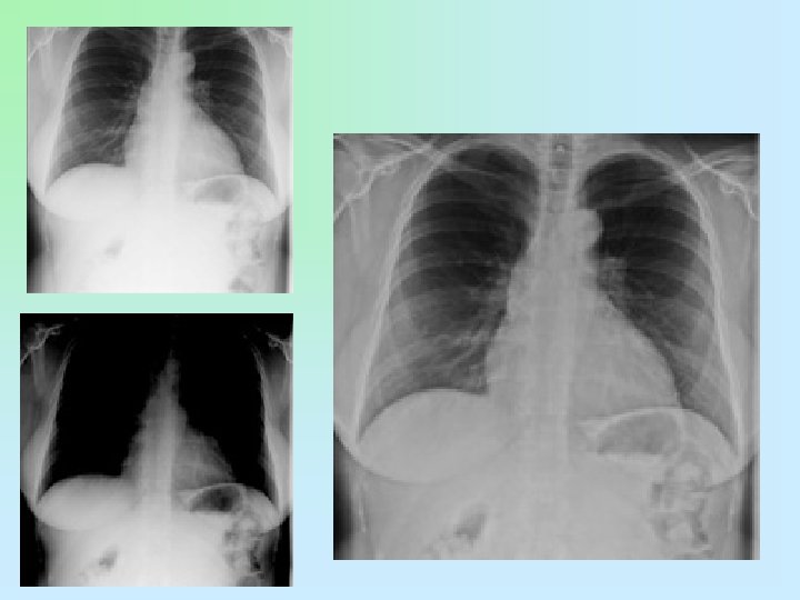
Spatial Resolution • knee radiograph typically does not show soft tissue structures. • A digital image shows not only the soft tissue but also the edge of the skin. This is due to the wider dynamic recording range and does not mean that there is additional detail.
Spatial Resolution • Depending on the physical characteristics of the detector, spatial resolution can vary a great deal. • Spatial resolution of amorphous selenium for direct detectors and cesium iodide for indirect detectors is higher than CR detectors but lower than film/screen radiography.
Spatial Resolution • Excessive image processing, in an effort to alter image sharpness, can lead to excessive noise. • Digital images can be processed to alter apparent image sharpness; however, excessive processing can lead to an increase in perceived noise. • The best resolution is achieved by using the appropriate technical factors and materials.
Speed • In conventional radiography, speed is determined by the size and layers of crystals in the film and screen. • In CR, speed is not exactly the same because there is no intensifying screen or film. • The phosphors emit light according to the width and intensity of the laser beam as it scans the plate, resulting in a relative speed that is roughly equivalent to a 200 -speed film/screen system.
Speed • CR system speeds are a reflection of the amount of photostimulable luminescence given off by the imaging plate while being scanned by the laser. • For example, Fuji Medical Systems reports that a 1 -m. R exposure at 80 k. Vp and a source-to-image distance of 72 inches will result in a luminescence value of 200, hence the speed number.
Speed • In CR, most cassettes have the same speed; however, there are special extremity or chest cassettes that produce greater resolution. • These are typically 100 relative speed. • Great care must be taken when converting to a CR system from a film/screen system to adjust technical factors to reflect the new speed.
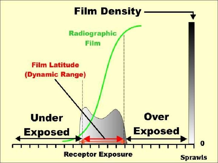
Exposure Latitude or Dynamic Range • Conventional radiography • Based on the characteristic response of the film, which is nonlinear. • Radiographic contrast is primarily controlled by kilovoltage peak. • Optical density on film is primarily controlled by milliampere-second setting.
CR Cassettes • Because so many more densities are recorded in CR (wide dynamic range), images appear more detailed. • Because energy stored in the imaging plate is lost over time, imaging plates should be read as quickly as possible to avoid image information loss. • Imaging plates are erased by exposing them to bright light such as fluorescent light.
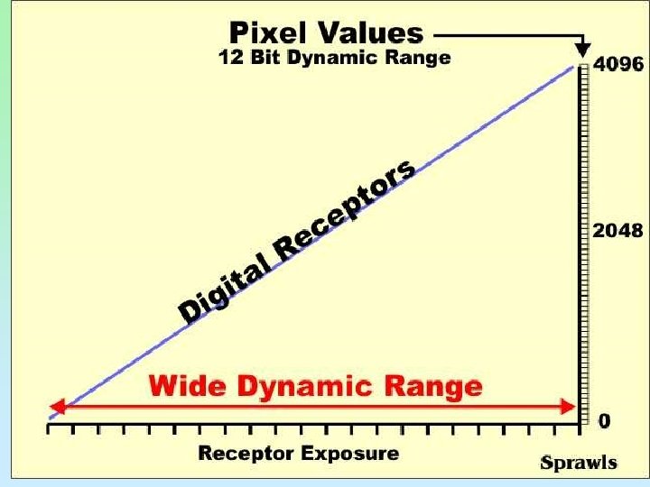
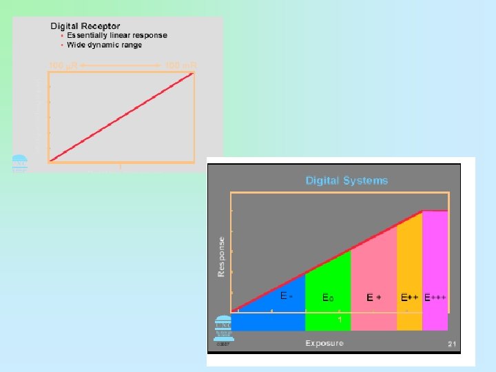
Exposure Latitude or Dynamic Range • CR and DR • Contain a detector that can respond in a linear manner. • Exposure latitude is wide, allowing the single detector to be sensitive to a wide range of exposures. • Kilovoltage peak still influences subject contrast, but radiographic contrast is primarily controlled by an image processing look-up table. LUT • Milliampere-second setting has more control over image noise, whereas density is controlled by imageprocessing algorithms.
Density • . 25 TO -2. 5 • The straight line of the H&D curve
Optical Density • A numerical value indicating the degree of blackening on the film. (average OD seen on a radiograph = 1. 2 Range is 0. 21 – 2. 5) # of photons coming through film = # of photons hitting film OD # OD= 1 2 3 1 = 0 100 1 = 1 101 1 = 2 102 1 = 3 103 1 1000
Why do digital systems have significantly greater latitude? • Linear response give the imaging plates greater latitude • Area receving little radiation can be enhanced by the computer • Higer densities can be separated and brought down to the visibile density ranges
Note It is important to note that just because a • digital imaging system has the capacity to • produce an image from gross underexposure • or gross overexposure it does not equate to • greater exposure latitude. • The reason the system is capable of producing an image when significant exposure errors occur is through a process called automatic rescaling.
• In a digital system, underexposure of • 50% or greater will result in a mottled • image. • �� In a digital system, overexposure • greater than 200% of the ideal will result • in loss of image contrast.
Look-Up Table • The look-up table (LUT) is a reference histogram. • LUT is used as a cross-reference to transform the raw information. • LUT is used to correct values. • LUT has a mapping function: • All pixels are changed to a new gray value. • Image will have appropriate appearance in brightness and contrast. • LUT is provided for every anatomic part.
Look-Up Table • LUT can be graphed as follows: • Plotting the original values ranging from 0 to 255 on the horizontal axis • Plotting new values, also ranging from 0 to 255 on the vertical axis • Contrast can be increased or decreased by changing the slope of this graph. • Brightness (density) can be increased or decreased by moving the line up or down the y-axis.
Histogram Analysis • It is important to choose the correct anatomic region on the menu before exposing the patient. • Raw data used to form the histogram are compared with a “normal” histogram of the same body part by the computer.
Image Receptors digital image characteristics – spatial resolution – sampling frequency – DEL (detector element size) – receptor size and matrix size – image signal (exposure related) – quantum mottle – SNR (signal to noise ratio) or – CNR (contrast to noise ratio)
Matrix size is determined by. . . • �� Receptor size (Field of View: FOV) • �� Pixel size • CR - Sampling frequency • DR - DEL size (Dector ELement)
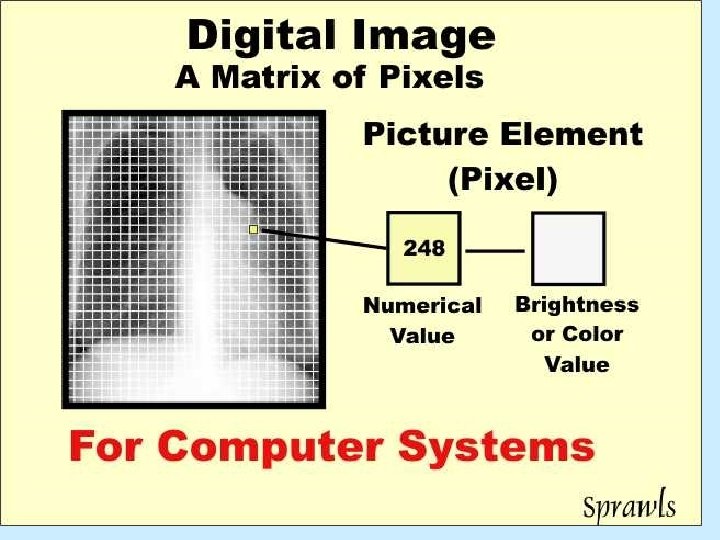
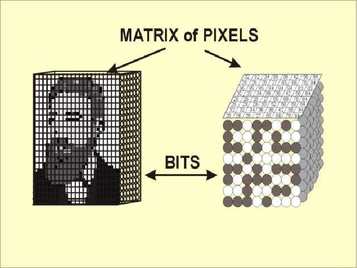
DIGITAL: MATRIX SIZE • The number of rows and columns of • pixels in the image representation. • 7 X 7
Digital - Grayscale Bit depth. �� Number of gray shades available for display • 8 bit 256 • 10 bit 1024 • 12 bit 4096 • 14 bit 16384
Digitizing the Signal • So, how bright a pixel is determines where it will be located in the matrix in conjunction with the amount of gray level or bit depth. • Some CR systems have bit depths of 10 or 12, resulting in more shades of gray. • Each pixel can have a gray level between 0 (20) and 4096 (212). The gray level will be a factor in
Summary • Pixel and matrix size are important in determining the amount of resolution and the size of the image to be stored in the PACS system. In TFT technology, pixel and matrix size are determined by the amount of area available to “fill” with photons.
ARRT SPECS - DIGITAL • PACS • HIS (hospital information system) - work list • RIS (radiology information system) • DICOM • Workflow (inappropriate documentation, lost images, mismatched images, corrupt data) • windowing and leveling
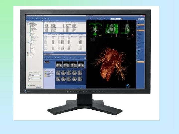
Picture Archival and Communication Systems • Networked group of computers, servers, and archives to store digital images • Can accept any image that is in DICOM format • Serves as the file room, reading room, duplicator, and courier • Provides image access to multiple users at the same time, ondemand images, electronic annotations of images, and specialty image processing
PACS
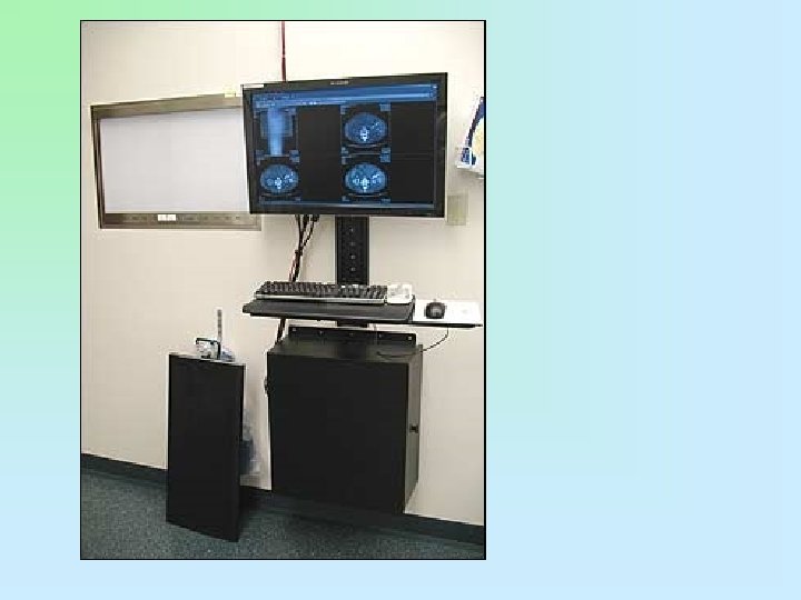
PACS Uses • Made up of different components • • Reading stations Physician review stations Web access Technologist quality control stations Administrative stations Archive systems Multiple interfaces to other hospital and radiology systems
DICOM • stands for digital imaging and communications in medicine, and it is a universally accepted standard for exchanging medical images between networked medical devices.
HIS RIS • The HIS holds the patient’s full medical information from hospital billing to the inpatient ordering system. • The RIS holds all radiology-specific patient data from the patient scheduling information to the radiologist’s dictated and transcribed report.
HIS – RIS INTERFACE
Image Acquisition and Readout • PSP (photo-stimulable phosphor) • flat panel detectors – (direct and indirect) • • • Noise Acceptable Range of Exposure Indicator Determination Gross Exposure Error Image Degradation (mottle, light or dark, low contrast)
Exposure Indicators • The amount of light given off by the imaging plate is a result of the radiation exposure that the plate has received. • The light is converted into a signal that is used to calculate the exposure indicator number, which is a different number from one vendor to another.
Exposure Indicators • The base exposure indicator number for all systems designates the middle of the detector operating range. • For Fuji, Phillips, and Konica systems, the exposure indicator is known as the S, or sensitivity, number. • The S number is the amount of luminescence emitted at 1 m. R at 80 k. Vp, and it has a value of 200.
Exposure Indicators • The higher the S number with these systems, the lower the exposure. • For example, an S number of 400 is half the exposure of an S number of 200, and an S number of 100 is twice the exposure of an S number of 200.
Exposure Indicators • The numbers have an inverse relationship to the amount of exposure so that each change of 200 results in a change in exposure by a factor of 2. • Kodak uses exposure index, or EI, as the exposure indicator. • A 1 m. R exposure at 80 k. Vp combined with aluminum/copper filtration yields an EI number of 2000.
Exposure Indicators • An EI number plus 300 (EI + 300) is equal to a doubling of exposure, and an EI number of minus 300 (EI − 300) is equal to a halving of exposure. • The numbers for the Kodak system have a direct relationship to the amount of exposure so that each change of 300 results in change in exposure by a factor of 2.
Exposure Indicators • This is based on logarithms, only instead of using 0. 3 (as is used in conventional radiographic characteristic curves) as a change by a factor of 2, the larger number 300 is used. • This is also a direct relationship; the higher the EI, the higher the exposure.
Exposure Indicators • The term for exposure indicator in an Agfa system is the lg. M, or logarithm of the median exposure. • An exposure of 20 µGy at 75 k. Vp with copper filtration yields an lg. M number of 2. 6. • Each step of 0. 3 above or below 2. 6 equals an exposure factor of 2. • An lg. M of 2. 9 equals twice the exposure of 2. 6 lg. M, and an lg. M of 2. 3 equals an exposure half that of 2. 6. • The relationship between exposure and lg. M is direct
Image Receptors digital image characteristics – spatial resolution – sampling frequency – DEL (detector element size) – receptor size and matrix size – image signal (exposure related) – quantum mottle – SNR (signal to noise ratio) or – CNR (contrast to noise ratio)
Stiching an image
Portrait vs landscape mode
Edge enhancement & post processing
Enhanced Visualization Image Processing • • • Kodak Takes image diagnostic quality to a new level Increases latitude while preserving contrast Process decreases windowing and leveling Virtually eliminates detail loss in dense tissues
Grid Selection • Digital images are displayed in tiny rows of picture elements or pixels. • Grid lines that are projected on the imaging plate when using a stationary grid can interfere with the image, resulting in a wavy artifact known as a moiré pattern. • This pattern occurs because the grid lines
Collimation • Although the use of a grid decreases the amount of scatter that exits the patient from affecting latent image formation, properly used collimation reduces the area of irradiation and reduces the volume of tissue in which scatter can be created.
Collimation • This results in increased contrast because of the reduction of scatter as fog and reduces the amount of grid cleanup necessary for increased resolution. • Through postexposure image manipulation known as shuttering, a black background can be added around the original collimation edges, virtually eliminating the distracting white or clear areas.
Collimation • However, this technique is not a replacement for proper preexposure collimation. • Shuttering is an image aesthetic only and does not change the amount or angles of scatter created. • There is no substitute for appropriate collimation, for collimation reduces patient dose.
Automatic Data Recognition • Collimation is automatically recognized, and a complete histogram analysis occurs. • Good collimation practices are critical because overcollimation or undercollimation leads to data recognition errors that affect the histogram.
Mis registration – needs reprocessing
Common CR Image Acquisition Errors • As with film screen, artifacts can detract and degrade images. – Imaging plate artifacts • • Plate reader artifacts Image processing artifacts Printer artifacts Operator errors
Imaging Plate Artifacts • As the imaging plate ages, it becomes prone to cracks from the action of removing and replacing the imaging plate within the reader. • Cracks in the imaging plate appear as areas of lucency on the image.
Imaging Plate Artifacts • Adhesive tape used to secure lead markers to the cassette can leave residue on the imaging plate. • If static exists because of low humidity, hair can cling to the imaging plate.
Imaging Plate Artifacts • Backscatter created by x-ray photons transmitted through the back of the cassette can cause dark line artifacts. • Areas of the lead coating of the cassette that are worn or cracked allow scatter to image these weak areas. Proper collimation and regular cassette inspection helps to eliminate this problem.
Plate Reader Artifacts • The intermittent appearance of extraneous line patterns can be caused by problems in the electronics of the plate reader. • Reader electronics may have to be replaced to remedy this problem.
Plate Reader Artifacts • Incorrect erasure settings result in a residual image left in the imaging plate before the next exposure. • Results vary depending on how much residual image is left and where it is located. • Orientation of a grid so that the grid lines are parallel to the laser scan lines of the plate reader results in the moiré pattern error. Grids should be high frequency, and the grid lines should run perpendicular to the laser scan lines of the plate reader.
Operator Errors • Insufficient collimation results in unattenuated radiation striking the imaging plate. • The resulting histogram is changed so that it is outside the normal exposure indicator range for the body part selected. • Using the smallest imaging plate possible and proper collimation, especially on small or thin patients, eliminates this error.
Operator Errors • If the cassette is exposed with the back of a cassette toward the source, the result is an image with a white grid-type pattern and white areas that correspond to the hinges. • Care should be taken to expose only the tube side of the cassette.