Digital Design Module 2 Multiplexer and Demultiplexer Amit


 A multiplexer can use addressing bits to select one of several input")

 1 MUX Inputs 2 N (destination) N Select Lines Output")

 Data inputs Control input Z = A′. I 0 +")

 D 1 D 2 MUX D 0 Y D 3")
 MSB A B F 0 0 I 0 0 1")
 MSB A B C F 0 0 0 I 0")


 = m( 1, 4,")

 A demultiplexer performs the opposite function of a multiplexer. • A DEMUX")

 N Select Lines 2 N Outputs (destinations)")

 DEMUX D 0 X B D 0 = A'. B'.")
- Slides: 27
Digital Design Module 2 Multiplexer and Demultiplexer Amit Kumar AP SCSE, GU Greater Noida
OUTLINE Introduction to Multiplexer • Implementation of 2 x 1, 4 x 1 and 8 x 1 Mux • Multiplexer with enable input • Cascading of Multiplexers • Combinational Logic Circuit Implementation using a Multiplexer • Introduction to De-multiplexer • Implementation of 1 x 4 De-Mux •
Multiplexer (MUX) A multiplexer can use addressing bits to select one of several input bits to be the output. n n A selector chooses a single data input and passes it to the MUX output It has one output selected at a time.
Cont. . A multiplexer has N control inputs 2 N data inputs 1 output A multiplexer routes (or connects) the selected data input to the output. The value of the control inputs determines the data input that is selected.
Block Diagram (sources) 1 MUX Inputs 2 N (destination) N Select Lines Output
Typical Application of a MUX Multiple Sources Selector Single Destination MP 3 Player Docking Station D 1 D 2 MUX D 0 Laptop Sound Card Y D 3 Surround System Digital Satellite Digital Cable TV B A Selected Source 0 0 MP 3 0 1 Laptop 1 0 Satellite 1 1 Cable TV
2 -to-1 Multiplexer (MUX) Data inputs Control input Z = A′. I 0 + A. I 1
2 x 1 mux
4 -to-1 Multiplexer (MUX) D 1 D 2 MUX D 0 Y D 3 B A Y 0 0 D 0 0 1 D 1 1 0 D 2 1 1 D 3
4 -to-1 Multiplexer (MUX) MSB A B F 0 0 I 0 0 1 I 1 1 0 I 2 1 1 I 3 LSB Z = A′. B'. I 0 + A'. B. I 1 + A. B'. I 2 + A. B. I 3
8 -to-1 Multiplexer (MUX) MSB A B C F 0 0 0 I 0 0 0 1 I 1 0 I 2 0 1 1 I 3 1 0 0 I 4 1 0 1 I 5 1 1 0 I 6 1 1 1 I 7 LSB Z = A′. B'. C'. I 0 + A'. B'. C. I 1 + A'. B. C'. I 2 + A'. B. C. I 3 + A. B'. C'. I 0 + A. B'. C. I 1 + A'. B. C'. I 2 + A. B. C. I 3
Function table with enable
Cascading multiplexers Using three 2 -1 MUX to make one 4 -1 MUX F S 1 S 0 F 0 0 I 0 0 1 I 1 1 0 I 2 1 1 I 3
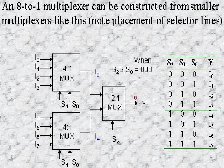
Example: Construct an 8 -to-1 multiplexer using 2 -to-1 multiplexers. S 2 S 1 S 0 F 0 0 0 I 0 0 0 1 I 1 0 I 2 0 1 1 I 3 1 0 0 I 4 1 0 1 I 5 1 1 0 I 6 1 1 1 I 7 I 0 I 1 I 2 I 3 F 2 -1 MUX I 4 I 5 I 6 I 7 S E S 2 E
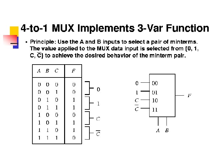
Implementing Boolean functions with multiplexers n n n Any Boolean function of n variables can be implemented with 2 n-1 -to-1 multiplexer. The procedure for implementing a Boolean function with a multiplexer is 1. Express the function in its sum of minterms form. 2. Order the sequence of variables chosen for the minterms. Suppose the sequence is , where A is the leftmost variable, and are the remaining n-1 variables.
CONT… n n 3. Connect the n-1 variables to the selection lines of the 2 n-1 -to-1 multiplexer, with B connected to the highest order selection line, and so on. 4. Construct the implementation table: List all the minterms in two rows. • • The first row consists of minterms 0 to 2 n-1 -1 (in all of which A is complemented). The second row consists of minterms 2 n-1 to 2 n-1 (in all of which A is uncomplemented). .
CONT. . n 5. Circle all the minterms of the function and inspect each column in the implementation table separately • • If the two minterms in a column are not circled, apply 0 to the corresponding multiplexer input. If the two minterms are circled, apply 1 to the corresponding multiplexer input. If the bottom minterm is circled, and the top is not circled, apply A to the corresponding multiplexer input. If the top minterm is circled but not the bottom, apply A*
Consider the function of 3 variables: 1. Input variables B and C are applied to the selection lines s 1 and s 0, respectively. 2. Construct the implementation table, and circle all the minterms of the function in the implementation table 3. Apply 0, 1, A, and inputs I 0 through I 3. to the
Implementing a Boolean Function using a Multiplexer G(x, y, z) = m( 1, 4, 5, 6 )
Multiplexer as a Full-Adder
De-Multiplexer (De-MUX) A demultiplexer performs the opposite function of a multiplexer. • A DEMUX is a digital switch with a single input (source) and a multiple outputs (destinations). • The select lines determine which output the input is connected to.
Cont. . A demultiplexer has N control inputs 1 data input 2 N outputs A demultiplexer routes (or connects) the data input to the selected output. The value of the control inputs determines the output that is selected.
Block Diagram- De-Mux DEMUX Input 1 (source) N Select Lines 2 N Outputs (destinations)
Typical Application of a DEMUX Selector Single Source Multiple Destinations B/W Laser Printer Fax Machine X DEMUX D 0 D 1 Color Inkjet Printer D 2 D 3 B A Selected Destination 0 0 B/W Laser Printer 0 1 Fax Machine 1 0 Color Inkjet Printer 1 1 Pen Plotter
1 -to-4 De-Multiplexer (DEMUX) DEMUX D 0 X B D 0 = A'. B'. X D 1 = A. B'. X D 2 = A'. B. X D 3 = A. B. X D 1 D 2 D 3 A B A D 0 D 1 D 2 D 3 0 0 X 0 0 1 0 0 0 X 0 1 1 0 0 0 X