
Digital Circuit Design Jeffrey N Denenberg Lecture 1
Digital Circuit Design Jeffrey N. Denenberg Lecture #1 Introduction, Logic Circuits J. N. Denenberg Lecture 1: Intro and Logic Circuits
Administrative • Handouts – Course Syllabus (readings due before lecture) http: //Doctor. D. Web. Hop. net – Linked Resources on Syllabus • Grading – 20% Homework (Due the week following the lecture on that topic) – 2 midterms (40%) + cumulative final (40%) – all exams required; make arrangements in advance if you have a conflict. – Lab Note: You should prepare prior to Lab session • Paper design (if required) • Functioning simulation J. N. Denenberg Lecture 1: Intro and Logic Circuits 2
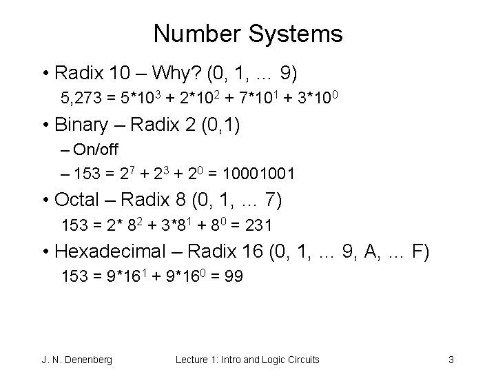
Number Systems • Radix 10 – Why? (0, 1, … 9) 5, 273 = 5*103 + 2*102 + 7*101 + 3*100 • Binary – Radix 2 (0, 1) – On/off – 153 = 27 + 23 + 20 = 10001001 • Octal – Radix 8 (0, 1, … 7) 153 = 2* 82 + 3*81 + 80 = 231 • Hexadecimal – Radix 16 (0, 1, … 9, A, … F) 153 = 9*161 + 9*160 = 99 J. N. Denenberg Lecture 1: Intro and Logic Circuits 3
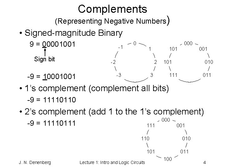
Complements (Representing Negative Numbers) • Signed-magnitude Binary 9 = 00001001 Sign bit -9 = 10001001 -1 0 000 1 -2 101 2 -3 001 101 3 010 111 011 • 1’s complement (complement all bits) -9 = 11110110 • 2’s complement (add 1 to the 1’s complement) 000 -9 = 11110111 001 110 010 101 J. N. Denenberg Lecture 1: Intro and Logic Circuits 011 100 4

Illustrative Example: 9’s Complement • Decimal Subtraction 575 - 57 518 • 9’s Complement -057 = 942 575 1517 now “wrap” the “overflow” around add for the answer 518 • 10’s Complement -057 = 942+1 = 943 575 1518 Here ignore the “overflow” to get 518 J. N. Denenberg Lecture 1: Intro and Logic Circuits 5
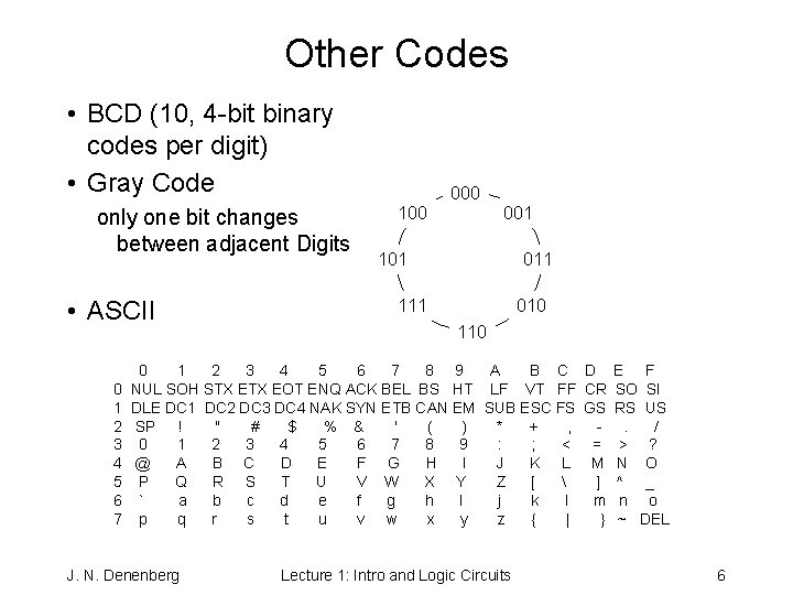
Other Codes • BCD (10, 4 -bit binary codes per digit) • Gray Code only one bit changes between adjacent Digits • ASCII 0 1 2 3 4 5 6 7 000 100 001 101 011 111 010 110 0 1 2 3 4 5 6 7 8 9 A B C NUL SOH STX EOT ENQ ACK BEL BS HT LF VT FF DLE DC 1 DC 2 DC 3 DC 4 NAK SYN ETB CAN EM SUB ESC FS SP ! " # $ % & ' ( ) * + , 0 1 2 3 4 5 6 7 8 9 : ; < @ A B C D E F G H I J K L P Q R S T U V W X Y Z [ ` a b c d e f g h I j k l p q r s t u v w x y z { | J. N. Denenberg Lecture 1: Intro and Logic Circuits D CR GS = M ] m } E F SO SI RS US. / > ? N O ^ _ n o ~ DEL 6
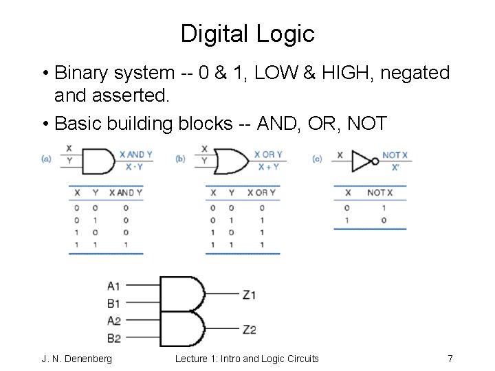
Digital Logic • Binary system -- 0 & 1, LOW & HIGH, negated and asserted. • Basic building blocks -- AND, OR, NOT J. N. Denenberg Lecture 1: Intro and Logic Circuits 7
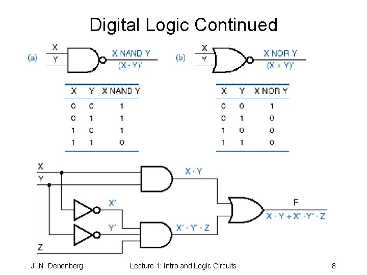
Digital Logic Continued J. N. Denenberg Lecture 1: Intro and Logic Circuits 8

Many representations of digital logic • Transistor-level circuit diagrams • Gate symbols (for simple elements) J. N. Denenberg Lecture 1: Intro and Logic Circuits 9

• Truth tables • Logic diagrams J. N. Denenberg Lecture 1: Intro and Logic Circuits 10
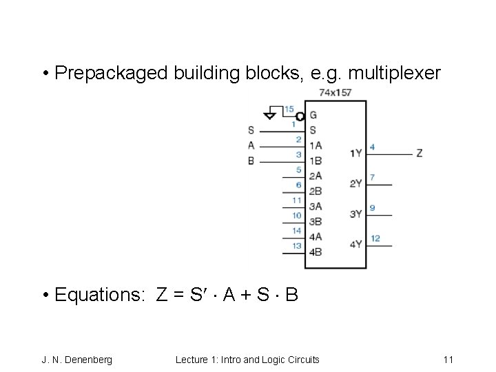
• Prepackaged building blocks, e. g. multiplexer • Equations: Z = S¢ × A + S × B J. N. Denenberg Lecture 1: Intro and Logic Circuits 11
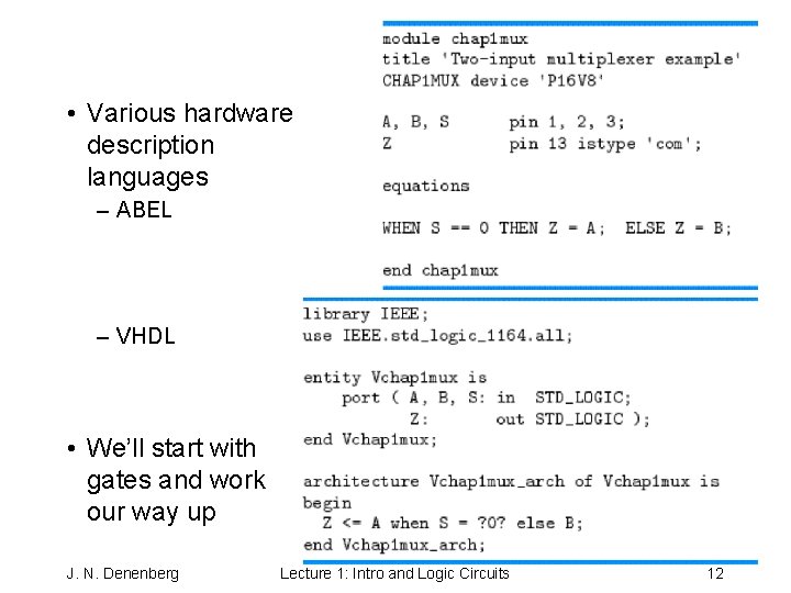
• Various hardware description languages – ABEL – VHDL • We’ll start with gates and work our way up J. N. Denenberg Lecture 1: Intro and Logic Circuits 12
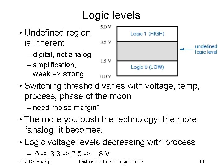
Logic levels • Undefined region is inherent – digital, not analog – amplification, weak => strong • Switching threshold varies with voltage, temp, process, phase of the moon – need “noise margin” • The more you push the technology, the more “analog” it becomes. • Logic voltage levels decreasing with process – 5 -> 3. 3 -> 2. 5 -> 1. 8 V J. N. Denenberg Lecture 1: Intro and Logic Circuits 13
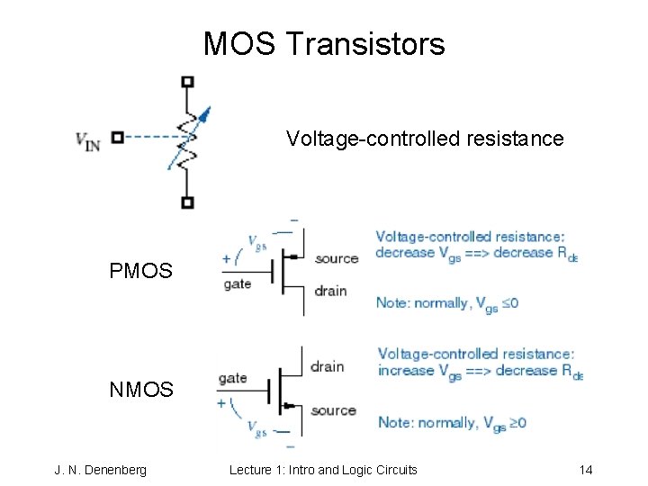
MOS Transistors Voltage-controlled resistance PMOS NMOS J. N. Denenberg Lecture 1: Intro and Logic Circuits 14
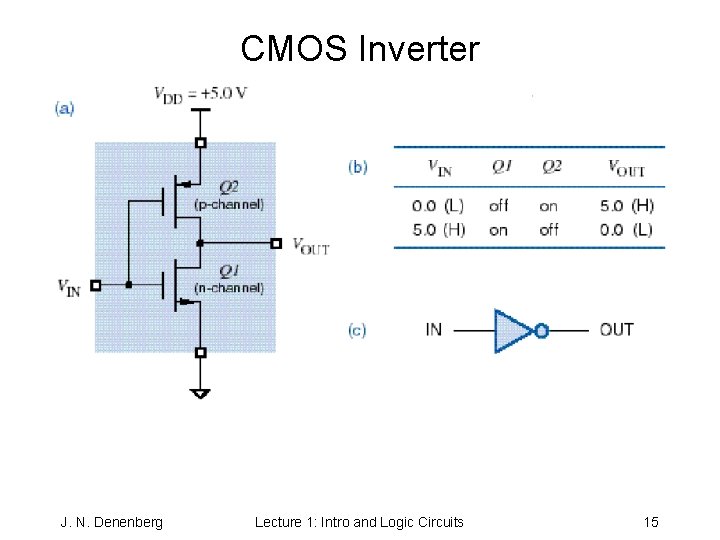
CMOS Inverter J. N. Denenberg Lecture 1: Intro and Logic Circuits 15
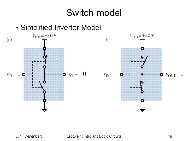
Switch model • Simplified Inverter Model J. N. Denenberg Lecture 1: Intro and Logic Circuits 16
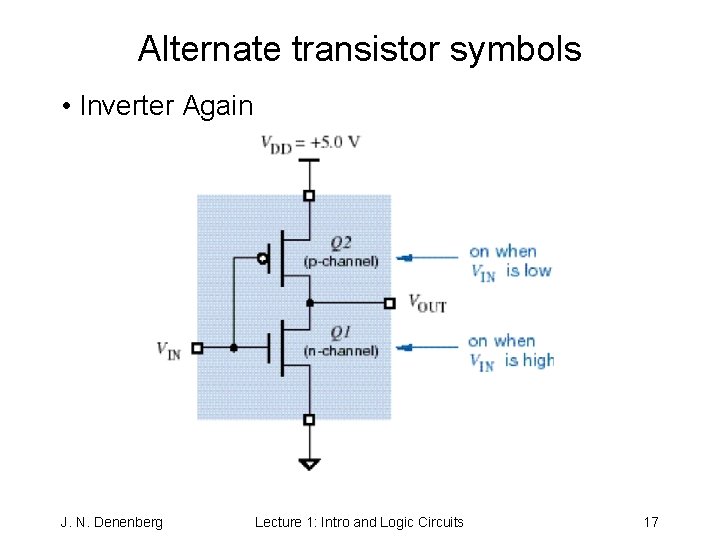
Alternate transistor symbols • Inverter Again J. N. Denenberg Lecture 1: Intro and Logic Circuits 17
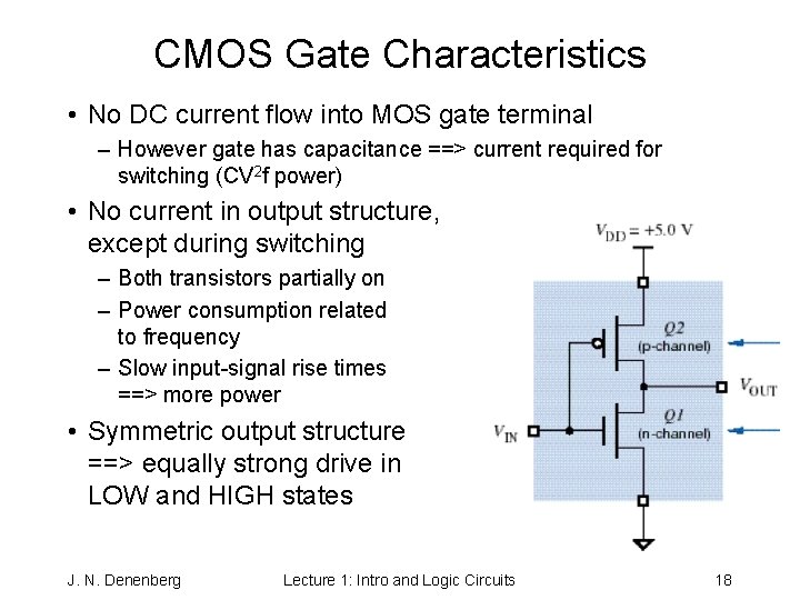
CMOS Gate Characteristics • No DC current flow into MOS gate terminal – However gate has capacitance ==> current required for switching (CV 2 f power) • No current in output structure, except during switching – Both transistors partially on – Power consumption related to frequency – Slow input-signal rise times ==> more power • Symmetric output structure ==> equally strong drive in LOW and HIGH states J. N. Denenberg Lecture 1: Intro and Logic Circuits 18
- Slides: 18