
Digital Audio Processor William Buttinger and Dimitri Podoliev
Digital Audio Processor William Buttinger and Dimitri Podoliev
Project Overview l Highly customizable digital audio system l Provide pre-built effects packages with user-specifiable parameters l Use audio “building blocks” with the packages to create unique effects l Use a computer to configure the processor
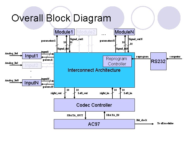
Overall Block Diagram Module 1 Module 2 parameters 1 Signal_out 1 18 18 Module. N … Signal_in 1 Analog_In 2 Analog_In. N Input 1 Input 2. . Input. N Signal_out. N parameters. N 18 18 Signal_in. N input 1 Reprogram Controller params 1 reprogram computer RS 232 Interconnect Architecture input. N params. N 18 right_out 18 Left_out 18 right_in 18 Left_in Codec Controller SDATA_IN SDATA_OUT AC 97 Bit_clock To all modules
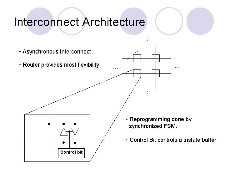
Interconnect Architecture … • Asynchronous Interconnect • Router provides most flexibility … … … • Reprogramming done by synchronized FSM. • Control Bit controls a tristate buffer Control bit
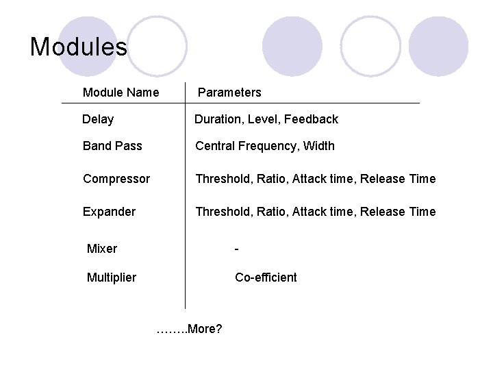
Modules Module Name Parameters Delay Duration, Level, Feedback Band Pass Central Frequency, Width Compressor Threshold, Ratio, Attack time, Release Time Expander Threshold, Ratio, Attack time, Release Time Mixer - Multiplier Co-efficient ……. . More?
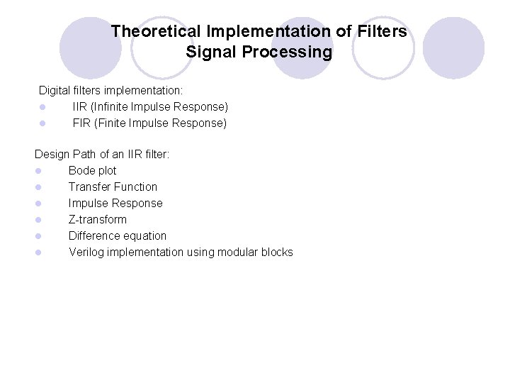
Theoretical Implementation of Filters Signal Processing Digital filters implementation: l IIR (Infinite Impulse Response) l FIR (Finite Impulse Response) Design Path of an IIR filter: l Bode plot l Transfer Function l Impulse Response l Z-transform l Difference equation l Verilog implementation using modular blocks
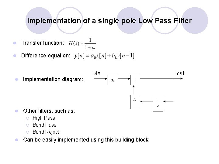
Implementation of a single pole Low Pass Filter l Transfer function: l Difference equation: l Implementation diagram: l Other filters, such as: ¡ ¡ ¡ l High Pass Band Reject Can be easily implemented using this building block
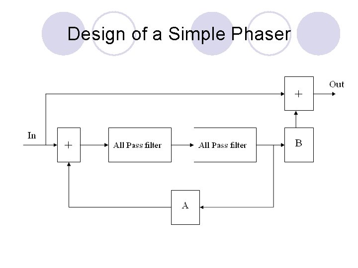
Design of a Simple Phaser
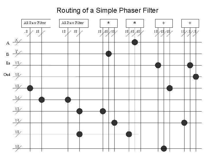
Routing of a Simple Phaser Filter
Questions?
- Slides: 10