Dielectrics Conductor has free electrons Dielectric electrons are


 Exy 1=Exy 2")


 Q =")


 and its")


- Slides: 28
Dielectrics • Conductor has free electrons. • Dielectric electrons are strongly bounded to the atom. • In a dielectric, an externally applied electric field, Eext cannot cause mass migration of charges since none are able to move freely. • But, Eext can polarize the atoms or molecules in the material. • The polarization is represented by an electric dipole.
• Note the field will apply a force on both the positively charged nucleus and the negatively charged electron. However, these forces will move these particles in opposite directions • Note, an electric dipole has been created !
D, flux density is proportionally increase as polarization increase through induction of permittivity, ε of the material relating the E and D permittivity, ε = proportional to the permittivity of free space, ε 0 ε = εr ε 0
• However, the electron may be break free from the atom, creating a positive ion and a free electron. • We call these free charges, and the electric field will cause them to move in opposite directions : • Moving charge is electric current J(r ).
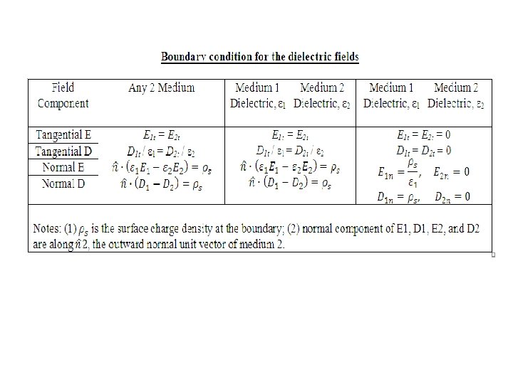
Electric Boundary Conditions • Electric field maybe continuous in each of two dissimilar media Dielectric and • But, the E-field maybe discontinuous at the dielectric boundary between them • Boundary conditions specify how the tangential Boundary Dielectric and normal components of the field in one conductor condition medium are related to the components in other medium across the boundary Conductor and • Two dissimilar media could be: two different conductor dielectrics, or a conductor and a dielectric, or two conductors
Dielectric- dielectric boundary • Interface between two dielectric media
Dielectric- dielectric boundary • Based on the figure in previous slide: • First boundary condition related to the tangential components of the electric field E is: • Second boundary condition related to the normal components of the electric field E is: • OR
z ε 1 E 2 Exy 1 ε 2 Ez 1 Exy 2 Ez 2 xy -plane
xy • Solution: ε 1=2ε 0 ε 2=5ε 0 1) Exy 1=Exy 2 thus, Exy 2 = 3 ax+4 ay 2) Ez 1 = 5 az, but, Ez 2 = ? ? E 2 Ө 1 z E 1 Example 1: 1) Find E 2 in the dielectric, when E 1 = 3 ax+4 ay+5 az, 2) And find Ө 1 and Ө 2. 2ε 0(5 az) = 5ε 0(Ez 2) Ez 2 = 2 az thus, E 2 =3 az+4 ay+2 az
z ε 1=2ε 0 Ө 2 ε 2=8ε 0 E 1 E 2 xy Ө 1 Find E 1 if E 2 = 2 x -3 y +3 z with s = 3. 54 x 10 -11(C/m 2) And find Ө 1 and Ө 2
Conductor- conductor boundary • Boundary between two conducting media: • Using the 1 st and 2 nd boundary conditions: and
xy J 2 Jz 1 Jxy 1 Jz 2 J 1 Jxy 2 z
Conductor- conductor boundary • In conducting media, electric fields give rise to current densities. • From , we have: and • The normal component of J has be continuous across the boundary between two different media under electrostatic conditions.
Conductor- conductor boundary • Hence, upon setting , we found the boundary condition for conductor- conductor boundary:
Dielectric-conductor boundary • Assume medium 1 is a dielectric • Medium 2 is a perfect conductor
Perfect conductor • When a conducting slab is placed in an external electric field, • Charges that accumulate on the conductor surfaces induces an internal electric field • Hence, total field inside conductor is zero.
Dielectric-conductor boundary • The fields in the dielectric medium, at the boundary with the conductor is . • Since , it follows that . • Using the equation, , • we get: • Hence, boundary condition at conductor surface: where = normal vector pointing outward
Dielectric-conductor boundary • Based on the figure in previous slide: • In a perfect conductor, • Hence, • This requires the tangential and normal components of E 2 and D 2 to be zero.
Capacitance • Capacitor – two conducting bodies separated by a dielectric medium ρs = Q / A ε 1 E ρs = surface charge density Q = charge (+ve / -ve) A = surface Area E E E = ρs/ε ε 2 E=0/V=0 on the surface
Capacitance • Capacitance is defined as: where: V = potential difference (V) Q = charge (C) C = capacitance (F)
Example 7 Obtain an expression for the capacitance C of a parallel-plate capacitor comprised of two parallel plates each of surface area A and separated by a distance d. The capacitor is filled with a dielectric material with permittivity ε.
Solution to Example 7 • expression for the capacitance C = Q/V ρs = Q / A and • the voltage difference is • Hence, the capacitance is:
Example 8 Use image theory to determine E at an arbitrary point P (x, y, z) in the region z > 0 due to a charge Q in free space at a distance d above a grounded conducting plane.
Solution to Example 8 • Charge Q is at (0, 0, d) and its image −Q is at (0, 0, −d) in Cartesian coordinates. Using Coulomb’s law, E at point P(x, y, z) due to two point charges:
Electrostatic potential energy • Assume a capacitor with plates of good conductors – zero resistance, • Dielectric between two conductors has negligible conductivity, σ ≈ 0 – no current can flow through dielectric • No ohmic losses occur anywhere in capacitor • When a source is connected to a capacitor, energy is stored in capacitor • Charging-up energy is stored in the form of electrostatic potential energy in the dielectric medium
Electrostatic potential energy • Electrostatic potential energy, • The capacitance: • Hence, We for a parallel plate capacitor:
Image Method • Image theory states that a charge Q above a grounded perfectly conducting plane is equal to Q and its image –Q with ground plane removed.