
Diamond like carbon Muresan Mihai Carbon Carbon is
Diamond like carbon Muresan Mihai
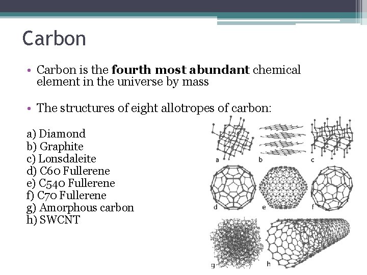
Carbon • Carbon is the fourth most abundant chemical element in the universe by mass • The structures of eight allotropes of carbon: a) Diamond b) Graphite c) Lonsdaleite d) C 60 Fullerene e) C 540 Fullerene f) C 70 Fullerene g) Amorphous carbon h) SWCNT
Carbon • Diamond – the hardest naturally occurring substance • Graphite – the cheapest fuel (coal), electrical conductor, heat resistant material and lubricant • Fullerenes – potential medical use • CNT – strongest and stiffest material, possible high electric conductivity, composite polymers, ultracapacitors • Graphene – ballistic electrical conductivity, gas detectors, IC, biodevices • a-C – a material that is not diamond or graphite
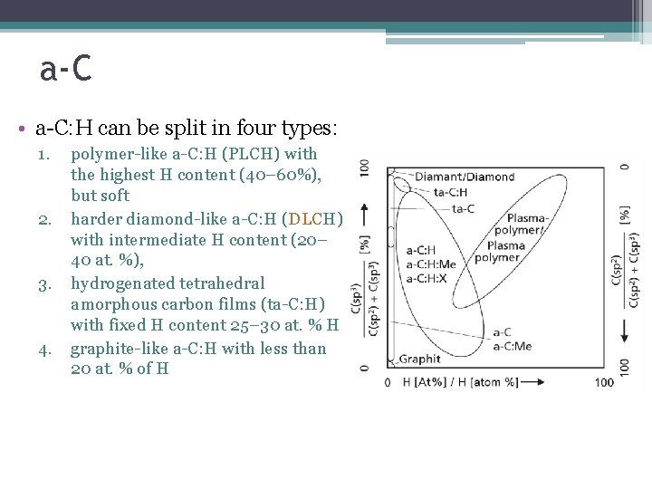
a-C • a-C: H can be split in four types: 1. 2. 3. 4. polymer-like a-C: H (PLCH) with the highest H content (40– 60%), but soft harder diamond-like a-C: H (DLCH) with intermediate H content (20– 40 at. %), hydrogenated tetrahedral amorphous carbon films (ta-C: H) with fixed H content 25– 30 at. % H graphite-like a-C: H with less than 20 at. % of H
a-C: H properties ØHigh thermal conductivity ØHigh hardness ØGood abrasion coefficient ØLow friction coefficient ØGas barrier ØInertness ØWide band gaps
a-C problems • Bad adhesion (especially on metals) • High stressed films • Thermal stability under 300 OC (a-C: H) • Solving the problems: ØFabrication of intermediate metallic layer ØIntermediate compound layer (WC, Ti. C) ØDoping with different elements

DLC uses
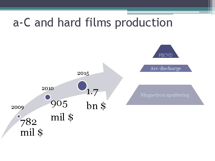
a-C and hard films production PECVD 2015 2010 2009 905 782 mil $ 1. 7 bn $ Arc discharge Magnetron sputtering
Why PECVD? • • • Relatively easy to produce plasma Pure deposition due to low pressure Large size depositions Precision of the coating Low melting point substrates Good dielectric properties
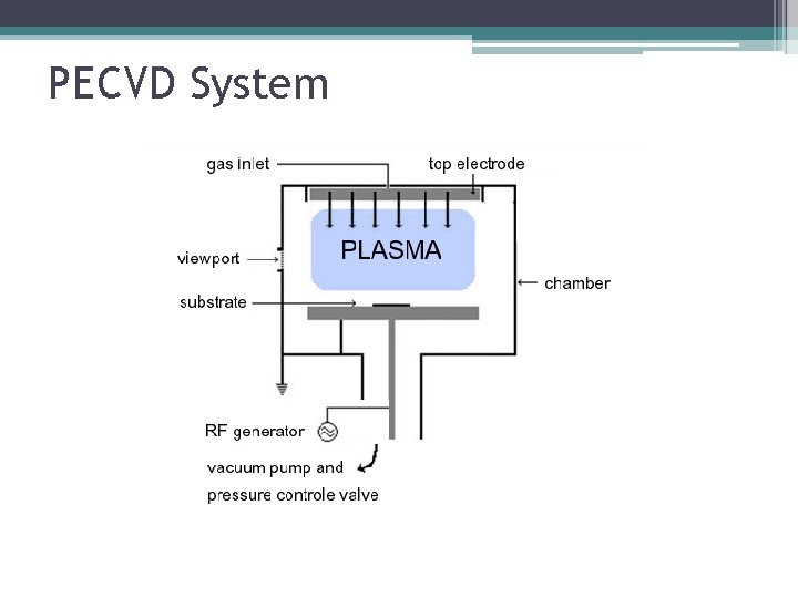
PECVD System
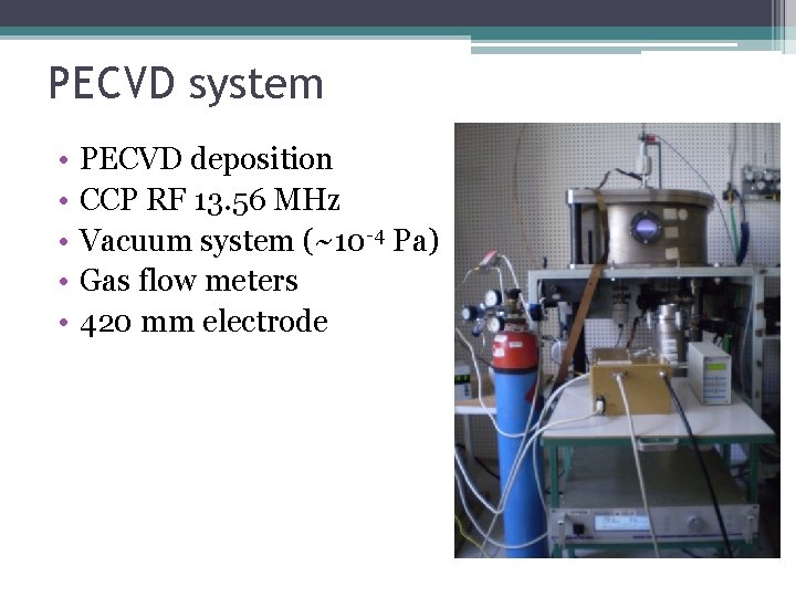
PECVD system • • • PECVD deposition CCP RF 13. 56 MHz Vacuum system (~10 -4 Pa) Gas flow meters 420 mm electrode
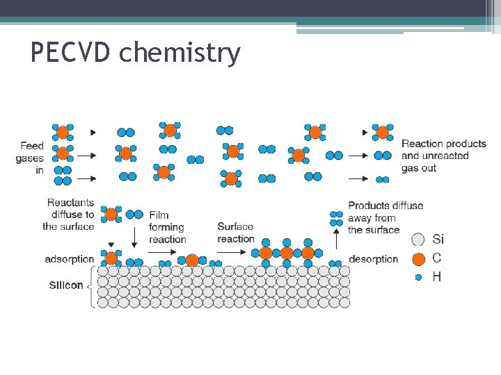
PECVD chemistry
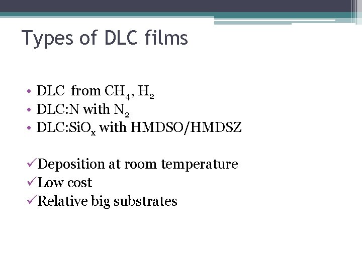
Types of DLC films • DLC from CH 4, H 2 • DLC: N with N 2 • DLC: Si. Ox with HMDSO/HMDSZ üDeposition at room temperature üLow cost üRelative big substrates
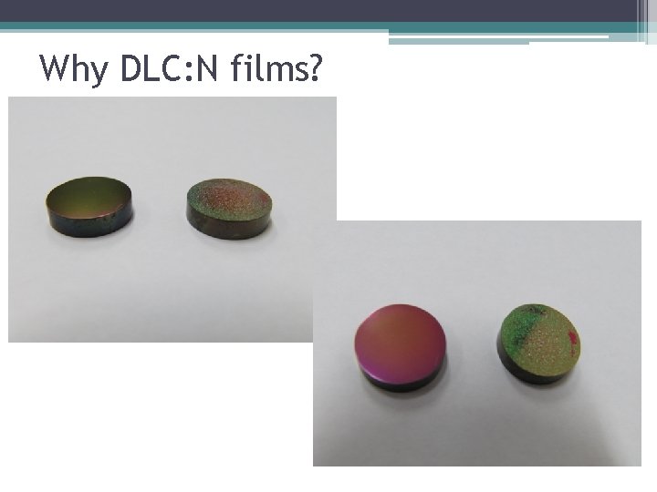
Why DLC: N films?
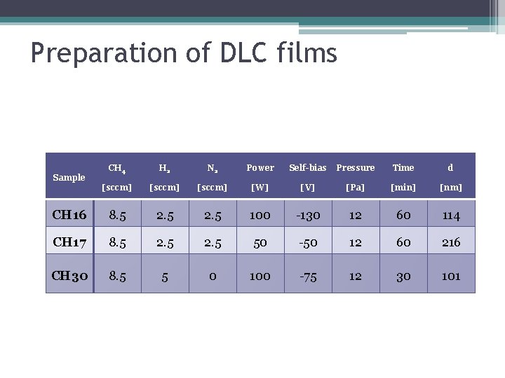
Preparation of DLC films CH 4 H 2 N 2 Power Self-bias Pressure Time d [sccm] [W] [V] [Pa] [min] [nm] CH 16 8. 5 2. 5 100 -130 12 60 114 CH 17 8. 5 2. 5 50 -50 12 60 216 CH 30 8. 5 5 0 100 -75 12 30 101 Sample
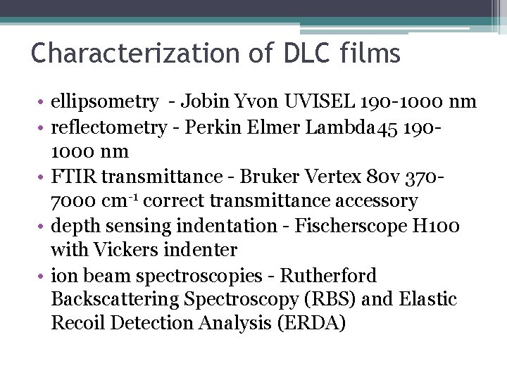
Characterization of DLC films • ellipsometry - Jobin Yvon UVISEL 190 -1000 nm • reflectometry - Perkin Elmer Lambda 45 1901000 nm • FTIR transmittance - Bruker Vertex 80 v 3707000 cm-1 correct transmittance accessory • depth sensing indentation - Fischerscope H 100 with Vickers indenter • ion beam spectroscopies - Rutherford Backscattering Spectroscopy (RBS) and Elastic Recoil Detection Analysis (ERDA)
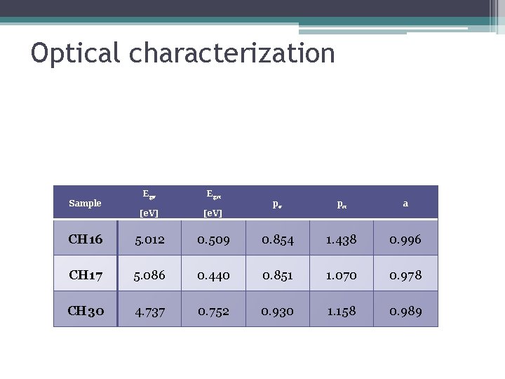
Optical characterization Egσ Egπ [e. V] CH 16 5. 012 CH 17 CH 30 Sample pσ pπ a 0. 509 0. 854 1. 438 0. 996 5. 086 0. 440 0. 851 1. 070 0. 978 4. 737 0. 752 0. 930 1. 158 0. 989
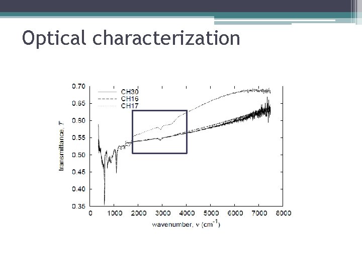
Optical characterization
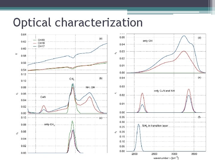
Optical characterization
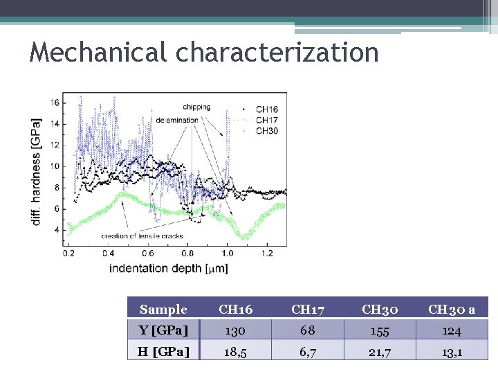
Mechanical characterization Sample CH 16 CH 17 CH 30 a Y [GPa] 130 68 155 124 H [GPa] 18, 5 6, 7 21, 7 13, 1
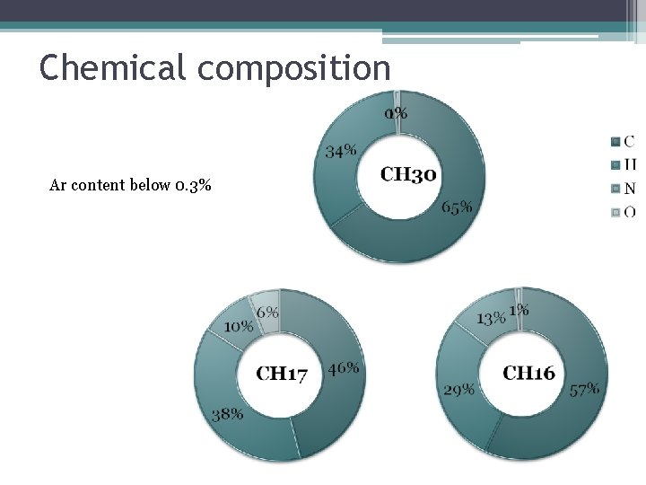
Chemical composition Ar content below 0. 3%
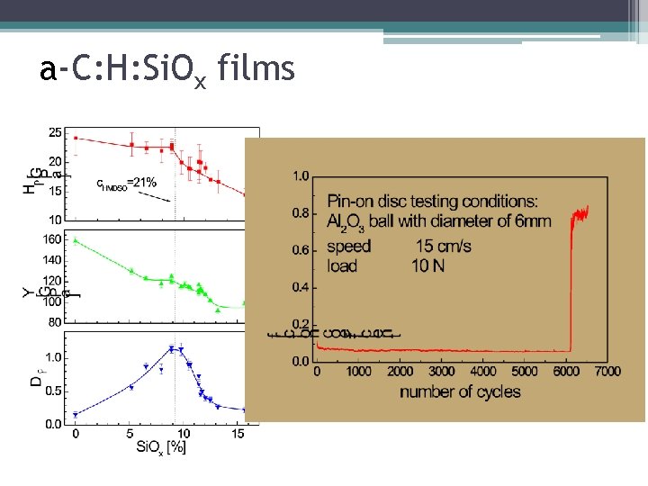
a-C: H: Si. Ox films
Conclusions üHard DLC films can be produced on low melting point substrates üDLC: N films can be used on metallic substrates üDLC: Si. Ox films present higher thermal stability o The method is relatively cheap, can cover large substrates and can be employed for low melting point substrates (plastics)

Thank you for your attention
- Slides: 24