Diagnostics equipment U Capacitor divider Differential divider Oscillograms


:")


 grounded electrode (anode) U=- 100 -150 k.")


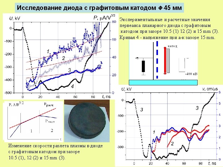
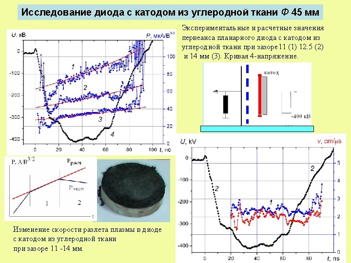
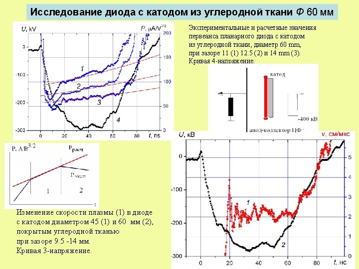
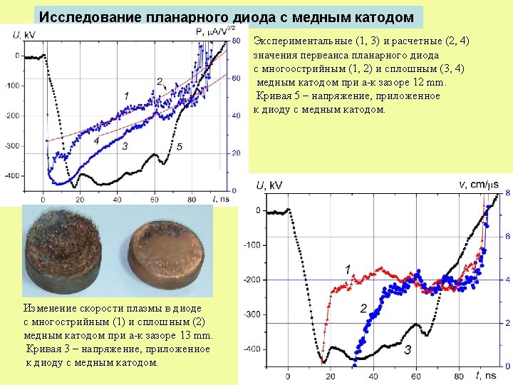
 and calculation (2) values of diode perveance during electron current pulse")


- Slides: 36
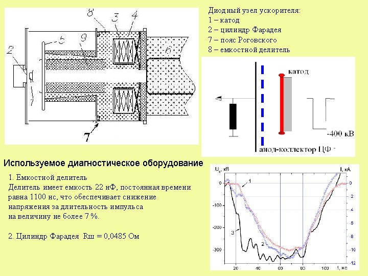
Diagnostics equipment U Capacitor divider Differential divider Oscillograms of voltage: 1 - capacitor divider 2 – differential divider (after integration) I Faraday cup, R = 0, 0485 Оhm Rogovsky coil Oscillograms of current: 1 - Faraday cup 3 - Rogovsky coil 4 4
Calculation of impedance from oscillograms of voltage and current Equivalent circuit of diode unit of pulsed electron accelerator R = 43. 5 Ohm. 5 5
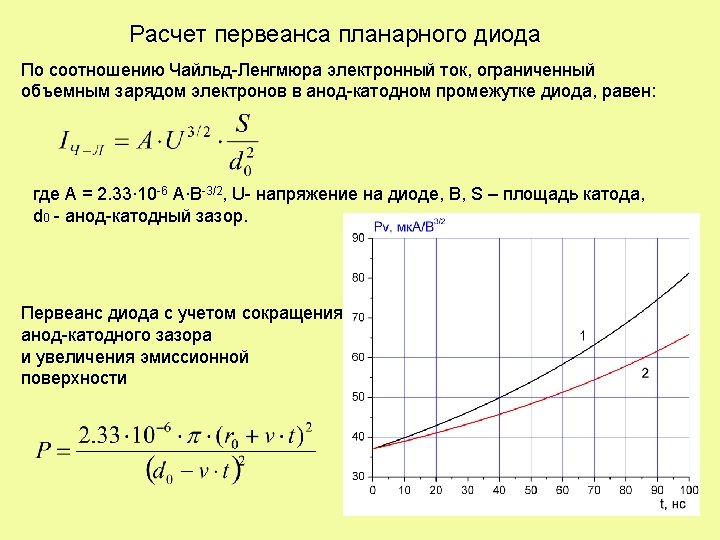
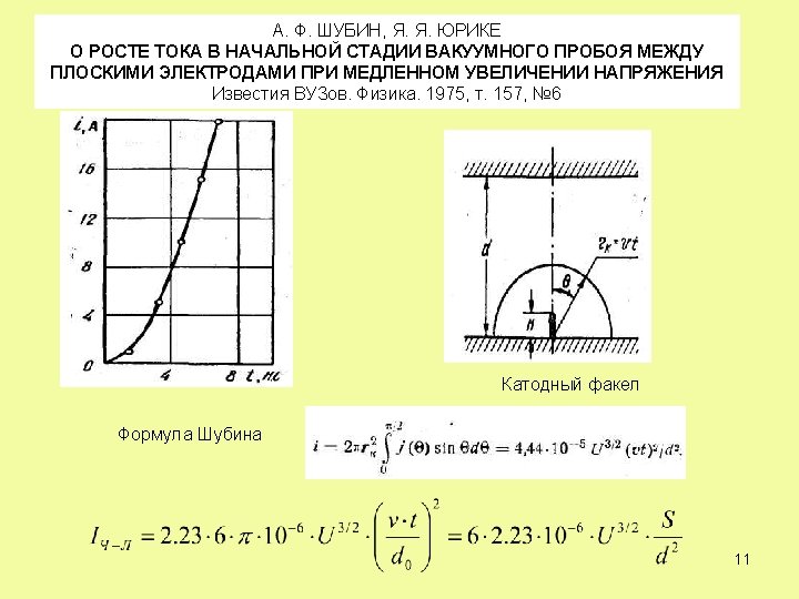
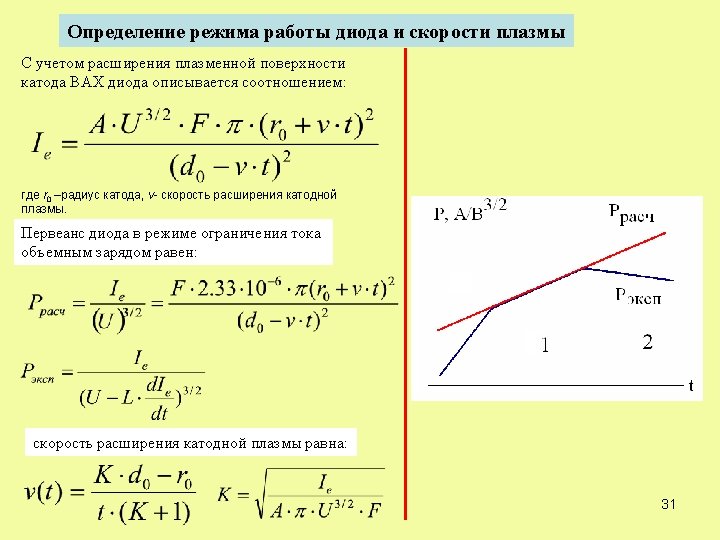
Calculation of diode perveance 1. Current density limited by space charge is (Child-Langmuir law): where ε 0 is absolute dielectric penetrability, e and m are charge and mass of electron, U is voltage, d is gap. 2. For the diode with explosive emission cathode where r 0 is initial radius of the cathode, v 1, v 2 are speeds of cathode plasma expansion to anode and crosswise to anode-cathode gap, 6 F – form-factor determined by the diode construction.
8
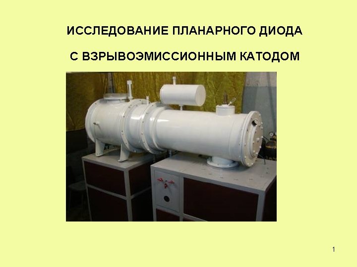
A Planar Diode Operating in the Mode of Limited Electron Emission A. I. Pushkarev, R. V. Sazonov, A. Ju. Patronov High Voltage Research Institute of Tomsk Polytechnic University, Tomsk, Russia, aipush@mail. ru 9
DISCRETE EMISSIVE SURFACE MODE potential electrode (cathode) grounded electrode (anode) U=- 100 -150 k. V Discrete explosion-emissive center 10
CIRCUIT MODELING of a VACUUM GAP DURING BREAKDOWN Goran Djogo and J. D. Cross //IEEE TRANSACTIONS ON PLASMA SCIENCE, VOL. 25, № 4, 1997. Table 1 Fitting coefficients for perveance formula gap a b с plane - plane 8. 09 7. 94 0 needle(-) - plane(+) -2. 9 15. 2 2. 7 3 cone(-) - plane(+) -10. 8 23. 5 2. 2 cone(+) - plane(-) -1. 68 3. 68 0 12
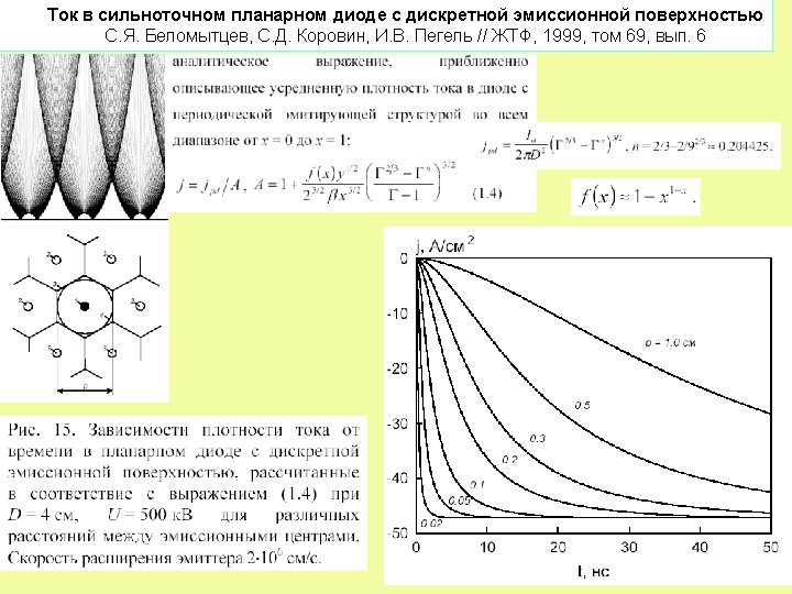
Pushkarev A. I. and Sazonov R. V. A Planar Diode Operating in the Regime of Limited Electron Emission // Technical Physics Letters, 2008, Vol. 34, No. 4, pp. 292– 295. Let us assume that • the emitting centers are equidistant from each other and form a uniform cellular structure on the cathode surface; • the emitting centers are formed simultaneously • their number remains the same during the entire period of the electron beam generation. where N - total number of emitting centers, α = 2 arcos(b/v·t), (in radians), b is the distance between the adjacent emitting centers 14
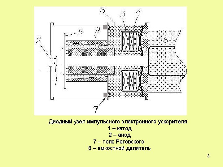
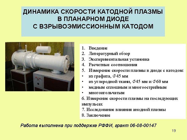
Experimental setup Diode unit of pulsed electron accelerator: 1 – cathode; 2 – anode; accelerating voltage 350 -450 k. V, full pulse duration 100 ns, total electron energy in pulse up to 250 J The block diagram of diode unit 15 15
16
The experimental (1) and calculation (2) values of diode perveance during electron current pulse generation for graphite cathode 60 mm in diameter when the gap is 12 (1), 13. 5 (2) and 15 mm (3). 17
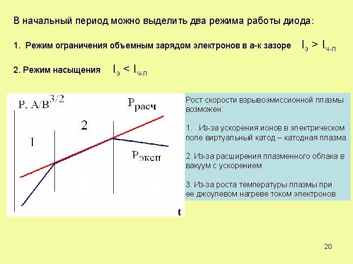
Conclusion The performed studies showed that the experimental characteristic of planar diode with graphite cathode in the initial period of time (with the discrete emission surface of cathode) is well described by the modified Child-Langmuir correlation under the condition of simultaneous appearance of separate emitters and increase of their radius at a constant speed. In the initial period of time when the emitter radius is much smaller than the distance between neighbor emitters the form-factor value in the modified Child-Langmuir correlation corresponds to the experimental values obtained while studying a single emission center. With the increase of emitter size the form-factor value reduces to 1. This corresponds to the volt-ampere characteristics of planar diode with solid emission surface at the cathode. 18
R. K. Parker, Richard E. Anderson, and Charles V. Duncan PLASMA-INDUCED FIELD EMISSION AND THE CHARACTERISTICS OF HIGH-CURRENT RELATIVISTIC ELECTRON FLOW // Journal of Applied Physics, Vol. 45, No. 6, June 1974. катод анод Первеанс диода равен: P = P 0 + P 1, Где Р 0 – первеанс плоской части катода, P 1 – первеанс периферийной области диода d is the effective diode separation, set equal to d 0 — vt. 24
CIRCUIT MODELING of a VACUUM GAP DURING BREAKDOWN Goran Djogo and J. D. Cross //IEEE TRANSACTIONS ON PLASMA SCIENCE, VOL. 25, № 4, 1997. Table 1 Fitting coefficients for perveance formula gap a b с plane - plane 8. 09 7. 94 0 needle(-) - plane(+) -2. 9 15. 2 2. 7 3 cone(-) - plane(+) -10. 8 23. 5 2. 2 cone(+) - plane(-) -1. 68 3. 68 0 27